当前位置:网站首页>Flight control implementation of four rotor aircraft "suggestions collection"
Flight control implementation of four rotor aircraft "suggestions collection"
2022-07-25 23:05:00 【Full stack programmer webmaster】
Hello everyone , I meet you again , I'm your friend, Quan Jun .
Try to make this four rotor flight control process , Many feelings , After sorting out my thoughts , Write down the important points one by one ;
This flight control is based on STM32, Integrated MPU6050, Gyroscope and accelerometer , But there is no integrated electronic compass ;
in addition , Please refer to Baidu Encyclopedia for the movement mode of four rotor aircraft , Not too complicated , I will not repeat the details ;
This is the control flow of the flight control program ( One execution cycle
Important places :
1.i2c communication mode ;
Because I'm not majoring in electricity , Right at first i2c These are without any concept , Finally through Google Understand some principles , And found that STM32 The development library of is with i2c Communication correlation function , But I didn't use these functions in the end .
I passed GPIO simulation i2c, You can also get mpu6050 The data of , Although there is more code , But a better understanding i2c Principle .
STM32 Simulation of library implementation i2c Code ( Comments seem to kneel down because of coding problems ):
/*******************************************************************************
// file : i2c_conf.h
// MCU : STM32F103VET6
// IDE : Keil uVision4
// date £º2014.2.28
*******************************************************************************/
#include “stm32f10x.h”
#define uchar unsigned char
#define uint unsigned int
#define FALSE 0
#define TRUE 1
void I2C_GPIO_Config(void);
void I2C_delay(void);
void delay5ms(void);
int I2C_Start(void);
void I2C_Stop(void);
void I2C_Ack(void);
void I2C_NoAck(void);
int I2C_WaitAck(void);
void I2C_SendByte(u8 SendByte);
unsigned char I2C_RadeByte(void);
int Single_Write(uchar SlaveAddress,uchar REG_Address,uchar REG_data);
unsigned char Single_Read(unsigned char SlaveAddress,unsigned char REG_Address);
/*******************************************************************************
// file : i2c_conf.c
// MCU : STM32F103VET6
// IDE : Keil uVision4
// date £º2014.2.28
*******************************************************************************/
#include “i2c_conf.h”
#define SCL_H GPIOB->BSRR = GPIO_Pin_6
#define SCL_L GPIOB->BRR = GPIO_Pin_6
#define SDA_H GPIOB->BSRR = GPIO_Pin_7
#define SDA_L GPIOB->BRR = GPIO_Pin_7
#define SCL_read GPIOB->IDR & GPIO_Pin_6 //IDR:¶Ë¿ÚÊäÈë¼Ä´æÆ÷¡£
#define SDA_read GPIOB->IDR & GPIO_Pin_7
void I2C_GPIO_Config(void)
{
GPIO_InitTypeDef GPIO_InitStructure;
GPIO_InitStructure.GPIO_Pin = GPIO_Pin_6;
GPIO_InitStructure.GPIO_Speed = GPIO_Speed_50MHz;
GPIO_InitStructure.GPIO_Mode = GPIO_Mode_Out_OD; //¿ªÂÊä³öģʽ
GPIO_Init(GPIOB, &GPIO_InitStructure);
GPIO_InitStructure.GPIO_Pin = GPIO_Pin_7;
GPIO_InitStructure.GPIO_Speed = GPIO_Speed_50MHz;
GPIO_InitStructure.GPIO_Mode = GPIO_Mode_Out_OD;
GPIO_Init(GPIOB, &GPIO_InitStructure);
}
void I2C_delay(void)
{
int i=6; //ÕâÀï¿ÉÒÔÓÅ»¯ËÙ¶È £¬¾²âÊÔ×îµÍµ½5»¹ÄÜдÈë
while(i)
{
i–;
}
}
void delay5ms(void)
{
int i=5000;
while(i)
{
i–;
}
}
int I2C_Start(void)
{
SDA_H; //II2ÐÒé¹æ¶¨±ØÐëÔÚʱÖÓÏßΪµÍµçƽµÄÇ°ÌáÏ£¬²Å¿ÉÒÔÈà Êý¾ÝÏßÐźŸıä
SCL_H;
I2C_delay();
if(!SDA_read)
return FALSE; //SDAÏßΪµÍµçƽÔò×ÜÏßæ,Í˳ö
SDA_L;
I2C_delay();
if(SDA_read)
return FALSE; //SDAÏßΪ¸ßµçƽÔò×ÜÏß³ö´í,Í˳ö
SDA_L;
I2C_delay();
return TRUE;
}
void I2C_Stop(void)
{
SCL_L;
I2C_delay();
SDA_L;
I2C_delay();
SCL_H;
I2C_delay();
SDA_H;
I2C_delay();
}
void I2C_Ack(void)
{
SCL_L;
I2C_delay();
SDA_L;
I2C_delay();
SCL_H;
I2C_delay();
SCL_L;
I2C_delay();
}
void I2C_NoAck(void)
{
SCL_L;
I2C_delay();
SDA_H;
I2C_delay();
SCL_H;
I2C_delay();
SCL_L;
I2C_delay();
}
int I2C_WaitAck(void) //·µ»ØΪ:=1ÓÐACK, =0ÎÞACK
{
SCL_L;
I2C_delay();
SDA_H;
I2C_delay();
SCL_H;
I2C_delay();
if(SDA_read)
{
SCL_L;
I2C_delay();
return FALSE;
}
SCL_L;
I2C_delay();
return TRUE;
}
void I2C_SendByte(u8 SendByte) //Êý¾Ý´Ó¸ßλµ½µÍλ//
{
u8 i=8;
while(i–)
{
SCL_L;
I2C_delay();
if(SendByte&0x80) // 0x80 = 1000 0000;
SDA_H;
else
SDA_L;
SendByte<<=1; // SendByte×óÒÆһλ¡£
I2C_delay();
SCL_H;
I2C_delay();
}
SCL_L;
}
unsigned char I2C_RadeByte(void) //Êý¾Ý´Ó¸ßλµ½µÍλ//
{
u8 i=8;
u8 ReceiveByte=0;
SDA_H;
while(i–)
{
ReceiveByte<<=1; //×óÒÆһ룬
SCL_L;
I2C_delay();
SCL_H;
I2C_delay();
if(SDA_read)
{
ReceiveByte”=0x01; //дÈë
}
}
SCL_L;
return ReceiveByte;
}
int Single_Write(uchar SlaveAddress,uchar REG_Address,uchar REG_data)
{
if(!I2C_Start())
return FALSE;
I2C_SendByte(SlaveAddress); //·¢ËÍÉ豸µØÖ·+дÐźŠ//I2C_SendByte(((REG_Address & 0x0700) >>7) | SlaveAddress & 0xFFFE); //ÉèÖøßÆðʼµØÖ·+Æ÷¼þµØÖ·
if(!I2C_WaitAck())
{
I2C_Stop();
return FALSE;
}
I2C_SendByte(REG_Address ); //ÉèÖõÍÆðʼµØÖ·
I2C_WaitAck();
I2C_SendByte(REG_data);
I2C_WaitAck();
I2C_Stop();
delay5ms();
return TRUE;
}
unsigned char Single_Read(unsigned char SlaveAddress,unsigned char REG_Address)
{
unsigned char REG_data;
if(!I2C_Start())
return FALSE;
I2C_SendByte(SlaveAddress); //I2C_SendByte(((REG_Address & 0x0700) >>7) | REG_Address & 0xFFFE);//ÉèÖøßÆðʼµØÖ·+Æ÷¼þµØÖ·
if(!I2C_WaitAck())
{
I2C_Stop();
return FALSE;
}
I2C_SendByte((u8) REG_Address); //ÉèÖõÍÆðʼµØÖ·
I2C_WaitAck();
I2C_Start();
I2C_SendByte(SlaveAddress+1);
I2C_WaitAck();
REG_data= I2C_RadeByte();
I2C_NoAck();
I2C_Stop();
return REG_data;
}
2.mpu6050;
Then use the written simulation i2c Function read mpu6050, according to mpu6050 Address of each register in the manual , The components of gravity accelerometer and gyroscope are read ;
The sensor sampling rate is set to 200Hz, This value is because I adjust the frequency to 200Hz, in other words , My program cycles once 0.005s, Generally speaking , The high sampling rate is no problem , Don't take longer than the period of performing a closed-loop control ;
Gyroscope range ±2000°/s, Accelerometer range ±2g, The larger the range is , The less accurate the value is ;
Note here , Because we don't use magnetometer , The gyroscope has zero bias , So in the end yaw There is no absolute reference system in the direction , It is impossible to establish an absolute geographical coordinate system , The best result is just yaw There is a slow drift on .
3. Complementary filtering ;
When merging , The integral operation of gyroscope largely determines the instantaneous motion of aircraft , The gravity accelerometer continuously corrects the error produced by the gyroscope through long-term accumulation , Finally get the accurate body posture .
Here we use Madgwick Provided UpdateIMU The algorithm gets the quaternion corresponding to the attitude angle , After that, it can be converted into real-time Euler angle by simple calculation . thank Madgwick Great contribution to open source .
1 #define sampleFreq 512.0f // sample frequency in Hz
2 #define betaDef 0.1f // 2 * proportional gain
3
4
5 volatile float beta = betaDef;
6 volatile float q0 = 1.0f, q1 = 0.0f, q2 = 0.0f, q3 = 0.0f;
7
8 float invSqrt(float x);
9
10 void MadgwickAHRSupdateIMU(float gx, float gy, float gz, float ax, float ay, float az) {
11 float recipNorm;
12 float s0, s1, s2, s3;
13 float qDot1, qDot2, qDot3, qDot4;
14 float _2q0, _2q1, _2q2, _2q3, _4q0, _4q1, _4q2 ,_8q1, _8q2, q0q0, q1q1, q2q2, q3q3;
15
16 // Rate of change of quaternion from gyroscope
17 qDot1 = 0.5f * (-q1 * gx – q2 * gy – q3 * gz);
18 qDot2 = 0.5f * (q0 * gx + q2 * gz – q3 * gy);
19 qDot3 = 0.5f * (q0 * gy – q1 * gz + q3 * gx);
20 qDot4 = 0.5f * (q0 * gz + q1 * gy – q2 * gx);
21
22 // Compute feedback only if accelerometer measurement valid (avoids NaN in accelerometer normalisation)
23 if(!((ax == 0.0f) && (ay == 0.0f) && (az == 0.0f))) {
24
25 // Normalise accelerometer measurement
26 recipNorm = invSqrt(ax * ax + ay * ay + az * az);
27 ax *= recipNorm;
28 ay *= recipNorm;
29 az *= recipNorm;
30
31 // Auxiliary variables to avoid repeated arithmetic
32 _2q0 = 2.0f * q0;
33 _2q1 = 2.0f * q1;
34 _2q2 = 2.0f * q2;
35 _2q3 = 2.0f * q3;
36 _4q0 = 4.0f * q0;
37 _4q1 = 4.0f * q1;
38 _4q2 = 4.0f * q2;
39 _8q1 = 8.0f * q1;
40 _8q2 = 8.0f * q2;
41 q0q0 = q0 * q0;
42 q1q1 = q1 * q1;
43 q2q2 = q2 * q2;
44 q3q3 = q3 * q3;
45
46 // Gradient decent algorithm corrective step
47 s0 = _4q0 * q2q2 + _2q2 * ax + _4q0 * q1q1 – _2q1 * ay;
48 s1 = _4q1 * q3q3 – _2q3 * ax + 4.0f * q0q0 * q1 – _2q0 * ay – _4q1 + _8q1 * q1q1 + _8q1 * q2q2 + _4q1 * az;
49 s2 = 4.0f * q0q0 * q2 + _2q0 * ax + _4q2 * q3q3 – _2q3 * ay – _4q2 + _8q2 * q1q1 + _8q2 * q2q2 + _4q2 * az;
50 s3 = 4.0f * q1q1 * q3 – _2q1 * ax + 4.0f * q2q2 * q3 – _2q2 * ay;
51 recipNorm = invSqrt(s0 * s0 + s1 * s1 + s2 * s2 + s3 * s3); // normalise step magnitude
52 s0 *= recipNorm;
53 s1 *= recipNorm;
54 s2 *= recipNorm;
55 s3 *= recipNorm;
56
57 // Apply feedback step
58 qDot1 -= beta * s0;
59 qDot2 -= beta * s1;
60 qDot3 -= beta * s2;
61 qDot4 -= beta * s3;
62 }
63
64 // Integrate rate of change of quaternion to yield quaternion
65 q0 += qDot1 * (1.0f / sampleFreq);
66 q1 += qDot2 * (1.0f / sampleFreq);
67 q2 += qDot3 * (1.0f / sampleFreq);
68 q3 += qDot4 * (1.0f / sampleFreq);
69
70 // Normalise quaternion
71 recipNorm = invSqrt(q0 * q0 + q1 * q1 + q2 * q2 + q3 * q3);
72 q0 *= recipNorm;
73 q1 *= recipNorm;
74 q2 *= recipNorm;
75 q3 *= recipNorm;
76 }
77
78
79 float invSqrt(float x) {
80 float halfx = 0.5f * x;
81 float y = x;
82 long i = *(long*)&y;
83 i = 0x5f3759df – (i>>1);
84 y = *(float*)&i;
85 y = y * (1.5f – (halfx * y * y));
86 return y;
87 }
The algorithm of quaternion to Euler angle can be referred to http://www.cnblogs.com/wqj1212/archive/2010/11/21/1883033.html
4. Get the desired posture ;
That is, the remote control part , Let the user intervene in control .
In line with the principle of taking , use ” Dr dot open source project ” Android's open source Bluetooth controller .
Dr dot gives the packet format , The same thing HC-06 The Bluetooth module is connected to STM32 A serial port 1, Then connect wirelessly to the control end , In this way, we can get the data packets sent by the control end , And update the desired attitude angle in real time , Here, you only need to pay attention to the consistency between the output attitude angle and the real-time attitude angle direction and the verification of the data packet .
5.PID Control algorithm ;
Because simple linear control cannot meet the sensitive system of four axis aircraft , introduce PID Controller to better correct the system .
brief introduction :PID Real means “ The proportion proportional”、“ integral integral”、“ differential derivative”, These three components PID Basic elements . Each one completes a different task , Have different effects on system functions .
With Pitch For example :
error The error obtained by subtracting the real-time angle from the viewing angle ;
iState Is integral i The parameter corresponds to the sum of errors accumulated in the past time ;
if Statement qualification iState Range , Breeding correction is excessive ;
differential d The parameter is the current posture minus the last posture , Estimate the current speed ( Instantaneous speed );
The total adjustment is p,i,d The sum of the three ;
such ,P Represents the response speed of the control system , The bigger it is , The faster the response .
I, Used to accumulate errors in the past , correct P The expected attitude value that cannot be achieved ( Static error );
D, Strengthen the rapid response to changes in the body , Yes P It has an inhibitory effect .
PID The setting of each parameter needs to comprehensively consider all aspects of the control system , To achieve the best results .
Output PWM The signal :
PID After the calculation , You can go through STM32 The self-contained timing resources can be easily modulated into four channels pwm The signal , Electric regulation adopted pwm The format is 50Hz, High level duration 0.5ms-2.5ms;
I take 1.0ms-2.0ms For the throttle stroke of each motor , such ,1ms The width of is uniform, corresponding to the lowest to the highest speed of electric regulation .
thus , One use stm32 and mpu6050 Even if the built flight control system is realized .
The rest of the debugging PID Parameters .
Publisher : Full stack programmer stack length , Reprint please indicate the source :https://javaforall.cn/127902.html Link to the original text :https://javaforall.cn
边栏推荐
- QT operation to solve large amount of duplicate data
- What is the difference between bio, NiO and AIO?
- [paper notes] robot dynamic tracking and grasping method based on online prediction and planning
- 如何获取广告服务流量变现数据,助力广告效果分析?
- 第二周学习:卷积神经网络
- Deep recursion, deep search DFS, backtracking, paper cutting learning.
- AI首席架构师12-AICA-工业生产过程优化场景下产业落地解析
- Tree view model example of QT
- 【论文笔记】基于在线预测和规划的机器人动态跟踪抓取方法
- Take root downward, grow upward, and explore the "root" power of Huawei cloud AI
猜你喜欢

Single model common sense reasoning first surpasses human beings! HFL summit openbookqa challenge

Websocket summary

技术美术百人计划学习笔记(2)--向量
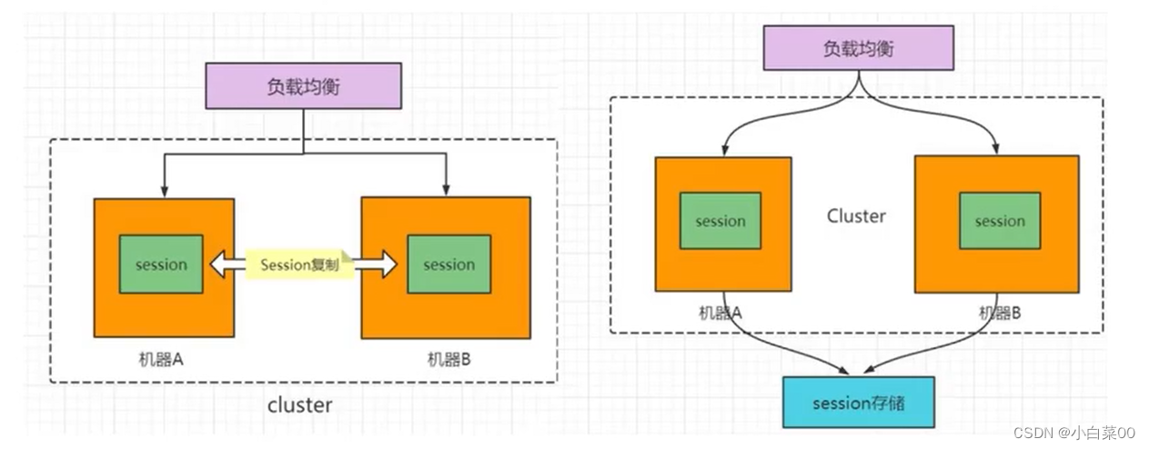
Session and cookie, token and storage

Mysql数据类型

What has Amazon cloud technology done right to become the leader of cloud AI services for three consecutive years?
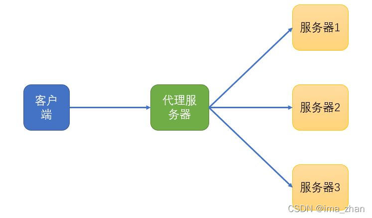
Understanding of forward proxy and reverse proxy

The third experiment OSPF

Longitude and latitude and its transformation with coordinate system
![[paper notes] robot dynamic tracking and grasping method based on online prediction and planning](/img/0f/ca7f3cd3332069185a2dad397766b4.png)
[paper notes] robot dynamic tracking and grasping method based on online prediction and planning
随机推荐
[PMP learning notes] Chapter 1 Introduction to PMP System
Recyclerview computehorizontalscrollextend computehorizontalscrollrange computehorizontalscroll for calculating the sliding distance
Solve the problem phpstudy failed to import the database
Analysis of direction finding error of multi baseline interferometer system
The difference between abstract classes and interface interfaces
Network Security Learning (XIII) data link layer
Madness. MySQL learning.
js正则表达式匹配ip地址(ip地址正则表达式验证)
uvm_ HDL -- implementation of DPI in UVM (4)
AI首席架构师12-AICA-工业生产过程优化场景下产业落地解析
Summary of common methods of string:
QT add mouse event to control
TFrecord写入与读取
Tfrecord write and read
Expression of directional signal -- complex exponential signal
CUDA environment construction
Summary of my 2020 online summer camp
Similarities and differences between equals and "= ="
赋能合作伙伴,亚马逊云科技如何落地“扶上马,送一程”?
Common software shortcuts