当前位置:网站首页>Blinn Phong reflection model
Blinn Phong reflection model
2022-06-11 09:02:00 【Crmeb Zhongbang Technology】

Preface
In this chapter , Realize the interaction between light and object surface . The purpose is to add shading function in the rendering pipeline , Therefore, only the most basic local illumination model is discussed here . Different from global illumination , In the local illumination model , The color value of the shaded point depends only on the material properties of the shaded point surface 、 The local geometric properties of the surface and the location and properties of the light source , It has nothing to do with other surfaces in the scene .
Rendering process and scene definition
Because global illumination is not considered , Only consider the light emitted from the light source , Specifically, only one single interaction between the light source and the surface is considered . So this problem can be divided into two independent parts :
- Define the lights in the scene ( Only point light sources are introduced here )
- Define a reflection model that describes the interaction between materials and light (phong And Blinn-Phong Reflection model ).
First, from the light emitted by a point light source , Because the observer sees only the light that starts from the light source and finally reaches his eyes . In other words, it can be divided into two situations :
- Or this light will go directly into the observer's eyes after starting from the light source , What you see at this time is the color of the light source .
- Either this ray passes through a complex route and interacts with the objects in the scene many times ( Only consider it once ), Then enter the observer's eyes , What you see at this time is the interaction between the light source and the surface material .

stay webgl in , The projection plane is often used instead of the observer . conceptually , The part of the projection plane located in the clipping window is mapped to the display , Therefore, the projection plane can be divided into many small rectangles with straight lines , Each small rectangle corresponds to a pixel on the screen . In other words, the color of the light source and the object surface determines the color of one or more pixels .
Reflected light type
After studying physics in junior high school, I know , Basically divided into 3 There are different types of reflected light .
- The ambient light : Its characteristic is to make the scene get uniform lighting , It is the result of multiple interactions between light and scene objects . Here, simply set it as a constant to simulate .
- Diffuse light : It is characterized by scattering incident light in all directions , And the intensity of light scattered in all directions is equal , Therefore, the reflected light seen by observers at different positions is the same .
- The mirror reflects light : Its characteristic is that it looks shiny , Because the direction of most of the reflected light is very close to the direction of the reflection angle . The direction of the reflected light follows the law that the incident angle is equal to the reflection angle .
For the sake of simplicity , The illumination mentioned below is to establish a point , This point is the coloring point . And this point should be on the surface of the object , So the illumination of this point is the shading effect of the light source on this point . 
As shown in the figure , First, let's define some unit vectors :
- The normal of the shaded point n
- The direction of the light l
- Camera observation direction v
- Some parameters of the object surface
Light propagation and energy conservation
Light will decay in the process of propagation .

For example, in the beginning, the light is concentrated on a unit ball , That is, the innermost ball , At this point, the energy received by each point on the ball is the energy of light divided by the area of the ball .
When light travels to a radius of r On the ball , That is, when the outermost ball . According to the law of conservation of energy , Each point on the outermost ball receives less energy than , According to the formula, the energy received by the object surface is inversely proportional to the square of the distance of light propagation .
That is to say, the energy of the light received by the coloring point should be calculated , To calculate the distance from the light to the shading point .
Phong Reflection model
The reflection model is composed of Phong First of all . Not only the simulation efficiency is very high, but also the practical effect is very good , So that it can get a good rendering effect for a variety of lighting conditions and material properties .
Phong The reflection model takes into account the three interactions described above : The ambient light 、 Diffuse and specular reflection . For each color component , All have independent ambient light components 、 Diffuse light component and specular light component . Finally, add these three components to form the final color .
Use 4 A vector to calculate the shading points p The color value of . The unknown is the reflection vector r, and r Can be n and l affirmatory

Ambient light reflection
Ambient light intensity at all points on the surface LaL_{a}La It's all the same . Part of the ambient light is absorbed by the surface , Another part is reflected by the surface , The intensity of the reflected part is determined by the ambient light reflection system kak_{a}ka, So at this time RaR_{a}Ra=kak_{a}ka. among 0 <= kak_{a}ka <= 1.
therefore IaI_{a}Ia = kak_{a}ka * LaL_{a}La
Code implementation
In the code , Adding ambient light is very simple , Just set a small constant and multiply it by the color of the object
void main () { vec3 ambient = 0.05 * color;} Copy code Diffuse reflection
When a beam of parallel incident light hits a rough surface , The surface reflects light in all directions . 
It can be seen that there is a certain angle between the plane normal and the illumination direction , And according to the different included angles, the shading obtained by coloring points is different .

If the energy of each light is equal . Analyze the figure on the left , It can be seen that when the object surface is perpendicular to the direction of light , Will receive all 6 Root light . In the middle picture, the object is rotated to a certain angle , Only... Can be received 3 Root light , Logically, the surface of this object should be darker than the left .
So the brightness of the coloring point is related to the lighting direction l And the normal of the object surface n The included angle of is related . And in reality, we can also observe , For example, the earth's four seasons have different temperatures , That is, the illumination direction is related to the angle of the surface normal .
This relationship is famous Lamber's consine law The laws of : The light direction is proportional to the cosine of the surface normal direction :
cosθ=l∗ncosθ = l * ncosθ=l∗n
So diffuse reflection is also called Lambertian Shading:
First define the intensity of light I, When light reaches the surface of an object, the energy is I/r2I / r^2I/r2. How much light is absorbed is calculated according to the cosine of the included angle , This cosine is calculated from the point multiplication of the illumination vector and the normal vector .
Ld=kd(I/r2)max(0,n∗l)L_d = k_d(I / r^2)max(0, n * l)Ld=kd(I/r2)max(0,n∗l)
as for max(0, n * l) It means , Exclude the case where the cosine is negative . Because in real life ( When the surface is opaque ), It is impossible for light to illuminate the surface of an object from a negative angle . This happens , Just assign 0.
as for k, It's an absorption coefficient . It shows how much light is absorbed by the surface of the object , How much light is reflected . When kd=1k_d=1kd=1 when , That is, the surface of the object does not absorb light at all , All reflected out . 
Code implementation
In the code , The normal vector is known
const aNormal = gl.getAttribLocation(program, 'aNormal');gl.vertexAttribPointer(aNormal, 3, gl.FLOAT, gl.FALSE, fsize * 8, fsize * 3);gl.enableVertexAttribArray(aNormal); Copy code Passed from vertex shader to clip shader
// Vertex shader attribute vec3 aNormal;varying vec3 Normal;void main () { Normal = aNormal; ...}// Fragment Shader varying vec3 Normal;void main () { // Normalize vec3 norm = normalize(Normal);} Copy code The incoming and outgoing vector is calculated from the pixel position and the light source direction , The position of the pixel is also known as the vertex , The position of the light source is uniform uniform Variables store
// Vertex shader attribute vec3 aPos;varying vec3 FragPos;void main () { FragPos = aPos; ...}// Fragment Shader varying vec3 FragPos;uniform vec3 lightPos;void main () { vec3 lightDir = normalize(lightPos - FragPos);} Copy code Finally, the diffuse reflection component is calculated according to the formula
// Fragment Shader void main () { float diff = max(dot(norm, lightDir), 0.0); vec3 diffuse = diff * color;} Copy code Specular reflection
When we look at shiny objects, we see highlights . These highlights usually show different colors from ambient and diffuse reflections . And contrary to the fact that the diffuse surface is rough , The specular surface is smooth . The smoother the surface , The closer it is to the mirror , The more the reflected light is concentrated near an angle .
Phong An approximate model is proposed , When considering specular reflection , Think of the surface as smooth . The intensity of the light the observer sees depends on the direction of the reflected light r And the direction of the observer v The angle between the two α.
Ls=ksLscospαL_s = k_sL_scos^pαLs=ksLscospα
Where the coefficient ksk_sks(0 <= ksk_sks <= 1) Indicates how much of the incident specular reflected light is reflected . Index p Is the specular coefficient . As can be seen from the figure below , When p increases , The reflected light is increasingly concentrated near the reflection angle of the ideal reflector . 
When not p when ( namely p=1), From the perspective of reflection, we are 60 Look at the color dot when you're degrees , It's reasonable to say that it's very biased , But you can still see the highlights . That's not reasonable , Because in reality, you can only see highlights when you are very close , A little farther away, you can't see . That's why we add an index to normalize it .
Phone The advantage of the reflection model is , If you've put r and v Normalized to the unit vector , Then the specular reflection component can be calculated by point product operation just like diffuse reflection :
Ls=ksLsmax((r∗v)p,0)L_s = k_sL_smax((r * v)^p, 0)Ls=ksLsmax((r∗v)p,0)
Next, just calculate the reflection vector r that will do !
Reflection angle calculation
The normal vector is given , Using the normal vector n And the incident vector l You can calculate the reflection angle . Ideal specular reflection has a good feature : The angle of incidence is equal to the angle of reflection . As shown in the figure : 
The angle of incidence is the angle between the normal vector and the incidence vector , The reflection angle is the angle between the normal vector and the reflected light . In the plane , Only one reflection direction can satisfy the condition that the incident angle is equal to the reflection angle . But not in three-dimensional space , Because there are countless directions where the incident angle is equal to the reflection angle . So add a condition : A point on the surface p, Incident light and reflected light must be in the same plane . These two conditions can be determined by n and l determine r.
hypothesis l and n It's already a unit vector :
|l| = |n| = 1.
It is also assumed that r It's also a unit vector :
|r| = 1
If θIθ_IθI=θrθ_rθr that
cosθicosθ_icosθi = cosθrcosθ_rcosθr
Using dot product operation, we can get :
cosθicosθ_icosθi = l * n = cosθrcosθ_rcosθr = n * r
The coplanar condition means that r It's written in l and n The linear combination of :
r = αl + βn(1)
Both sides of the equal sign are equal to n Do some product to get the equation (2):
n * r = αl * n + β = l * n(2)
because r It's the unit vector , So substitute it into the equation (1) You can get the equation (3):
1 = r * r = α2α^2α2 + 2αβl * n + β2β^2β2(3)
Combine the equation (2) And equation (3) Available
r = 2(l * n))n - l
Code implementation
The above formula for calculating the reflection angle , stay glsl There is a built-in function in reflect Realized . So the implementation in the code is very simple , The line of sight vector is also known .
// Fragment Shader uniform vec3 viewPos;void main () { vec3 viewDir = normalize(viewPos - FragPos); vec3 reflectDir = reflect(-lightDir, norm); vec3 specular = vec3(0.3) * pow(max(dot(viewDir, reflectDir), 0.0), 8.0);} Copy code Phong Reflection model results
Put the above 3 The sum of the two components is Phong Reflection model
L=La+Ld+LsL = L_a + L_d + L_sL=La+Ld+Ls
=kaIa+kd(I/r2)max(0,n∗l)+ksLsmax((r∗v)p,0)= k_aI_a + k_d(I/r^2)max(0, n*l) + k_sL_smax((r * v)^p, 0)=kaIa+kd(I/r2)max(0,n∗l)+ksLsmax((r∗v)p,0)
gl_FragColor = vec4(ambient + diffuse + specular, 1.0); Copy code The renderings are as follows

Phong The reflection model not only has a good approximation to the real illumination , And the performance is also very high . But its specular reflection will have problems in some cases , Especially when the reflectance of the object is very low , Can cause large areas of highlights .
The reason for this problem is that the angle between the observation vector and the reflection vector cannot be greater than 90 degree . If the dot product is negative , The specular reflection becomes 0. You might think , When the angle between light and line of sight is greater than 90 When the degree of , It should not receive any light . This idea only applies to diffuse reflection .
But in specular reflection , The measured angle is not the angle between the light source and the normal , It's the angle between the line of sight and the reflected light vector , Here's the picture . 
On the right , The angle between the line of sight and the reflection direction is significantly greater than 90 degree , In this case, the mirror light component is 0. This is OK in most cases , Because the observation direction is very far from the reflection direction . However , When the reflectance of an object is very small , The specular highlight radius it produces is sufficient for these opposite rays to have a large enough impact on the brightness , In this case, their contribution to the specular light component cannot be ignored .
And the reflection angle is difficult to calculate .
So in Phong On the basis of ,Blinn Expand on this , Introduced Blinn-Phong Reflection model .
Blinn-Phong Reflection model
This model is similar to Phong The difference between the models is only in the treatment of specular light components .Blinn-Phong The reflection model no longer depends on the reflection angle , Instead, we use a half range vector , That is, the unit vector in the direction of half the angle between the light and the line of sight .
Half range vector
When the viewing direction is close to the specular reflection direction , The normal direction of the object surface is close to the half range vector .

The so-called half range vector is the sum of the illumination direction vector and the observation direction vector according to the parallelogram rule and then divided by its length .
h=(v+l)/∣v+l∣h = (v + l) / |v + l|h=(v+l)/∣v+l∣
h And n Proximity means v and r near , This is it. Blinn-Phong What's special about the model . because r and v The included angle of is difficult to calculate , With this little trick , The calculation is much simpler .
Almost the same as diffuse reflection , It's just that the angle between the illumination direction and the normal direction is replaced by the angle between the half-way vector and the normal direction
Ls=ks(I/r2)max(0,n∗h)pL_s = k_s(I / r^2)max(0, n * h)^pLs=ks(I/r2)max(0,n∗h)p
Code implementation
vec3 halfwayDir = normalize(lightDir + viewDir);vec3 specular = vec3(0.3) * pow(max(dot(norm, halfwayDir), 0.0), 32.0); Copy code The renderings are as follows

Last
If you think this article is of little help to you , Point a praise . Or you can join my development communication group :1025263163 Learn from each other , We will have professional technical questions and answers
If you think this article is useful to you , Please give our open source project a little bit star:http://github.crmeb.net/u/defu Thank you for !
PHP Learning manual :https://doc.crmeb.com
Technical exchange forum :https://q.crmeb.com
边栏推荐
- Erreur de démarrage MySQL "BIND on TCP / IP Port: Address already in use"
- Matlab learning 9- nonlinear sharpening filter for image processing
- multiplication table
- How many items should the indoor intumescent fire retardant coating meet according to BS 476-21 fire resistance standard?
- SAP material master data archiving
- File system check of the root filesystem failed
- SAP abap 数据类型与数据对象
- 剑指 Offer 18. 删除链表的节点
- Typescript high level feature 1 - merge type (&)
- 小型制氧机解决方案PCBA电路板开发
猜你喜欢

【新手上路常见问答】关于数据可视化

端口占用问题,10000端口

shell脚本之sed详解 (sed命令 , sed -e , sed s/ new / old / ... )

Which Apple devices support this system update? See if your old apple device supports the latest system

typescript高阶特性一 —— 合并类型(&)

kubelet Error getting node 问题求助

M1 chip guide: M1, M1 pro, M1 Max and M1 ultra

机器学习笔记 - 卷积神经网络备忘清单
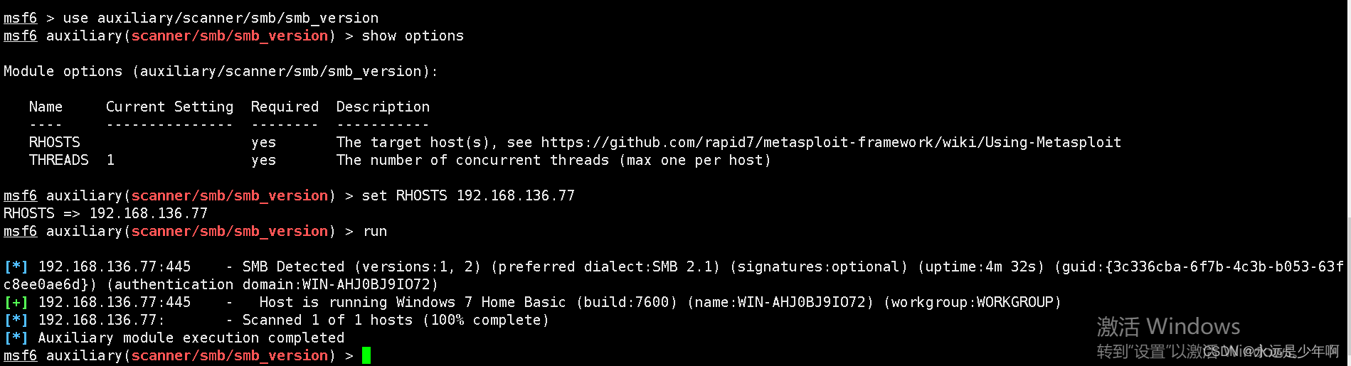
MSF基于SMB的信息收集

vagrant 安装踩坑
随机推荐
Flutter开发日志——路由管理
PHP uploading large files for more than 40 seconds server 500
844. compare strings with backspace
【方案开发】红外体温计测温仪方案
86. separate linked list
【新手上路常见问答】关于数据可视化
leveldb简单使用样例
工厂出产流程中的这些问题,应该怎么处理?
面試題 02.02. 返回倒數第 k 個節點
445. adding two numbers II
山东大学增强现实实验四
EN 45545-2:2020 T11 smoke toxicity test
Complete ES6 questions
SAP abap内表分类与增删改查操作
E. Zoom in and zoom out of X (operator overloading)
从企业评价的方历来看ERP软件成功与失利
83. delete duplicate elements in the sorting linked list
Notes on MySQL core points
C language printing heart
PHP解决中文显示乱码