当前位置:网站首页>Halcon 3D 1 Reading 3D data
Halcon 3D 1 Reading 3D data
2022-06-12 05:36:00 【Σίσυφος one thousand and nine hundred】
One 、 Read 3d data
read_object_model_3d('D:/work/pcl_workplaces/PCL_test/bunny.pcd', 'mm', 'convert_to_triangles', 'true', ObjectModel3D, Status)
*FileName: file name ,halcon Support for multiple 3d Data format reading , Include  .off, .ply, .dxf, .om3, .obj, .stl Equiform .
*         1).om3: For 3D object models HALCON Format . Files in this format can be created by write_object_model_3d To write . The default file extension for this format is ’om3’.
*         2).ply: Polygon file format ( It is also the Stanford triangle format ). This is a simple format , It can be saved 3D spot 、 Point normal 、 polygon 、 Color information and point based extended attributes .HALCON Support this format ASCII And binary versions . If the file to be read contains unsupported information , be ASCII The file will ignore the extra data , Read only supported data . For binary versions of this format , In this case, an error is returned , And will not return the object model . The default file extension for this format is ’ply’.
*         3).off: Object file format . This is a simple one based on ascii The format of , It can be saved 3D Points and polygons . Binary is not supported OFF Format . The default file extension for this format is ’off’.
*         4).dxf: AUTOCAD Format ,  The default file extension for this format is “dxf”. When reading DXF When you file , Output parameters Status Contains information about the 3D Information about the number of faces , If necessary , There is also a warning section DXF The file cannot be interpreted .
*         5).obj: OBJ File format , Also known as “ Wave front OBJ Format ”. This is a base ascii The format of , It can be saved 3D spot , polygon , normal , Texture coordinates , Materials and other information .HALCON Support points (“v” Line ) And polygon faces (“f” Line ). Other entities will be ignored . The default file extension for this format is ’obj’.
*         6) .stl:  Store triangles and their normals . However , because HALCON 3D The object model does not support triangle normals , So only the triangle is read and the triangle normal is ignored . if necessary , Recalculate normals from triangles .HALCON Read the... In this format ASCII And binary versions . If set ’stl’, HALCON This type will be detected automatically . Set type to ’stl_binary’ or ’stl_ascii’ The appropriate format will be enforced . The default file extension for this format is ’stl’.
*Scale: Unit of measurement , Include  ‘m’, ‘cm’, ‘mm’, ‘microns’, ‘um’, ‘nm’, ‘km’, ‘in’, ‘ft’, ‘yd’, 1.0, 0.01, 0.001, 1.0e-6, 0.0254, 0.3048, 0.9144
*Scale Parameter defines the size of the file . for example , If the parameter is set to ’mm’, It is assumed that all units in the file have units ’mm’, And by working with 1e-3 Multiply to convert it to the usual HALCON-internal Company ’m’. therefore ,“100 mm ” The value of a “0.1 rice ”. perhaps , You can pass a scaling factor to Scale, Multiply it by all the coordinate values found in the file .
*GenParamName, GenParamValue:
* Parameter names include :‘convert_to_triangles’, ‘file_type’, ‘invert_normals’, ‘max_approx_error’, ‘min_num_points’, ‘xyz_map_height’, ‘xyz_map_width’.
* Parameter values include : ‘true’,      ‘false’,     1, 0,
*file_type  Include : ‘om3’, ‘off’, ‘ply’, ‘dxf’, ‘obj’, ‘stl’, ‘stl_binary’, ‘stl_ascii’.
*convert_to_triangles: Convert all faces to triangles . If the parameter is set to ’true’, Then all faces read from the file will be converted to triangles .
*invert_normals: Reverses the normal and face directions . If the parameter is set to “true”, Then all normal and face directions are reversed .
*max_approx_error  And  min_num_points:DXF-specific parameters
*‘xyz_map_height’: For reading 3D Object model creation mapping , Assign the image coordinates to each read 3D spot , Such as xyz_to_object_model_3d As shown in . Assume that the read file contains 3D spot . The passed value is used as the width of the image . The height of the image is calculated automatically . If this parameter is set , be object_model_3d_to_xyz have access to ’from_xyz_map’ Method projection read 3D The object model . Only two parameters can be set ’xyz_map_width’ and ’xyz_map_height’ One of them .
*‘xyz_map_width’: Such as ’xyz_map_width’, But suppose 3D The dots are arranged in columns . The width of the image is calculated automatically . Only two parameters can be set ’xyz_map_width’ and ’xyz_map_height’ One of them .
*ObjectModel3D: Model handle
*Status: State information
Two 、 According to the model
visualize_object_model_3d (WindowHandle, ObjectModel3D, [], [], [], [], Message, [], Instructions, PoseOut)
*WindowHandle: Form identifier .
*ObjectModel3D:3d Model .
*CamParam: Camera parameters , for example :StartCamPar := [0.016, 0, 0.0000074, 0.0000074, 326, 247, 652, 494]
*PoseIn: Initial pose .
*GenParamName: Parameter name , Used for calling each function module , You can choose at will . Include the following parameters :‘alpha’, ‘attribute’, ‘color’, ‘colored’, ‘disp_background’, ‘disp_lines’, ‘disp_normals’, ‘disp_pose’, ‘inspection_mode’, ‘intensity’, ‘intensity_red’, ‘intensity_green’, ‘intensity_blue’, ‘light_position’, ‘light_ambient’, ‘light_diffuse’, ‘line_color’, ‘line_width’, ‘lut’, ‘max_num_selectable_models’, ‘normal_color’, ‘point_size’.
*           Common parameters :
*          1.colored: Show in different colors 3d Model , The value can be set to 3, 6, or 12.
*          2.attribute: Clear choice 3D How the object model is visualized ,Values: ‘auto’, ‘faces’, ‘primitive’, ‘points’, ‘lines’.
*          3. color:  Set up 3D The color of the object model . The available colors can be represented by the operator query_color Inquire about . Besides , The color can be specified as RGB A triple , In the form of ’#rrggbb’, among ’rr’、‘gg’ and ’bb’ Respectively ’00’ and ’ff’ The hexadecimal number between .Values: ‘red’, ‘green’, ….
*          4.alpha: Transparency of 3D object model . Set the transparency to less than 1.0 Of 3D The object model may increase significantly display_scene_3d and render_scene_3d Running time of . value : Floating point values in 0.0( Completely transparent ) and 1.0( Completely opaque ) Between .
*          5.disp_pose: Mark , If 3D The pose of the object model should be visualized ,Values: ‘true’ or ‘false’.
*          6.disp_normals: Mark , If 3D The normals of the object model should be visualized ,Values: ‘true’ or ‘false’.
*          7.normal_color: If ’disp_normals’ Set to ’true’, The normal color is displayed .
*          8.lut:  Query table . Settings will ’color_attrib’ The value of the property set is converted to the value of the color LUT, see set_lut To get available lut. If ’lut’ Set to ’default’ Any value other than ,‘color’ Will be ignored .
*          9.color_attrib: For pseudo color visualization point Name of property .( Pseudo color : The color of each pixel is not directly determined by the value of each basic color component , It's actually using pixels as a palette (Palettes) Or color lookup table (Color Look-Up Table,CLUT) Table entry address of , According to the address, you can find out the actual R、G、B The strength of the value , If the color in the image does not exist in the palette or color lookup table , The palette will match with the closest color . By finding out R、G、B The color produced by the intensity value is not the real color of the image itself , So it is called pseudo color .) If the property is set , It shows 3D The color of the point is determined by the attribute value of the point and the current setting LUT decision ( See ’ LUT ‘). such , You can visualize attributes with false colors .
*           Example : If ’color_attrib’ Set to ’coord_z’, and ’lut’ Set to ’color1’, be z The color coding of the coordinates will be from red to blue . If ’lut’ Set to ’default’, The attribute value will be used to scale the parameter ’color’ Set the color .
*           If ’lut’ Set to different values , The attribute values of all points are internally scaled to [0,255], And used as lut The input value of the function . The mapping is also determined by the parameters ’color_attrib_start’ and ’color_attrib_end’( See below ) control .
*           If the face is shown , Their colors will be interpolated between the colors of the corners .
*           value :‘none’, ‘&distance’, ‘coord_x’, ‘coord_y’, ‘coord_z’, User defined point attributes , Or any other available point attributes .
*          10.color_attrib_start’,'color_attrib_end: Use ’color_attrib’ Set the range of attribute values .
*          ‘color_attrib_start’ and ’color_attrib_end’ The attribute values between are scaled to the selected LUT The beginning and the end of . Attribute values outside the selected range will be cut . This allows a fixed color mapping to be used , It is not distorted by outliers .
*           If set to ’auto’, Then the minimum attribute value is mapped to LUT The beginning of , The maximum attribute value is mapped to LUT Ending , Unless ’color_attrib’ yes ’normal_x’、‘normal_y’ or ’normal_z’. under these circumstances ,start and end Will be automatically set to -1 and 1. You can enter a starting value higher than the final value . This will actually flip the used LUT.
*          Values: 0, 0.1, 1, 100, 255, …
*          11.max_num_selectable_models: Selectable and handled separately 3D Number of object models .
*          12.inspection_mode: Flag that controls the initial state of the check mode .
*           If ’inspection_mode’ Set to ’standard’, The rotation center is fixed at the center of the display object . In this mode , The center of rotation consists of a vertical cross (+) Express . This model is especially suitable for getting the impression of the whole object .
*           If ’inspection_mode’ Set to ’surface’, The rotation center is fixed at the center of the window , On the surface of the display object . In this mode , The center of rotation consists of a diagonal fork (x) Express . This mode is especially suitable for the detailed inspection of the object surface . Since point clouds do not provide surface information , Therefore, it is not suitable for point cloud detection .
*           Be careful , The trackball itself remains in the center of the image , No matter which inspection mode is selected . Also note that , In the visualization process , adopt Ctrl + Alt + The left mouse button can switch the inspection mode interactively ( See above ).Values: ‘standard’ or ‘surface’
*Message  3D Model name
*Label
*Information :  Operation instructions
*PoseOut: Output
3、 ... and 、 Code shows
dev_close_window ()
dev_open_window (0, 0, 400, 500, 'black', WindowHandle)
* Read point cloud ply file
read_object_model_3d('D:/work/pcl_workplaces/PCL_test/bunny.pcd', 'mm', 'convert_to_triangles', 'true', ObjectModel3D, Status)
*FileName: file name ,halcon Support for multiple 3d Data format reading , Include  .off, .ply, .dxf, .om3, .obj, .stl Equiform .
*         1).om3: For 3D object models HALCON Format . Files in this format can be created by write_object_model_3d To write . The default file extension for this format is ’om3’.
*         2).ply: Polygon file format ( It is also the Stanford triangle format ). This is a simple format , It can be saved 3D spot 、 Point normal 、 polygon 、 Color information and point based extended attributes .HALCON Support this format ASCII And binary versions . If the file to be read contains unsupported information , be ASCII The file will ignore the extra data , Read only supported data . For binary versions of this format , In this case, an error is returned , And will not return the object model . The default file extension for this format is ’ply’.
*         3).off: Object file format . This is a simple one based on ascii The format of , It can be saved 3D Points and polygons . Binary is not supported OFF Format . The default file extension for this format is ’off’.
*         4).dxf: AUTOCAD Format ,  The default file extension for this format is “dxf”. When reading DXF When you file , Output parameters Status Contains information about the 3D Information about the number of faces , If necessary , There is also a warning section DXF The file cannot be interpreted .
*         5).obj: OBJ File format , Also known as “ Wave front OBJ Format ”. This is a base ascii The format of , It can be saved 3D spot , polygon , normal , Texture coordinates , Materials and other information .HALCON Support points (“v” Line ) And polygon faces (“f” Line ). Other entities will be ignored . The default file extension for this format is ’obj’.
*         6) .stl:  Store triangles and their normals . However , because HALCON 3D The object model does not support triangle normals , So only the triangle is read and the triangle normal is ignored . if necessary , Recalculate normals from triangles .HALCON Read the... In this format ASCII And binary versions . If set ’stl’, HALCON This type will be detected automatically . Set type to ’stl_binary’ or ’stl_ascii’ The appropriate format will be enforced . The default file extension for this format is ’stl’.
*Scale: Unit of measurement , Include  ‘m’, ‘cm’, ‘mm’, ‘microns’, ‘um’, ‘nm’, ‘km’, ‘in’, ‘ft’, ‘yd’, 1.0, 0.01, 0.001, 1.0e-6, 0.0254, 0.3048, 0.9144
*Scale Parameter defines the size of the file . for example , If the parameter is set to ’mm’, It is assumed that all units in the file have units ’mm’, And by working with 1e-3 Multiply to convert it to the usual HALCON-internal Company ’m’. therefore ,“100 mm ” The value of a “0.1 rice ”. perhaps , You can pass a scaling factor to Scale, Multiply it by all the coordinate values found in the file .
*GenParamName, GenParamValue:
* Parameter names include :‘convert_to_triangles’, ‘file_type’, ‘invert_normals’, ‘max_approx_error’, ‘min_num_points’, ‘xyz_map_height’, ‘xyz_map_width’.
* Parameter values include : ‘true’,      ‘false’,     1, 0,
*file_type  Include : ‘om3’, ‘off’, ‘ply’, ‘dxf’, ‘obj’, ‘stl’, ‘stl_binary’, ‘stl_ascii’.
*convert_to_triangles: Convert all faces to triangles . If the parameter is set to ’true’, Then all faces read from the file will be converted to triangles .
*invert_normals: Reverses the normal and face directions . If the parameter is set to “true”, Then all normal and face directions are reversed .
*max_approx_error  And  min_num_points:DXF-specific parameters
*‘xyz_map_height’: For reading 3D Object model creation mapping , Assign the image coordinates to each read 3D spot , Such as xyz_to_object_model_3d As shown in . Assume that the read file contains 3D spot . The passed value is used as the width of the image . The height of the image is calculated automatically . If this parameter is set , be object_model_3d_to_xyz have access to ’from_xyz_map’ Method projection read 3D The object model . Only two parameters can be set ’xyz_map_width’ and ’xyz_map_height’ One of them .
*‘xyz_map_width’: Such as ’xyz_map_width’, But suppose 3D The dots are arranged in columns . The width of the image is calculated automatically . Only two parameters can be set ’xyz_map_width’ and ’xyz_map_height’ One of them .
*ObjectModel3D: Model handle
*Status: State information


Instructions[0] := 'Rotate: Left button'
Instructions[1] := 'Zoom:   Shift + left button'
Instructions[2] := 'Move:   Ctrl  + left button'

Message := 'Bunny3D PointCloud'
* Virtualize the model and display
visualize_object_model_3d (WindowHandle, ObjectModel3D, [], [], [], [], Message, [], Instructions, PoseOut)
*WindowHandle: Form identifier .
*ObjectModel3D:3d Model .
*CamParam: Camera parameters , for example :StartCamPar := [0.016, 0, 0.0000074, 0.0000074, 326, 247, 652, 494]
*PoseIn: Initial pose .
*GenParamName: Parameter name , Used for calling each function module , You can choose at will . Include the following parameters :‘alpha’, ‘attribute’, ‘color’, ‘colored’, ‘disp_background’, ‘disp_lines’, ‘disp_normals’, ‘disp_pose’, ‘inspection_mode’, ‘intensity’, ‘intensity_red’, ‘intensity_green’, ‘intensity_blue’, ‘light_position’, ‘light_ambient’, ‘light_diffuse’, ‘line_color’, ‘line_width’, ‘lut’, ‘max_num_selectable_models’, ‘normal_color’, ‘point_size’.
*           Common parameters :
*          1.colored: Show in different colors 3d Model , The value can be set to 3, 6, or 12.
*          2.attribute: Clear choice 3D How the object model is visualized ,Values: ‘auto’, ‘faces’, ‘primitive’, ‘points’, ‘lines’.
*          3. color:  Set up 3D The color of the object model . The available colors can be represented by the operator query_color Inquire about . Besides , The color can be specified as RGB A triple , In the form of ’#rrggbb’, among ’rr’、‘gg’ and ’bb’ Respectively ’00’ and ’ff’ The hexadecimal number between .Values: ‘red’, ‘green’, ….
*          4.alpha: Transparency of 3D object model . Set the transparency to less than 1.0 Of 3D The object model may increase significantly display_scene_3d and render_scene_3d Running time of . value : Floating point values in 0.0( Completely transparent ) and 1.0( Completely opaque ) Between .
*          5.disp_pose: Mark , If 3D The pose of the object model should be visualized ,Values: ‘true’ or ‘false’.
*          6.disp_normals: Mark , If 3D The normals of the object model should be visualized ,Values: ‘true’ or ‘false’.
*          7.normal_color: If ’disp_normals’ Set to ’true’, The normal color is displayed .
*          8.lut:  Query table . Settings will ’color_attrib’ The value of the property set is converted to the value of the color LUT, see set_lut To get available lut. If ’lut’ Set to ’default’ Any value other than ,‘color’ Will be ignored .
*          9.color_attrib: For pseudo color visualization point Name of property .( Pseudo color : The color of each pixel is not directly determined by the value of each basic color component , It's actually using pixels as a palette (Palettes) Or color lookup table (Color Look-Up Table,CLUT) Table entry address of , According to the address, you can find out the actual R、G、B The strength of the value , If the color in the image does not exist in the palette or color lookup table , The palette will match with the closest color . By finding out R、G、B The color produced by the intensity value is not the real color of the image itself , So it is called pseudo color .) If the property is set , It shows 3D The color of the point is determined by the attribute value of the point and the current setting LUT decision ( See ’ LUT ‘). such , You can visualize attributes with false colors .
*           Example : If ’color_attrib’ Set to ’coord_z’, and ’lut’ Set to ’color1’, be z The color coding of the coordinates will be from red to blue . If ’lut’ Set to ’default’, The attribute value will be used to scale the parameter ’color’ Set the color .
*           If ’lut’ Set to different values , The attribute values of all points are internally scaled to [0,255], And used as lut The input value of the function . The mapping is also determined by the parameters ’color_attrib_start’ and ’color_attrib_end’( See below ) control .
*           If the face is shown , Their colors will be interpolated between the colors of the corners .
*           value :‘none’, ‘&distance’, ‘coord_x’, ‘coord_y’, ‘coord_z’, User defined point attributes , Or any other available point attributes .
*          10.color_attrib_start’,'color_attrib_end: Use ’color_attrib’ Set the range of attribute values .
*          ‘color_attrib_start’ and ’color_attrib_end’ The attribute values between are scaled to the selected LUT The beginning and the end of . Attribute values outside the selected range will be cut . This allows a fixed color mapping to be used , It is not distorted by outliers .
*           If set to ’auto’, Then the minimum attribute value is mapped to LUT The beginning of , The maximum attribute value is mapped to LUT Ending , Unless ’color_attrib’ yes ’normal_x’、‘normal_y’ or ’normal_z’. under these circumstances ,start and end Will be automatically set to -1 and 1. You can enter a starting value higher than the final value . This will actually flip the used LUT.
*          Values: 0, 0.1, 1, 100, 255, …
*          11.max_num_selectable_models: Selectable and handled separately 3D Number of object models .
*          12.inspection_mode: Flag that controls the initial state of the check mode .
*           If ’inspection_mode’ Set to ’standard’, The rotation center is fixed at the center of the display object . In this mode , The center of rotation consists of a vertical cross (+) Express . This model is especially suitable for getting the impression of the whole object .
*           If ’inspection_mode’ Set to ’surface’, The rotation center is fixed at the center of the window , On the surface of the display object . In this mode , The center of rotation consists of a diagonal fork (x) Express . This mode is especially suitable for the detailed inspection of the object surface . Since point clouds do not provide surface information , Therefore, it is not suitable for point cloud detection .
*           Be careful , The trackball itself remains in the center of the image , No matter which inspection mode is selected . Also note that , In the visualization process , adopt Ctrl + Alt + The left mouse button can switch the inspection mode interactively ( See above ).Values: ‘standard’ or ‘surface’
*Message  3D Model name
*Label
*Information :  Operation instructions
*PoseOut: Output
dev_clear_window ()
边栏推荐
- Quickly get PCA (principal component analysis) (principle code case)
- [daily question on niuke.com] two point search
- Legal liabilities to be borne by the person in charge of the branch
- 38. 外观数列
- 59 - I. maximum value of sliding window
- [road of system analyst] collection of wrong topics in software engineering chapters
- Introduction to audio alsa architecture
- The relation between virtual function and pure virtual function
- Object class not ended
- Stm32f4 ll library multi-channel ADC
猜你喜欢

Introduction to Internet Protocol

Automated test - dark horse headline test project

基于tensorflow的校园绿植识别

yolov5

SQL transaction

Codis 3. X expansion and contraction

20000 word detailed reptile knowledge reserve, basic exercises of data collection and cleaning (I) reference answers to the first song
![[getting to the bottom] five minutes to understand the combination evaluation model - fuzzy borde (taking the C question of the 2021 college students' numerical simulation national competition as an e](/img/2e/97310ec36aeb1fc1e9c82361141a36.jpg)
[getting to the bottom] five minutes to understand the combination evaluation model - fuzzy borde (taking the C question of the 2021 college students' numerical simulation national competition as an e
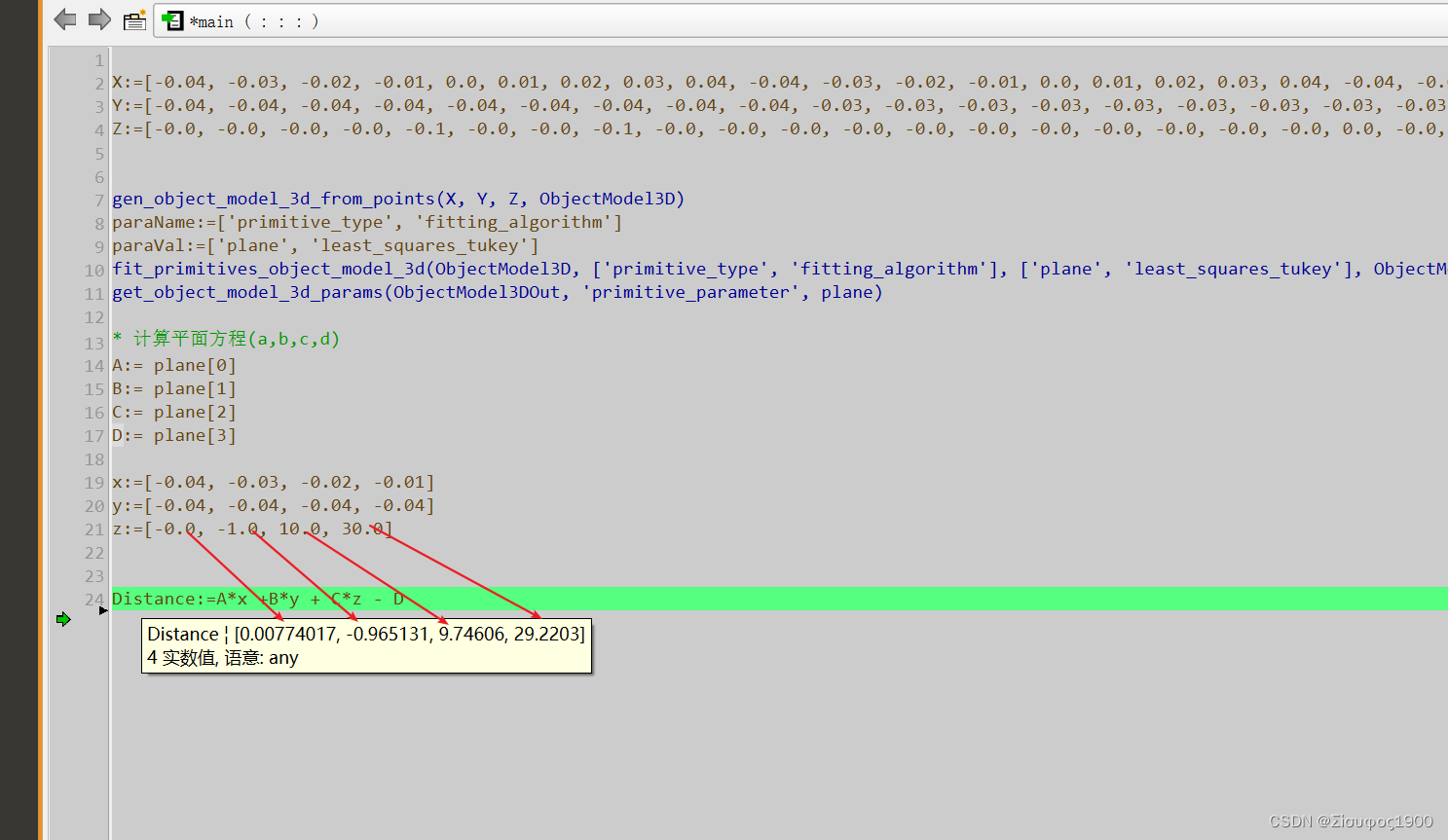
Halcon 用点来拟合平面

Test work summary - performance test indicators
随机推荐
XML参数架构,同一MTK SW版本兼容两套不同的音频参数
Nature | make an account of the new crown casualties in the world
31. stack push in and pop-up sequence
[grpc development] go language builds simple server and client
Servlet core
Please remove any half-completed changes then run repair to fix the schema history
[fastapi] use pycharm to configure and use environment variables for fastapi projects
Towards End-to-End Lane Detection: an Instance SegmentationApproach
Detailed analysis of the 2021 central China Cup Title A (color selection of mosaic tiles)
Details of FPGA syntax
Go interface implementation principle [advanced level]
SIM卡信号的驱动电流是多少mA,是否是可调节的?
Performance & interface test tool - JMeter
@Configurationproperties value cannot be injected
20. string representing numeric value
org. apache. ibatis. binding. BindingException: Invalid bound statement (not found)
29. print matrix clockwise
按键精灵的简单入门
flex/fixed上中下(移动端)
AddUser add user and mount hard disk