当前位置:网站首页>Axi protocol Basics
Axi protocol Basics
2022-06-11 17:03:00 【XPii】
AXI Protocol Basics
- 1、AXI brief introduction
- 2、AXI characteristic
- 3、AXI The overall structure
- 4、AXI Signals in the protocol
- 5、 host / Handshake process between slaves and READY and VALID Handshake signals
- 6、AXI Types of burst reads and writes 、 Calculation of read / write transaction address
- 6.1 A burst address cannot be crossed 4K The border .
- 6.2 The signal AWLEN Or signal ARLEN Specifies the number of data transmitted for each burst read / write .
- 6.3 ARSIZE Signal or AWSIZE The signal specifies the maximum number of bits of data transmitted per clock beat .
- 6.4 Three types of burst reading and writing
- 7、AXI Medium ID tags


1、AXI brief introduction
AXI(Advanced eXtensible Interface) It's a bus protocol , The agreement is ARM The company put forward AMBA(Advanced Microcontroller Bus Architecture)3.0 The most important part of the agreement , It's a high performance oriented 、 High bandwidth 、 Low latency on chip bus . Its address / The control and data phases are separate , Support data transmission with misalignment , At the same time in burst transmission , Just the first address , Simultaneously separate read and write data channels 、 It also supports significant transmission access and out of order access , And it's easier to do timing convergence .
2、AXI characteristic
- One way channel architecture , Information flow is transmitted only in one direction , Simplify the bridge between clock domains , Reduce the number of doors .
- By performing burst operations in parallel , Greatly improve the data throughput , Can complete the task in a shorter time , While meeting the requirements of high performance , Reduced power consumption .
- Independent address and data channel . Address and data channels are separated , Each channel can be optimized separately , The timing channel can be controlled as needed , Raise the clock frequency to the highest , And minimize the delay .
3、AXI The overall structure
- AXI The bus shares 5 The channels are read address channel 、write address channel 、read data channel 、 write data channel、 write response channel. every last AXI Transmission channels are unidirectional .
- The structure of the read transaction is as follows :

- The structure of the write transaction is as follows :

- this 5 Each independent channel contains an information signal and a two-way signal VALD、READY handshake mechanisms , The information source is through VALID Signal to indicate when the data and control information in the channel is valid . Source of destination READY Signal to indicate when data can be received . Both read and write data channels include a LAST The signal , Used to indicate the last data transferred by a transaction .
- The transmission address information and data are in VALID and READY Effective when it is high at the same time .
4、AXI Signals in the protocol
4.1 Global signal
| The signal | Source | describe |
|---|---|---|
| ACLK | Clock source | Global clockticks |
| ARESETn | Reset source | Global reset signal , Low level active |
4.2 Write the signal in the address channel
| The signal | Source | describe |
|---|---|---|
| AWID[3:0] | host | Write the address ID, This signal is written to the address signal group ID tag. |
| AWADDR[31:0] | host | Write the address |
| AWLEN[3:0] | host | Burst transmission length , This length determines the number of data transmitted by burst writing , That is, the amount of data transmitted in a burst is AWLEN + 1. |
| AWSIZE[2:0] | host | Burst transmission width , Number of data bytes transmitted per week . namely DATA_WIDTH/8 = 2AWSIZE . Referring to burst Number of bytes transferred at one time in the number of transfers , The specific value is equal to 2AWSIZE . So once burst The total number of bytes transmitted is equal to (burst The number of times ) * 2AWSIZE . |
| AWBURST[1:0] | host | Burst type , common FIXED,INCR,WRAP Three , Here is a detailed introduction . |
| AWLOCK[1:0] | host | Bus lock signal ,normal, exclusive, locked. |
| AWCACHE[3:0] | host | Cache type . This signal indicates the of the transaction bufferable、cacheable、write-through、write-back、allocate attributes Information . |
| AWVALID | host | Write address valid .1 = Address and control information valid ,0 = Invalid address and control information ; This signal will be maintained , until AWREADY Become high . |
| AWREADY | Slave | This signal is used to indicate that the slave is ready to receive address and control information .1 = The slave is ready ,0 = The slave is not ready . |
4.3 Write the signal in the data channel
| The signal | Source | describe |
|---|---|---|
| WID[3:0] | host | Write ID tag,WID The value of must match AWID The value of matches . |
| WDATA[31:0] | host | Writing data |
| WSTRB[3:0] | host | Write data valid byte line , It's used to show where 8bits The data is valid . |
| WLAST | host | Burst write the last data transmitted |
| WVALID | host | Write data valid signal ,1 = At this point, the data is valid ,0 = The data is invalid at this time . |
| WREADY | Slave | Write ready signal , Indicates whether the slave is ready to receive data .1 = The slave is ready ,0 = The slave is not ready . |
4.4 Write the signal in the response channel
| The signal | Source | describe |
|---|---|---|
| BID[3:0] | Slave | Respond to ID, This value must be the same as AWID Match the values of . |
| BRESP[1:0] | Slave | Write response . This signal indicates the status of the write transaction . Possible responses :OKAY、EXOKAY、SLVERR、DECERR. |
| BVALID | Slave | Write response is valid .1 = Write response is valid ,0 = Invalid write response . |
| BREADY | host | The host receives the response ready signal . This signal indicates whether the host can accept the response information .1 = Host ready ,0 = The host is not ready . |
4.5 Read the signal in the address channel
| The signal | Source | describe |
|---|---|---|
| ARID[3:0] | host | Respond to ID, This value must be the same as AWID Match the values of . |
| ARADDR[31:0] | host | Read the address . |
| ARLEN[3:0] | host | Burst transmission length , This length determines the number of data transmitted by burst writing , That is, the amount of data transmitted in a burst is AWLEN + 1. |
| ARSIZE[2:0] | host | Burst transmission width , Number of data bytes transmitted per week . namely DATA_WIDTH/8 = 2AWSIZE . |
| ARBURST[1:0] | host | Burst read type . common FIXED,INCR,WRAP Three , Here is a detailed introduction . |
| ARLOCK[1:0] | host | Bus lock signal ,normal, exclusive, locked. |
| ARCACHE[3:0] | host | Cache type . This signal indicates the of the transaction bufferable、cacheable、write-through、write-back、allocate attributes Information . |
| ARPROT[2:0] | host | Type of protection . |
| ARVALID | host | The read address is valid . The signal remains constant , until ARREADY For the high .1 = Address and control information valid ,0 = Invalid address and control information . |
| ARREADY | Slave | The slave is ready to receive the read address . Indicates that the slave is ready to receive the read address .1 = Slave ready ,0 = The slave is not ready . |
4.6 Read the signal in the data channel
| The signal | Source | describe |
|---|---|---|
| RID[3:0] | Slave | read ID tag.RID The value of must be the same as ARID Match the values of . |
| RDATA[31:0] | Slave | Reading data . |
| RRESP[1:0] | Slave | Read response signal . This signal indicates the status of the read transmission :OKAY、EXOKAY、SLVERR、DECERR. |
| RLAST | Slave | Read the last data transferred by the transaction . |
| RVALID | Slave | Read data effectively .1 = Read data effectively .0 = Invalid read data . |
| RREADY | host | Whether the host is ready to receive the read data signal .1 = Host ready ,0 = The host is not ready . |
5、 host / Handshake process between slaves and READY and VALID Handshake signals
5.1 VALID and READY Three relationships of signals
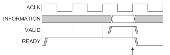
All 5 The channels use the same VALID/READY Hold the mobile phone to transmit data and control information . The transmission source generates VLAID Signal to indicate when data or control information is valid . And the destination source produces READY Signal to indicate that you are ready to receive data or control information . Transmission takes place in VALID and READY When the signal is high at the same time .
- VALID Get higher first READY After get higher . The sequence diagram is as follows , Data transmission occurs at the arrow .
- READY Get higher first VALID After get higher . The sequence diagram is as follows , Data transmission occurs at the arrow .
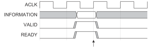
- VALID and READY The signal goes high at the same time . The sequence diagram is as follows , Data transmission occurs at the arrow .
5.2 The relationship between the five channels
Both relationships must be maintained :
- Read data must always follow the address associated with its data .
- The write response must always follow the last occurrence of the write transaction associated with it .
5.3 The relationship between handshake signals
5.3.1 Write the relationship between transaction handshake signals :
- The master cannot wait for the slave to give the first AWREADY or WREADY The signal is given after the signal AWVALID or WVLAID.
- The slave can wait for the signal AWVALID or WVALID Give after the signal is valid or both are valid AWREADY The signal .
- The slave can wait AWVALID or WVALID The signal is valid or both signals are valid WREADY The signal
5.3.2 Read the relationship between transaction handshake signals :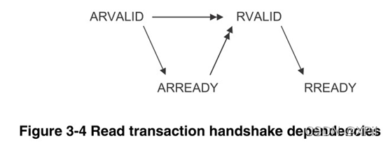
- The slave can ARVALID When it appears, it gives ARREADY The signal , You can also give ARREADY The signal , Wait for ARVALID The signal .
- The slave must wait ARVALID and ARREADY Only when the signals are valid can they be given RVALID The signal , Start data transfer .
6、AXI Types of burst reads and writes 、 Calculation of read / write transaction address
6.1 A burst address cannot be crossed 4K The border .
4k The biggest reason for boundary alignment is to define a page The size is 4kBytes, To better set each slave The interview of attribute, Just one slave Divide 4k Space .AXI A burst in the protocol cannot cross 4K The boundary is to avoid a burst The transaction accesses two slave( Every slave All are 4k alignment ), If a burst Transport access is greater than 4k, It may cause the address to change from slave1 Added slave2 On ,slave2 No response , The transmission cannot be completed .
6.2 The signal AWLEN Or signal ARLEN Specifies the number of data transmitted for each burst read / write .

6.3 ARSIZE Signal or AWSIZE The signal specifies the maximum number of bits of data transmitted per clock beat .

6.4 Three types of burst reading and writing
AXI The protocol defines three types of burst reading and writing : Fixed burst reading and writing 、 Value added burst read / write 、 Packaged burst read / write . Use signal ARBURST or AWBURST To select the type of burst read / write . As follows :
- Fixed burst read / write means that the address is fixed , The address of each transmission is the same . Such burst reads and writes are repeated accesses to the same location . for example FIFO.
- Value added burst read / write means that the address read / write each time is increased by a fixed value compared with the previous address (2AWSIZE).
- Packaged burst read / write is similar to value-added burst read / write . The packet burst read / write address is the low address of the packet data when it reaches a packet boundary .
7、AXI Medium ID tags
7.1 Transactions in the five channels ID tags
| name | describe |
|---|---|
| AWID | Write address group signal |
| WID | The host transmits a WID To match the same address AWID |
| BID | Transmit from opportunity BID To match with AWID and WID Consistent transactions |
| ARID | Read address group signal |
| RID | Slave transfer RID To match with ARID Consistent transactions |
边栏推荐
- Database backup (MySQL)
- Redis - learn five types of NoSQL
- The micro service failed to connect to the cloud sentinel console and the link blank problem occurred after the connection was successful (resolved)
- Chip mass production, oppo entering a new era?
- Meituan won the first place in fewclue in the small sample learning list! Prompt learning+ self training practice
- Text driven for creating and editing images (with source code)
- Oracle生成不重复字符串 sys_guid()与Mysql生成唯一值
- Learning C language from scratch day 039
- ASP. Net education OA system source code education industry OA system source code with document
- Analysis report on sales status and supply and demand prospects of phosphoric acid fuel cell industry in the world and China 2022-2028 Edition
猜你喜欢

Solve the problem that jupyter cannot connect to the kernel based on pycharm and Anaconda -- solution 1

LeetCode——24. Exchange the nodes in the linked list in pairs (three pointers)

Docker安装mysql5.7(开启binlog功能、修改字符)
LeetCode——42. Connected to rainwater (double pointer)

2022 simulated examination question bank and simulated examination for crane driver (limited to bridge crane)

Haas, which integrates relevant technologies of Alibaba cloud, Dharma Institute and pingtouge, has officially announced the book

Learn about Prometheus from 0 to 1

2022 national question bank and mock examination for safety officer-b certificate

【opencvsharp】斑点检测 条码解码 图像操作 图像旋转/翻转/缩放 透视变换 图像显示控件 demo笔记

Real time myth -- real-time RTOS multitask performance analysis
随机推荐
LeetCode-1005. K 次取反后最大化的数组和
(validation file) validatejarfile report errors
10 times faster than 5g. Are you ready for 10 Gigabit communication?
unittest 如何知道每个测试用例的执行时间
Leetcode 1974. Minimum time to type words using a special typewriter (yes, once)
JSP page initial loading method
7个人生工具:SWOT、PDCA、6W2H、SMART、WBS、时间管理、二八原则
Solr (I) installation and permission control of Solr
闭包的简单理解
error:指针作为函数参数错误总结
Analysis report on future development trend and investment suggestions of global and Chinese soybean protein industry 2022-2028
How unittest knows the execution time of each test case
【opencvsharp】opencvsharp_samples.core示例代码笔记
Oracle generates non duplicate string sys_ Guid() and MySQL generate unique values
Learning C language from scratch day 039
Is the stock account recommended by qiniu safe? Is it reliable
solr(一)solr的安装及权限控制
LeetCode——24. Exchange the nodes in the linked list in pairs (three pointers)
Analysis report on the "fourteenth five year plan" proposal and innovation environment of global and Chinese sodium pyrophosphate industry (2022-2028)
信息收集常用工具及命令