当前位置:网站首页>Speed regulation and stroke control based on Ti drv8424 driving stepper motor
Speed regulation and stroke control based on Ti drv8424 driving stepper motor
2022-07-01 05:28:00 【No martial arts, no Jianghu knowledge】
Preface
I recently took over a project in the laboratory , Need to use TI Of DRV8424 Drive chip to drive a two-phase four wire stepping motor , The speed and motor stroke can be controlled , So I pondered for a few days , Successfully debugged ,MCU yes STM32F429.
One 、 Stepper motor
1. Basic knowledge of
Stepping motor is a kind of motor that converts electric pulse signal into bit angular displacement or linear displacement , That is to say, when the motor receives a pulse, the motor rotates by an angle , This angle is called the step angle , The speed of the motor is only determined by the frequency of the pulse signal
According to magnetic excitation, stepping motors can be classified into : Permanent magnet type , Reaction formula , Hybrid .
Divide according to the number of phases : two-phase ( Two phase four wire ), 3、 ... and / Four / Five phases ( Four phase five wire )
Two 、 Stepper motor driver
1. The purpose of the drive
Due to the output of the single chip microcomputer PWM The signal cannot directly drive the stepping motor , Therefore, a driver is needed to amplify the output signal of the single chip microcomputer to drive the stepping motor , Stepping motor is mainly driven by subdivision , The step angle is subdivided by current distribution .
The static indexes of stepping motor are : 1. Phase number ,2. Step angle ,3. Number of beats ,4. Positioning torque , Generally, the step angle of two phases is 1.8°. Three phases are 1.2°.
Dynamic indicators :1. Step angle accuracy ,2. Maximum no-load starting frequency ,2. Maximum no-load operation frequency .
2.TI DRV8424 Stepping motor driver chip
Because the power and volume of the stepping motor are very small , So we used TI Of DRV8424 chip , It has integrated current sensing ,1/256 micro-stepping ,STEP/DIR Interface and intelligent tuning technology , Can pass PWM To achieve speed regulation , The working voltage is 4.5V to 33V, Up to... Can be driven 2.5A Full scale output current .
Pin description
| AOUT1 | winding A Output . Connected to the stepper motor winding . |
|---|---|
| AOUT2 | winding A Output . Connected to the stepper motor winding . |
| PGND | Power grounding . Connect to system ground . |
| BOUT2 | winding B Output . Connected to the stepper motor winding |
| BOUT1 | winding B Output . Connected to the stepper motor winding |
| CPH | Charge pump switch node . stay CPH To CPL A rated voltage is connected between VM Of X7R 0.022uF Ceramic capacitor |
| CPL | ditto |
| DIR | Direction input . The logic level sets the step direction ; Internal pull-down resistance . |
| ENABLE | Logic low level will disable the device output ; Logic high level will enable ; Internal pull up to DVDD. It will also be decided OCP and OTSD The type of response |
| DVDD | Logic supply voltage . The passing capacitance is 0.47μ F to 1μ F、 The rated voltage is 6.3V or 10V Of X7R Ceramic capacitor connected to GND. |
| GND | Device grounding . Connect to system ground . |
| VREF | Current setting reference input . The maximum value is 3.3V( about DRV8424) and 2.64V( about DRV8425) . DVDD It can be used to provide... Through resistance voltage divider VREF. |
| M0 | Micro step mode setting pin . Set step mode ; Internal pull-down resistor . |
| M1 | Micro step mode setting pin . Set step mode ; Internal pull-down resistor . |
| DECAY0 | Attenuation mode setting pin . Set attenuation mode |
| DECAY1 | Attenuation mode setting pin . Set attenuation mode |
| STEP | Step input . The rising edge advances the divider one step ; Internal pull-down resistance . |
| VCP | Charge pump output . Through one X7R 0.22μ F 16V Ceramic capacitor connected to VM. |
| VM | Power Supply . Connect to the motor supply voltage , And through two 0.01µF Ceramic capacitors ( One per pin ) And a rated voltage of VM Large capacity capacitor bypass to PGND. |
| TOFF | Set the off time of attenuation mode during current chopping ; Four level pin . The ripple current in the intelligent tuning ripple control mode will also be set . |
| nFAULT | Fault indication . Fault status pull-down low logic low level ; Open drain output requires an external pull-up resistor . |
| nSLEEP | Sleep mode input . The logic high level is used to enable the device ; The logic low level is used to enter the low power sleep mode ; Internal pull-down resistance . nSLEEP A low level pulse will clear the fault . |
| PAD | Heat dissipation pad . Connect to system ground . |
DIR– Direction control
STEP–MUC Of PWM
ENABLE–3.3V( Enable motor ),–0V( close )
nSLEEP–3.3V( Cancel hibernation ),–3V( Sleep )
About M0 and M1 It is used to set subdivision parameters 

About DECAY0 and DECAY1 Used to set the attenuation mode , It is suggested to set it to (0.0) or (0,1)
3、 ... and . Code
The number of pulses determines the travel of the motor , The pulse frequency determines the speed of the motor , By looking up information, we know , It can be realized by setting the master-slave timer mode through two timers , Or use a timer , Direct timer interrupt changes the output level to analog pulse output , But if the motor is not closed-loop, it is easy to lose step , I use the master-slave timer mode to realize .
The square wave signal is output by the main timer , The slave timer counts the pulses output by the master timer , The interrupt service function of the slave timer is triggered when overflow . In order to control the number of turns of the stepping motor , The master-slave timer mode needs to be set according to the following table 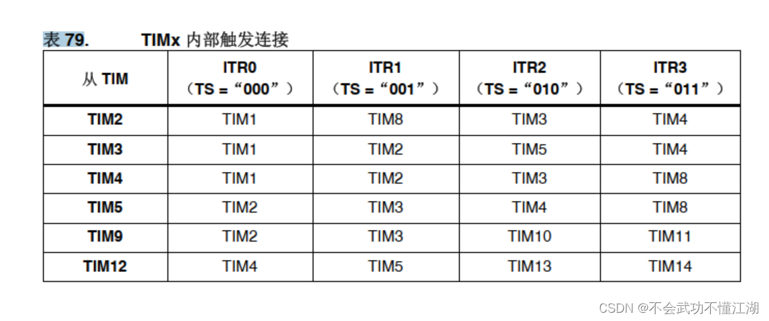

This table is from STM32F4XX Chinese Reference Manual
Program :
stepmotor.h
#ifndef __stepmotor_H
#define __stepmotor_H

#include "main.h"

void STEP_MOTOR_PWM_Configuration(u16 arr,u16 pre);// Master timer

void TIM3_Config(u32 PulseNum_B );// From the timer

void PWM_Output_B(u32 PulseNum_B,u8 DIR);

void TIM3_IRQHandler(void);// Interrupt from timer
#endif
# include "stepmotor.h"

//  Master timer TIM2, From the timer TIM3 ,ITR1.

void STEP_MOTOR_PWM_Configuration(u16 arr,u16 pre) // Main timer setting
{

	GPIO_InitTypeDef GPIO_InitStructure;
	TIM_TimeBaseInitTypeDef	TIM_TimeBaseStructure;
	TIM_OCInitTypeDef TIM_OCInitStructure;
// TIM_BDTRInitTypeDef TIM_BDTRInitStructure;

	RCC_AHB1PeriphClockCmd(RCC_AHB1Periph_GPIOA | RCC_AHB1Periph_GPIOB | RCC_AHB1Periph_GPIOC | RCC_AHB1Periph_GPIOE, ENABLE);
  RCC_APB1PeriphClockCmd(RCC_APB1Periph_TIM2, ENABLE);

	GPIO_PinAFConfig(GPIOA,GPIO_PinSource3,GPIO_AF_TIM2); //


	// PWM PA3
	GPIO_InitStructure.GPIO_Pin =  GPIO_Pin_3;		 //
	GPIO_InitStructure.GPIO_Speed = GPIO_Speed_100MHz;
  GPIO_InitStructure.GPIO_Mode = GPIO_Mode_AF;
	GPIO_InitStructure.GPIO_OType = GPIO_OType_PP; // Multiplexing push pull output
	GPIO_InitStructure.GPIO_PuPd = GPIO_PuPd_UP; // Pull up
	GPIO_Init(GPIOA,&GPIO_InitStructure); // initialization  PB14
	TIM_TimeBaseStructure.TIM_Period= arr-1;
	TIM_TimeBaseStructure.TIM_Prescaler= pre-1;
	TIM_TimeBaseStructure.TIM_CounterMode=TIM_CounterMode_Up;
	TIM_TimeBaseStructure.TIM_ClockDivision=TIM_CKD_DIV1;
	TIM_TimeBaseStructure.TIM_RepetitionCounter = 0;
	TIM_TimeBaseInit(TIM2,&TIM_TimeBaseStructure);	 //TIM2

	TIM_OCInitStructure.TIM_OCMode = TIM_OCMode_PWM1;
	TIM_OCInitStructure.TIM_OutputState = TIM_OutputState_Enable;
	TIM_OCInitStructure.TIM_Pulse = arr/2;
	TIM_OCInitStructure.TIM_OCPolarity = TIM_OCPolarity_High;

	TIM_OC4Init(TIM2, &TIM_OCInitStructure);

	TIM_SelectMasterSlaveMode( TIM2, TIM_MasterSlaveMode_Enable);		//  Timer master-slave mode enable
	TIM_SelectOutputTrigger( TIM2, TIM_TRGOSource_Update);

	TIM_OC4PreloadConfig(TIM2, TIM_OCPreload_Enable);

	TIM_ARRPreloadConfig(TIM2,ENABLE);

void TIM3_Config(u32 PulseNum_B )// Set from the timer
{

	TIM_TimeBaseInitTypeDef	TIM_TimeBaseStructure;
	NVIC_InitTypeDef	NVIC_InitStructure;

	RCC_APB1PeriphClockCmd( RCC_APB1Periph_TIM3, ENABLE);

	TIM_TimeBaseStructure.TIM_Period = PulseNum_B;
	TIM_TimeBaseStructure.TIM_Prescaler = 0;
	TIM_TimeBaseStructure.TIM_ClockDivision = TIM_CKD_DIV1;
	TIM_TimeBaseStructure.TIM_CounterMode = TIM_CounterMode_Up;
	TIM_TimeBaseInit( TIM3, &TIM_TimeBaseStructure);


	TIM_SelectInputTrigger( TIM3, TIM_TS_ITR1);			// TIM2- Lord ,TIM3- from
	TIM_SelectSlaveMode( TIM3, TIM_SlaveMode_Gated);
	TIM_ITConfig( TIM3, TIM_IT_Update, ENABLE);

	NVIC_PriorityGroupConfig(NVIC_PriorityGroup_3);
	NVIC_InitStructure.NVIC_IRQChannel = TIM3_IRQn;
	NVIC_InitStructure.NVIC_IRQChannelPreemptionPriority = 2;
	NVIC_InitStructure.NVIC_IRQChannelSubPriority = 3;
	NVIC_InitStructure.NVIC_IRQChannelCmd = ENABLE;
	NVIC_Init( &NVIC_InitStructure);
}
void PWM_Output_B( u32 PulseNum_B,u8 DIR)			// TIM2- Lord ,TIM3- from
{

	if(DIR == 0)
			GPIO_SetBits(GPIOC, GPIO_Pin_4);// C4--DIR
	else
			GPIO_ResetBits(GPIOC, GPIO_Pin_4);// C4--DIR


	TIM3_Config(PulseNum_B);
	TIM_Cmd( TIM3, ENABLE);
	TIM_ClearITPendingBit( TIM3, TIM_IT_Update);
	TIM_ITConfig( TIM3, TIM_IT_Update, ENABLE);
	STEP_MOTOR_PWM_Configuration( 1000,84);		//F429: The general timer is  84MHz,  so 84MHz / 84 = 1MHz
	TIM_Cmd( TIM2, ENABLE);
	void TIM3_IRQHandler(void)
{

	if (TIM_GetITStatus( TIM3, TIM_IT_Update) != RESET)
	{

		TIM_ClearITPendingBit( TIM3, TIM_IT_Update);			//  Clears the interrupt flag bit
		TIM_Cmd( TIM2, DISABLE);			//  off timer 2
		TIM_Cmd( TIM3, DISABLE);			//  off timer 3
		TIM_ITConfig( TIM3, TIM_IT_Update, DISABLE);
	}
}
}
main.c
#include "stm32f4xx.h"
#include "usart.h"
#include "delay.h"
#include "main.h"

float motor_t;

int main(void)
{

 	 SystemInit();
	start_up();
	NVIC_PriorityGroupConfig(NVIC_PriorityGroup_3);
	TIM7_Init(TIM7_ARR,TIM7_PRE); /*  Master clock initialization  */
  	usart2_Config(100000);
	Can_Init();
	PID_Init();
  	LED_Init();
	PWM_Configuration(40,84);// 50kHz=20 , 25KHz=40 // DC brushless motor
	ENCODER_Configuration(12800); // Encoder

	PWM_Output_B(10000,0); // Stepper motor  DIR:0- positive ,1- reverse ,


	while(1)
	{

		LOOP();

	}

}
Call once in the initialization program PWM_Output_B() that will do .
边栏推荐
- [ffmpeg] [reprint] image mosaic: picture in picture with wheat
- QDataStream的简单读写验证
- Numeric amount plus comma; JS two methods of adding three digits and a comma to numbers; JS data formatting
- Rainbow combines neuvector to practice container safety management
- Use and principle of wait notify
- Global and Chinese markets for soft ferrite cores 2022-2028: Research Report on technology, participants, trends, market size and share
- Use and principle of Park unpark
- Global and Chinese market of paper machine systems 2022-2028: Research Report on technology, participants, trends, market size and share
- Set set detailed explanation
- Things generated by busybox
猜你喜欢

Actual combat: gateway api-2022.2.13
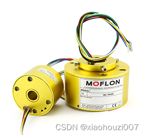
Precautions for use of conductive slip ring

Use of STM32 expansion board temperature sensor and temperature humidity sensor
![Fiber Bragg grating (FBG) notes [1]: waveguide structure and Bragg wavelength derivation](/img/83/97c0c6e23cbb7b4c2b630c217c5206.jpg)
Fiber Bragg grating (FBG) notes [1]: waveguide structure and Bragg wavelength derivation

tar命令

Thread process foundation of JUC

使用 Nocalhost 开发 Rainbond 上的微服务应用
Rainbond结合NeuVector实践容器安全管理

Mathematical knowledge: finding the number of divisors

How to meet the requirements of source code confidentiality and source code security management
随机推荐
Printk debugging summary
液压滑环的特点讲解
QT waiting box production
C# wpf 使用DockPanel实现截屏框
Spanner 论文小结
Use and principle of reentrantlock
How to traverse massive data in redis
[SRS] use of Vhost isolated stream: push / pull Stream Address
Global and Chinese markets of gps/gnss receiver modules 2022-2028: Research Report on technology, participants, trends, market size and share
LevelDB源码分析之LRU Cache
担心侵权?必备无版权素材网站分享,不用担心视频剪辑缺素材
Web Security (IX) what is JWT?
3D建模與處理軟件簡介 劉利剛 中國科技大學
Redis database deployment and common commands
Global and Chinese market of digital badge 2022-2028: Research Report on technology, participants, trends, market size and share
Global and Chinese market of metal oxide semiconductor field effect transistors 2022-2028: Research Report on technology, participants, trends, market size and share
Rust hello-word
Memtable for leveldb source code analysis
Global and Chinese markets for business weather forecasting 2022-2028: Research Report on technology, participants, trends, market size and share
Rust基础入门之变量绑定与解构