当前位置:网站首页>Overview of camera image quality
Overview of camera image quality
2022-06-12 06:07:00 【A maverick zhu】
Preface :
For many newcomers camera tuning My little friend said , Maybe I don't know much about image quality , Even when I first came into this field, it was the same , Unclear ISP What is it? , Why should I adjust it , What are the factors that affect the image quality , Which are ISP Adjustable , What can't be adjusted , So this article mainly introduces the concept of image quality , From the image quality introduction 、 Introduction to imaging system 、 Examples of typical factors affecting image quality , Three pieces of content , I hope it will be helpful to my new friends , Can deepen the understanding of image quality ;
Catalog
1、 Introduction to image quality
1-1、 Classification of imaging products
1-2、 Image quality classification
1-3、 Image quality requirements for imaging products
2、 Introduction to imaging system
2-1、 Composition of imaging system
2-2、 Two main lines of imaging system
2-3、 Real time control of imaging system
3、 Examples of typical factors affecting image quality
3-1、 Optics and lenses 、IR Related image quality problems
3-2、CMOS Sensor Related image quality problems
3-3、ISP Related image quality problems
3-4、Encoder Related image quality problems
3-5、 Display related image quality problems
1、 Introduction to image quality
1-1、 Classification of imaging products

1-2、 Image quality classification
Aesthetic ( The human eye judges )
no artefacts ! color,noise,detail,focus speed、etc
Informative ( Machine identification 、 testing )
fast,no information lost,visibility,certain level tolerace to artefacts、etc
Classification of imaging products according to image quality requirements

1-3、 Image quality requirements for imaging products
Image quality requirements for aesthetic imaging products
SLR camera -- The real world , Certain objective imaging standards should be followed CIPA,ISO, If there is a need for artistic creation, you can use PS And so on ;
Mobile camera -- Favors human vision , in personam / There are certain requirements for face shooting ;
Unmanned aerial vehicle (uav) / Motion camera -- Video stability ( Shake proof 、 It is not allowed to change the picture ), in personam / There are certain requirements for face shooting ;
Surveillance cameras -- Low illumination noise ( Time domain , airspace )、HDR、 High sharpness 、 in personam / There are certain requirements for face shooting ;
Image quality requirements for information imaging products
Machine vision camera -- people / Face 、 High sensitivity ;
Home Camera -- Home camera , Similar to a surveillance camera , There are certain requirements for face recognition ;
Car camera -- High dynamic range 、 High sensitivity 、 hfr 、motion artefacts、stitching artifacts、 Meet certain human vision ( Forward looking / The rear view camera is seen by the human eye );
2、 Introduction to imaging system
2-1、 Composition of imaging system

To understand image quality , It is necessary to understand the composition of the whole imaging system , Find out which modules in the whole imaging system will affect the image quality , The imaging process is described above , The light source ( Contains artificial light 、 Natural light 、 The flash ) Shine on an object , Light is reflected into the imaging system , Pass the camera ( For the zoom lens, there is a driving motor to adjust the lens position , Zoom )、 aperture 、 Filter 、 Shutter reaches Sensor Imaging on , Then the digital signal is sent to ISP Image processing ,ISP Output YUV Formatted data , Used for displaying or storing after coding , Or for machine vision ; So there are many factors that affect image quality , Including light source 、 The lens 、 Filter 、Sensor、ISP、 The display on the monitor 、 code ........
Understand that it is the light source 、 The lens 、 aperture 、 Filter 、 Shutter 、Sensor It constitutes a complete optical imaging system , However, the defects and limitations of Optics and semiconductors will lead to a series of imaging problems , You need to go through ISP, Using digital signal processing method to overcome optical , Imaging problems caused by defects in semiconductors , After processing and getting a better image , It is used to display images 、 Storage 、 Or the detection and recognition of machine vision ;
summary : The whole imaging system is a combination of hardware and software 、 The complex system of optical electromechanical combination , Do some system architecture and hardware architecture , It is necessary to understand the whole system , To design the right Architecture , Including image quality, it also deals with problems from a system perspective , Also understand the whole system , In order to better complete the work ;
2-2、 Two main lines of imaging system
Image reconstruction --- Draw the right scene clearly ( The process of image reconstruction , Is to use digital signal processing methods to overcome optical 、 Defects in semiconductors , Draw the right scene clearly )
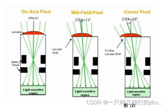
Optical defects and limitations : MTF、 Aberrations 、 A song 、vignetting( Halo , Dark angle )/luma shading( Brightness shadow )、glare( glare )、Geometry Distortion( Geometric distortion )
Semiconductor defects and limitations :defect pixel、sensitivity、dynamic range、noise:temperal noise、fix pattern noise、color noise、spatial noise
Color reconstruction --- Restore accurate and rich colors ( Sometimes it must conform to people's subjective tendency )
Optical defects and limitations :Color shading、chromatic aberration、purple fringe
Semiconductor defects and limitations :Cross talk、balck level
2-3、 Real time control of imaging system
Generally, the same products are obtained from hardware manufacturers , The imaging effect is almost the same , Therefore, to have a better user experience, we must add our own optimization to the software , Such as 3A Algorithm 、 Post processing algorithm ;
Static parameters of the system :black level、shading、noise profile、white balance、chromatic aberration correction
AE\AWB\AF( Auto exposure 、 Automatic white balance 、 Autofocus ): Reach exposure / white balance / Focused “ fast ”、“ accurate ”、“ steady ”
Dynamic parameters of the system :shading,CCM, black level,noise reduction,sharpening
3、 Examples of typical factors affecting image quality
3-1、 Optics and lenses 、IR Related image quality problems
- distortion


- luma shading


- color shading


- glare 、 Ghost


- Purple edge


3-2、CMOS Sensor Related image quality problems
- Bad point

- noise (Fix pattern noise 、 Thermal noise )
- sensor filp/mirror
3-3、ISP Related image quality problems
- Sports drag


3-4、Encoder Related image quality problems
- mosaic
- ringing ( Jingling )

- contouring

- blurry( Fuzzy )

- mosquito ( Mosquito noise )

3-5、 Display related image quality problems
- The TV PQ( Picture-Quality) It can lead to Camera The display effect is inconsistent ( brightness 、 color 、 Noise, etc );
- Display color gamut 、 Differences in color levels can lead to Camera The display effect is inconsistent ;


边栏推荐
- Unity C script implements AES encryption and decryption
- Liunx Foundation
- How to increase heap size of JVM [duplicate] - how to increase heap size of JVM [duplicate]
- A month's worth of DDD will help you master it
- [PowerShell] command line output and adding system environment variables
- sqlite交叉編譯動態庫
- Guns framework multi data source configuration without modifying the configuration file
- Project technical structure
- Script for unity3d to recursively search for a node with a specific name from all child nodes of a node
- MNIST handwritten data recognition by CNN
猜你喜欢

Pytorch implementation of regression model

n次贝塞尔曲线

勤于奋寻找联盟程序方法介绍

Project and build Publishing

The application could not be installed: INSTALL_ FAILED_ TEST_ ONLY

First note

Es6-es11 learning
![[PowerShell] command line output and adding system environment variables](/img/49/b92175181aa4a3fddfa3adcacf1d72.jpg)
[PowerShell] command line output and adding system environment variables

Leetcode-1706. Where does the club fall

Directx11 advanced tutorial PBR (1) summary of physical phenomena of light
随机推荐
Leetcode-646. Longest number pair chain
数据库为什么不使用hash表?
nRF52832自定義服務與特性
(UE4 4.27) UE4 adds a customized meshpass to realize the edge illumination of the mobile terminal
sqlite交叉編譯動態庫
Leetcode simple problem: converting an integer to the sum of two zero free integers
China embolic coil market trend report, technical innovation and market forecast
cv2.fillPoly coco annotator segment坐标转化为mask图像
夜神模拟器adb查看log
. Net core and Net framework comparison
Unity3d multi platform method for reading text files in streamingasset directory
[PowerShell] command line output and adding system environment variables
Project progress on February 28, 2022
哈工大信息内容安全实验
Why is the union index the leftmost matching principle?
Login authentication filter
JS变量作用域
EBook editing and deleting
交叉编译libev
MNIST handwritten data recognition by CNN