当前位置:网站首页>7905 and TL431 negative voltage regulator circuit - regulator and floating circuit relative to the positive pole of the power supply
7905 and TL431 negative voltage regulator circuit - regulator and floating circuit relative to the positive pole of the power supply
2022-06-11 19:57:00 【Carranza】
Negative voltage : Take the positive pole of the power supply as the reference zero point
First, clarify , The so-called negative voltage stabilization here does not generate a negative voltage like a charge pump , It's like 7905 The role of , The ground and input of the voltage stabilizing chip / The output voltage is reversed ,GND Higher voltage . If GND Connect the positive pole of the power supply , The output is a constant voltage lower than the power supply , If the positive pole of the power supply is taken as the reference zero potential , The regulator outputs a negative voltage . In fact, it's just like PNP The data of triode are all negative , Here's the picture :

So common 1117 And so on. LDO Is it possible to reverse the voltage stabilization by reverse connection ? You can try [ dog's head ]
In many places 7905 Is and 7805 Used in a symmetrical combination , Similar to the following :
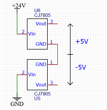
In this way, the following circuits only need to connect their ground to 7805 and 7905 Middle ground pin , The positive and negative two-way stable voltage can be obtained , It is simple and convenient to provide dual power supply for operational amplifier .
If zener diode is used
The voltage regulator can replace the voltage regulator to realize the stable voltage relative to the negative pole of the power supply , Just not so stable , Output capacity is also urgent , But the advantage is that the same regulator can achieve negative voltage regulation by changing its position :
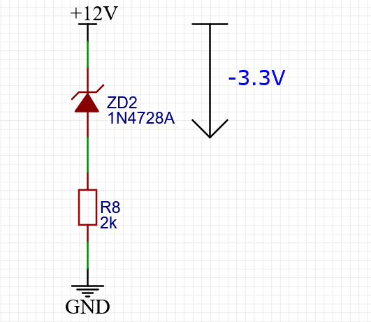
After all, the principle of the regulator is , When the voltage at both ends of the regulator rises above the threshold, the current passing through the regulator will increase , A resistor in series can use this current to produce a greater voltage drop , Stabilize the voltage at both ends of the voltage stabilizer . The resistor can be placed in front , Of course, it can also be put in the back .
use TL431
TL431 On the circuit diagram, it looks like a regulator tube , The effect is similar , When the voltage exceeds the threshold, increase the current passing through both ends . Therefore, the regulator tube in the above figure can be directly replaced with TL431.

It is slightly different from the real zener diode ,TL431 One more pin , It's the one on the right side of the picture . It's not complicated , This is a TL431 The reference pin of , It can also be said to be a voltage detection pin , When the voltage of this pin relative to the anode exceeds 2.5V when , after TL431 The current of becomes larger , Then there is the same principle as the ordinary regulator . The anode is usually used for grounding .
In the figure, the reference pin is connected with the cathode , That is to say, receiving +12V, So as long as TL431 The voltage at the other end is lower than 9.5V, The voltage across it exceeds 2.5V, The current gets bigger ,R15 The voltage on the rises ,TL431 The voltage at both ends decreases again .
This circuit is bought casually on a treasure TL431 tested , Power supply voltage from 2.5V To 30V, Regulated value from -2.5V Change to -2.53V, It's stable enough , Just below 2k The resistance started to give off a wonderful smell in the middle [ dog's head ].
It can also be like ordinary TL431 The circuit uses the voltage divider to achieve adjustable voltage stabilization , such as :
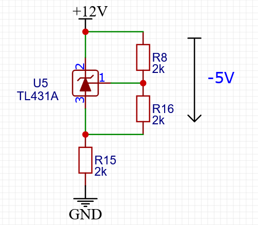
Like I said before , because TL431 Voltage stabilizing effect of , The voltage of the detection pin relative to the anode is 2.5V, That is to say R16 The voltage at both ends is 2.5V, So after R16 The current of is :
I R = 2.5 R 16 I_R = \frac{2.5}{R_{16}} IR=R162.5
Ohm's law , Easy to use at any time . Ignore inflow or outflow TL431 Detect the current of the pin , Because it is very small , So after R8 The current of is equal to R16 The current on the is the same ,R8 The voltage at both ends is :
V R 8 = I R ∗ R 8 V_{R_8} = I_R * R_8 VR8=IR∗R8
TL431 The voltage from cathode to anode is equal to R8 Voltage plus R16 The voltage of , So combine the above two formulas , The stabilized voltage is equal to :
V = 2.5 ⋅ R 8 R 16 + 2.5 V = 2.5 \cdot \frac{R_8}{R_{16}} + 2.5 V=2.5⋅R16R8+2.5
R8 and R16 According to the values in the figure , All are 2k, So the result is :
V = 2.5 ⋅ R 8 R 16 + 2.5 = 2.5 × 1 + 2.5 = 5 V = 2.5 \cdot \frac{R_8}{R_{16}} + 2.5 = 2.5 \times 1 + 2.5 = 5 V=2.5⋅R16R8+2.5=2.5×1+2.5=5
When the positive pole of the power supply is used as a reference, it is -5V.
By the way , The assumption in the above calculation is : Because of inflow or outflow TL431 The current of the detection pin is very small , So you can ignore . This “ Very small ” Is relative to the current across the two resistors , If the value of two voltage dividing resistors is too large , The total amount of current passing through them is very small , that TL431 The shunt current may not be negligible , And this current and TL431 The internal characteristics of , It's not stable .
Another use : Raise the high potential
Negative voltage stabilization can provide negative power supply for operational amplifier , There is another important use . for instance , If the maximum input voltage of a chip in your hand is only 5V, Now I'm going to use it to measure the lowest 9V, The highest 12V The voltage of , The supply voltage is also 12V, What to do ?
The simplest intuitive method is, of course, to start with LDO Step down the power supply to the chip , And a voltage divider , hold 9~12V The input signal of is reduced to 5V within , That is the feeling of touri :

But notice that the amplitude of the signal change is only 3V, That is, relative to +12V, The minimum value of the signal is -3V, So if you give the chip -5V Power supply , The signal range is within the bearing range of the chip , Here's the picture :

This kind of circuit is mostly used for operational amplifier or comparator to measure differential signal , go by the name of “ Floating ground ”. First , Generally, the operating current of operational amplifier or comparator is very small ,R15 The voltage fluctuation on the is not too large , Even a pile of resistors is enough to provide working current for the chip . secondly , The input is a differential signal , And the grounding resistance R15 The interference on the will be added to both input signals at the same time . That is to say, if R15 The voltage rises , That is to say, the ground potential of the chip rises , The input signal is correspondingly reduced , But the difference between the two signals does not change , And this difference is what the chip really cares about . in other words R15 Common mode interference is introduced , It is easier to filter out when measuring differential signals .
conversely , If you use a voltage divider to process the signal first as shown in the first figure , So the differential signal is two signal sources , There must be two sets of voltage dividing circuits, one connected to the other , In this way, the interference introduced by one or two sets of voltage dividing circuits will be superimposed on the two signals independently , The amount and polarity of interference are random , It's hard to deal with .
边栏推荐
- LNMP架构源码编译安装图文讲解(附带搭建论坛实验)
- 周鸿祎:想做直播带货抹不下面子 数据勒索成突出的安全威胁
- Leetcode 1992. Find all farm groups (yes, once)
- 30讲 线性代数第二讲 矩阵
- Unified exception handling
- JMeter installation
- Questions and requirements of marketing course design in autumn 21 of Dagong [standard answer]
- Skywalking source code analysis Part 5 - server configuration configuration module startup
- Implementation of SQL online editor based on Vue + codemirror
- Poj1028 web navigation
猜你喜欢

3D建模有什么技巧吗?

激活函数公式、导数、图像笔记

"Video version Mae" of hekaiming team, efficient video pre training! The effect is also very good when mask ratio is up to 90
无监督图像分类《SCAN:Learning to Classify Images without》代码分析笔记(1):simclr

Lecture 30 linear algebra Lecture 2 Matrix
7905 和TL431 负电压稳压电路 - 相对于电源正极的稳压和浮地电路

Tensorflow---TFRecord文件的创建与读取

RTL仲裁器设计
![[Lao Wang's fallacy of brain science] Why do blind people](/img/7c/98f27bb55a1a3b74c0ed8fd7fd2cc5.jpg)
[Lao Wang's fallacy of brain science] Why do blind people "seem" to be more "sensitive" than normal people?
Google proposed the super pre training model coca, and the accuracy of fine-tuning top-1 on Imagenet reached 91%! SOTA! On multiple downstream tasks
随机推荐
YOLOv3 Pytorch代码及原理分析(二):网络结构和 Loss 计算
POJ 1458 longest common subsequence (dynamic planning exercise)
Anaconda installation, jupyter notebook default startup path modification and nbextensions plug-in installation
Detailed explanation on persistence of 2022redis7.0x
【高精度】X进制整数加法
In 2021, the global revenue of flexible fireproof sealant is about 755.2 million dollars, and it is expected to reach 1211.7 million dollars in 2028
[Lao Wang's fallacy of brain science] Why do blind people "seem" to be more "sensitive" than normal people?
2022年最新宁夏建筑八大员(标准员)考试试题及答案
In 2021, the global adult diaper revenue was about $11560million, which is expected to reach $15440million in 2028. From 2022 to 2028, the CAGR was 4.2%
vs2010链接sql2008数据库时无法打开
里氏替换原则
Questions and requirements of the "high rise building structure" assignment of Dayong in the 21st autumn [standard answer]
STL容器嵌套容器
【 aide 】 comment puis - je faire en sorte que les messages sélectionnés ci - dessous puissent être affichés après l'ouverture de l'article Wechat public number dans un navigateur externe?
无监督图像分类《SCAN:Learning to Classify Images without》代码分析笔记(1):simclr
Implementation of SQL online editor based on Vue + codemirror
Activate function formulas, derivatives, image notes
Show your creativity and win the graphics card! Mmpose attitude estimation creative contest shocks
The first bullet of comparative learning
Flutter doctor 显示xcode没有安装的解决办法