当前位置:网站首页>Simplest DIY mpu6050 gyroscope attitude control actuator program based on stm32f407 Explorer development board
Simplest DIY mpu6050 gyroscope attitude control actuator program based on stm32f407 Explorer development board
2022-06-23 10:40:00 【daodanjishui】
STM32 Library function development series article directory
Chapter one :STM32F103ZET6 Program design and implementation of dual serial port mutual transmission of single chip microcomputer
Second articles : The most simple DIY be based on STM32 Design scheme of Bluetooth intelligent car based on single chip microcomputer
Third articles : The most simple DIY be based on STM32F407 Explorer development board MPU6050 Gyro attitude control steering gear program
List of articles
Preface
daodanjishui The simplest of the core original technologies of the Internet of things DIY be based on STM32F407 Explorer development board MPU6050 Gyro attitude control steering gear program .
There are all kinds of open source on the market STM32 Steering gear controller , But there are complex and simple , If you want to get started stm32f407zgt6 Actuator control of attitude sensor , This plan will give you a quick and efficient plan .
One 、 The most simple DIY be based on STM32F407 Explorer development board MPU6050 What is the procedure of gyro attitude control actuator ?
I remember in “51 SCM intelligent small design ” The column tells about 51 How does a single chip microcomputer excite through a register PWM Wave control sg90 Steering gear blog . But because of 51 SCM resources are limited , Plus the complex attitude solution , It is very difficult to complete the task of controlling the steering gear by attitude calculation at the same time , So this blog was born .
The plan this time is mainly : Based on the punctual atom STM32F407 Explorer development board and MPU6050 Gyroscope to collect heading angle to use IO The port directly controls the turning of a steering gear . Now please look at the family photo :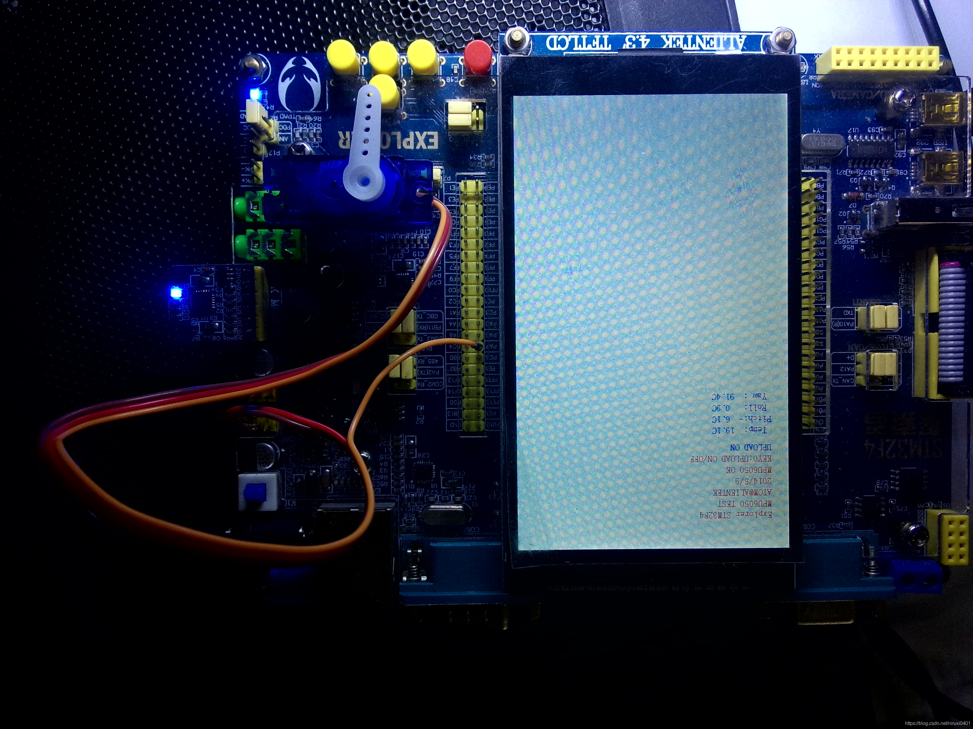

This program uses stm32 Library functions to program , To be honest, I also modified the routines supporting the punctual atomic development board , The punctual atom transplant arduino Version of IIC control MPU6050 My library has my following , To achieve this STM32 Steering gear control , I consulted a lot of information and videos about steering gear control on the Internet , I almost swept all the forum posts about steering gear control of punctual atoms , There are not many posts with gold content , Given the source code of the program, I think there is more or less a problem , I stepped on a lot of pits ! Some people will say :“daodanjishui Why are you so persistent ? A lot of arduino Library for you to use to control the steering gear , control MPU6050, But you insist on starting from the bottom to control the steering gear !” I said, :“ A qualified software and hardware design engineer should at least break through the bottom , To really control the hardware smoothly . Do this , How difficult is it to control a manipulator casually ? Why is it difficult to write another upper computer to control the steering gear ? Write a mobile phone to control the steering gear APP Why is it difficult ? If you have been debugging with an anonymous four-axis host computer MPU6050, Can you write your own upper computer ? People are not open source at present , Can you still write such an upper computer ? ha-ha ”. up to now , I did write an upper computer controlled by the steering gear : The most simple DIY be based on C# and 51 The single chip microcomputer integrates the upper and lower computers PCA9685 Steering gear control program , In short, writing code is painful , In this era of fast food, the best way is to copy and paste “ si ”, But not everything can be taken , Sometimes when I try, I find that there is nothing to take , You can only harden your scalp and roll up your sleeves to do it .
Youku video demo address :https://v.youku.com/v_show/id_XNTAxMDg2NzE0OA==.html
Watch directly
The most simple DIY be based on STM32F407 Explorer development board MPU6050 Gyro attitude control steering gear program
Two 、 Use steps
1. Prepare the hardware
1.1 On time atomic Explorer development board , If not, use STM32F407ZGT6 The core board is OK , Now America ST The company banned the chip , It is estimated that this chip will be eliminated in the future .
1.2 The steering gear sg90 One .
1.3MPU6050 Module one .
1.4 The punctual atoms 4.3 One inch capacitive display screen .( If not, you can mask this part of the code )
2. Prepare the atomic open source on time MPU6050 Code for
I use library functions to develop , Therefore, the code directly uses the free and open source source source of the development board for secondary development . Source : Explorer CD-ROM data \A disc \4, Program source code \2, Standard routine - Library function version \ experiment 32 MPU6050 Six axis sensor experiment
The code is as follows ( Example ):
#include "sys.h"
#include "delay.h"
#include "usart.h"
#include "led.h"
#include "key.h"
#include "lcd.h"
#include "mpu6050.h"
#include "inv_mpu.h"
#include "inv_mpu_dmp_motion_driver.h"

//ALIENTEK  explorer STM32F407 Development board   experiment 32
//MPU6050 Six axis sensors   experiment  - Library function version
// Technical support :www.openedv.com
// Taobao shop :http://eboard.taobao.com
// Guangzhou Xingyi Electronic Technology Co., Ltd
// author : The punctual atoms  @ALIENTEK

// A serial port 1 send out 1 Characters
//c: The character to send
void usart1_send_char(u8 c)
{


	while(USART_GetFlagStatus(USART1,USART_FLAG_TC)==RESET);
    USART_SendData(USART1,c);

}
// Send data to anonymous four axis host computer software (V2.6 edition )
//fun: Function words . 0XA0~0XAF
//data: Data cache , most 28 byte !!
//len:data Number of valid data in the area
void usart1_niming_report(u8 fun,u8*data,u8 len)
{

	u8 send_buf[32];
	u8 i;
	if(len>28)return;	// most 28 Bytes of data
	send_buf[len+3]=0;	// Set the checksum to zero
	send_buf[0]=0X88;	// Frame head
	send_buf[1]=fun;	// Function words
	send_buf[2]=len;	// Data length
	for(i=0;i<len;i++)send_buf[3+i]=data[i];			// Copy the data
	for(i=0;i<len+3;i++)send_buf[len+3]+=send_buf[i];	// Calculate the check sum
	for(i=0;i<len+4;i++)usart1_send_char(send_buf[i]);	// Send data to serial port 1
}
// Send acceleration sensor data and gyroscope data
//aacx,aacy,aacz:x,y,z Acceleration in three directions
//gyrox,gyroy,gyroz:x,y,z Gyroscope values in three directions
void mpu6050_send_data(short aacx,short aacy,short aacz,short gyrox,short gyroy,short gyroz)
{

	u8 tbuf[12];
	tbuf[0]=(aacx>>8)&0XFF;
	tbuf[1]=aacx&0XFF;
	tbuf[2]=(aacy>>8)&0XFF;
	tbuf[3]=aacy&0XFF;
	tbuf[4]=(aacz>>8)&0XFF;
	tbuf[5]=aacz&0XFF;
	tbuf[6]=(gyrox>>8)&0XFF;
	tbuf[7]=gyrox&0XFF;
	tbuf[8]=(gyroy>>8)&0XFF;
	tbuf[9]=gyroy&0XFF;
	tbuf[10]=(gyroz>>8)&0XFF;
	tbuf[11]=gyroz&0XFF;
	usart1_niming_report(0XA1,tbuf,12);// Custom frame ,0XA1
}
// Through serial port 1 Report the attitude data after settlement to the computer
//aacx,aacy,aacz:x,y,z Acceleration in three directions
//gyrox,gyroy,gyroz:x,y,z Gyroscope values in three directions
//roll: Roll angle . Company 0.01 degree . -18000 -> 18000  Corresponding  -180.00 -> 180.00 degree
//pitch: Pitch angle . Company  0.01 degree .-9000 - 9000  Corresponding  -90.00 -> 90.00  degree
//yaw: Heading angle . Unit is 0.1 degree  0 -> 3600  Corresponding  0 -> 360.0 degree
void usart1_report_imu(short aacx,short aacy,short aacz,short gyrox,short gyroy,short gyroz,short roll,short pitch,short yaw)
{

	u8 tbuf[28];
	u8 i;
	for(i=0;i<28;i++)tbuf[i]=0;// clear 0
	tbuf[0]=(aacx>>8)&0XFF;
	tbuf[1]=aacx&0XFF;
	tbuf[2]=(aacy>>8)&0XFF;
	tbuf[3]=aacy&0XFF;
	tbuf[4]=(aacz>>8)&0XFF;
	tbuf[5]=aacz&0XFF;
	tbuf[6]=(gyrox>>8)&0XFF;
	tbuf[7]=gyrox&0XFF;
	tbuf[8]=(gyroy>>8)&0XFF;
	tbuf[9]=gyroy&0XFF;
	tbuf[10]=(gyroz>>8)&0XFF;
	tbuf[11]=gyroz&0XFF;
	tbuf[18]=(roll>>8)&0XFF;
	tbuf[19]=roll&0XFF;
	tbuf[20]=(pitch>>8)&0XFF;
	tbuf[21]=pitch&0XFF;
	tbuf[22]=(yaw>>8)&0XFF;
	tbuf[23]=yaw&0XFF;
	usart1_niming_report(0XAF,tbuf,28);// Flight control display frame ,0XAF
}

int main(void)
{

	u8 t=0,report=1;			// Reporting is enabled by default
	u8 key;
	float pitch,roll,yaw; 		// Euler Angle
	short aacx,aacy,aacz;		// Acceleration sensor raw data
	short gyrox,gyroy,gyroz;	// Gyroscope raw data
	short temp;					// temperature
	NVIC_PriorityGroupConfig(NVIC_PriorityGroup_2);// Set system interrupt priority group 2
	delay_init(168);  // Initialization delay function
	uart_init(500000);		// Initialize the serial port baud rate to 500000
	LED_Init();					// initialization LED
	KEY_Init();					// Initialization key
 	LCD_Init();					//LCD initialization
	MPU_Init();					// initialization MPU6050
 	POINT_COLOR=RED;// Set the font to red
	LCD_ShowString(30,50,200,16,16,"Explorer STM32F4");
	LCD_ShowString(30,70,200,16,16,"MPU6050 TEST");
	LCD_ShowString(30,90,200,16,16,"[email protected]");
	LCD_ShowString(30,110,200,16,16,"2014/5/9");
	while(mpu_dmp_init())
	{

		LCD_ShowString(30,130,200,16,16,"MPU6050 Error");
		delay_ms(200);
		LCD_Fill(30,130,239,130+16,WHITE);
 		delay_ms(200);
	}
	LCD_ShowString(30,130,200,16,16,"MPU6050 OK");
	LCD_ShowString(30,150,200,16,16,"KEY0:UPLOAD ON/OFF");
	POINT_COLOR=BLUE;// Set the font to blue
 	LCD_ShowString(30,170,200,16,16,"UPLOAD ON ");
 	LCD_ShowString(30,200,200,16,16," Temp: . C");
 	LCD_ShowString(30,220,200,16,16,"Pitch: . C");
 	LCD_ShowString(30,240,200,16,16," Roll: . C");
 	LCD_ShowString(30,260,200,16,16," Yaw : . C");
 	while(1)
	{

		key=KEY_Scan(0);
		if(key==KEY0_PRES)
		{

			report=!report;
			if(report)LCD_ShowString(30,170,200,16,16,"UPLOAD ON ");
			else LCD_ShowString(30,170,200,16,16,"UPLOAD OFF");
		}
		if(mpu_dmp_get_data(&pitch,&roll,&yaw)==0)
		{

			temp=MPU_Get_Temperature();	// Get the temperature value
			MPU_Get_Accelerometer(&aacx,&aacy,&aacz);	// Get the acceleration sensor data
			MPU_Get_Gyroscope(&gyrox,&gyroy,&gyroz);	// Get gyro data
			if(report)mpu6050_send_data(aacx,aacy,aacz,gyrox,gyroy,gyroz);// Send acceleration and gyroscope raw data with custom frame
			if(report)usart1_report_imu(aacx,aacy,aacz,gyrox,gyroy,gyroz,(int)(roll*100),(int)(pitch*100),(int)(yaw*10));
			if((t%10)==0)
			{

				if(temp<0)
				{

					LCD_ShowChar(30+48,200,'-',16,0);		// Show minus sign
					temp=-temp;		// Turned positive
				}else LCD_ShowChar(30+48,200,' ',16,0);		// Remove the minus sign
				LCD_ShowNum(30+48+8,200,temp/100,3,16);		// Show integer part
				LCD_ShowNum(30+48+40,200,temp%10,1,16);		// Show decimal part
				temp=pitch*10;
				if(temp<0)
				{

					LCD_ShowChar(30+48,220,'-',16,0);		// Show minus sign
					temp=-temp;		// Turned positive
				}else LCD_ShowChar(30+48,220,' ',16,0);		// Remove the minus sign
				LCD_ShowNum(30+48+8,220,temp/10,3,16);		// Show integer part
				LCD_ShowNum(30+48+40,220,temp%10,1,16);		// Show decimal part
				temp=roll*10;
				if(temp<0)
				{

					LCD_ShowChar(30+48,240,'-',16,0);		// Show minus sign
					temp=-temp;		// Turned positive
				}else LCD_ShowChar(30+48,240,' ',16,0);		// Remove the minus sign
				LCD_ShowNum(30+48+8,240,temp/10,3,16);		// Show integer part
				LCD_ShowNum(30+48+40,240,temp%10,1,16);		// Show decimal part
				temp=yaw*10;
				if(temp<0)
				{

					LCD_ShowChar(30+48,260,'-',16,0);		// Show minus sign
					temp=-temp;		// Turned positive
				}else LCD_ShowChar(30+48,260,' ',16,0);		// Remove the minus sign
				LCD_ShowNum(30+48+8,260,temp/10,3,16);		// Show integer part
				LCD_ShowNum(30+48+40,260,temp%10,1,16);		// Show decimal part
				t=0;
				LED0=!LED0;//LED flashing
			}
		}
		t++;
	}
}
3. Prepare punctual atom PWM The output code
Because controlling the steering gear requires PWM wave , Then we need to use PWM About open source code , The code path is : Explorer CD-ROM data \A disc \4, Program source code \2, Standard routine - Library function version \ experiment 9 PWM Output experiment
#include "sys.h"
#include "delay.h"
#include "usart.h"
#include "led.h"
#include "pwm.h"


//ALIENTEK  explorer STM32F407 Development board   experiment 9
//PWM Output experiment - Library function version
// Technical support :www.openedv.com
// Taobao shop :http://eboard.taobao.com
// Guangzhou Xingyi Electronic Technology Co., Ltd
// author : The punctual atoms  @ALIENTEK

int main(void)
{

	u16 led0pwmval=0;
	u8 dir=1;
	NVIC_PriorityGroupConfig(NVIC_PriorityGroup_2);// Set system interrupt priority group 2
	delay_init(168);  // Initialization delay function
	uart_init(115200);// Initialize the serial port baud rate to 115200
 	TIM14_PWM_Init(500-1,84-1);	//84M/84=1Mhz The counting frequency of , Reload value 500, therefore PWM The frequency is  1M/500=2Khz.
   while(1) // Realize the comparison value from 0-300 Increasing , To 300 From 300-0 Decline , loop
	{

 		delay_ms(10);
		if(dir)led0pwmval++;//dir==1 led0pwmval Increasing
		else led0pwmval--;	//dir==0 led0pwmval Decline
 		if(led0pwmval>300)dir=0;//led0pwmval arrive 300 after , The direction is decreasing
		if(led0pwmval==0)dir=1;	//led0pwmval Descending to 0 after , Change the direction to incremental

		TIM_SetCompare1(TIM14,led0pwmval);	// Modify the comparison value , Change the duty cycle
	}
}
4. Modify the source code and combined source code ( This part is original )
Here are two parts of the original code :
(1) The first part
// Join in PWM Control the steering gear
		//tempp=pitch;// Pitch angle
		    aaaa=yaw;// Heading angle
		    //bbbb=aaaa/2;
		    //led0pwmva2=880+tempp;// The program part of the original author , I don't explain , Because it's not easy to use , You are good at reading .
				//led0pwmval=880+bbbb;// The program part of the original author , I don't explain , Because it's not easy to use

		  // The following logic is to control a steering gear to rotate the corresponding angle according to the rotation amplitude of the heading angle
		// It is also the core code of steering gear control , I won't explain the discount code , I can consider raising the price , Please contact me if you need to pay
		  if((yaw>=0)&&(yaw<=180)){
    // Within the control range of the steering gear ,180 D's steering gear
				led0pwmval=(u16)10*(1755-yaw)/18.0;// Convert heading angle into timer comparison value , If you add yaw Will not produce accurate results , Free code I won't explain the key formula here , There will be explanations for charging
			  TIM_SetCompare1(TIM14,led0pwmval);
			  delay_ms(10);// If this delay is adjusted to 500ms It will cause problems in collecting gyroscope data
		  }
(2) The second part
 // The following test code , Let the steering gear from 0 Go to 180, Back to 0 degree , Keep cycling
		  led0pwmval=975;//0 degree
		TIM_SetCompare1(TIM14,led0pwmval);
		    delay_ms(1000);
		  led0pwmval=950;//45 degree
		TIM_SetCompare1(TIM14,led0pwmval);
		    delay_ms(1000);
		  led0pwmval=925;//90 degree
		TIM_SetCompare1(TIM14,led0pwmval);
		    delay_ms(1000);
		  led0pwmval=900;//135 degree
			TIM_SetCompare1(TIM14,led0pwmval);
		    delay_ms(1000);
		  led0pwmval=875;//180 degree
			TIM_SetCompare1(TIM14,led0pwmval);
		    delay_ms(1000);
explain : The first part is the core algorithm of actuator control , I derived the simplified . The second part is the test program of the steering gear , Test the fixed action of the steering gear . There is no problem for readers to deduce the results from these codes , I also spent a lot of time deliberating . If you really don't want to deliberate , Please download the engineering code in my last appendix .
3、 ... and 、 Operation and debugging
(1) Functional specifications : use MPU6050 The attitude data control the steering gear to turn 0 To 180 degree , It also supports debugging simulation waveform and steering gear state with anonymous four-axis host computer , The buyer can change to multiple steering gear control according to the code .
(2) Code instructions : use MDK5 Write library function code
(3) Hardware description : Need to use the punctual atom Explorer development board , Matching their own 4.3 Inch capacitance screen , Supporting their own home MPU6050 modular , One from another family SG90 The steering gear . If the economic condition is good, the buyer can take the punctual atom family bucket set to test , Basically, there is no need to consider the connection , Just plug it in , Except for the steering gear, the data cable has to be connected by itself . If you want to save money , Then figure out for yourself what is annotated in the program IO The pin definition is wired by itself , At the same time, you should also consider what errors you will encounter if you do not connect the display screen, and check them slowly , Anyway, it's connected to the steering gear IO The mouth is PA7, I am the user of the whole family bucket set , You don't need to think so much about
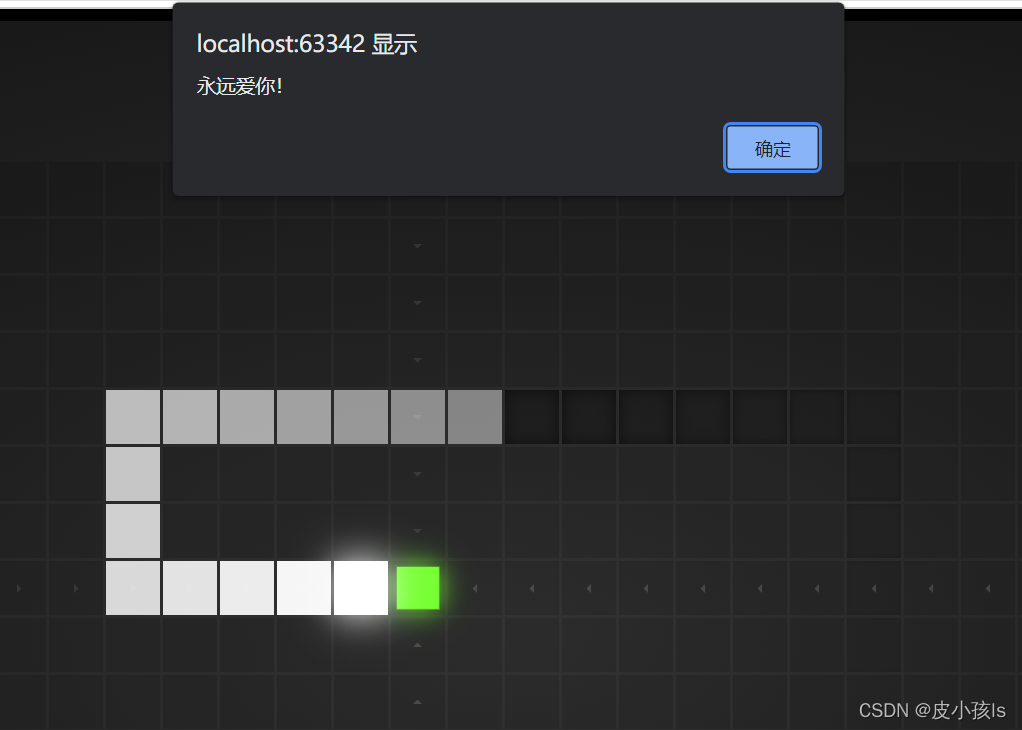
(4) Software specifications : Using the punctual atomic Explorer library function version experiment 32 MPU6050 Six axis sensor experiment The code of , The manual of punctual atom also introduces the basic use method of the program and code notes , In addition, you can use the anonymous four-axis host computer to debug the steering gear . Need to connect serial port , Set the baud rate to 500000( Maximum ). As shown in the figure below :
The simulation shows that : The attitude waveform is shown in the figure below 
Turning angle diagram of steering gear , The change of heading angle is the change of steering gear angle, as shown in the figure below 0 degree 
Turning angle diagram of steering gear , The change of heading angle is the change of steering gear angle, as shown in the figure below 26 degree 
The steering gear turns over 9 The degree is shown in the following figure 
Flip 90 The steering gear of degrees is as follows 
Through the above operation and debugging, it is proved that the program is in good condition , Meet the requirements of the blog .
summary
Some readers say : Why not PCA9685 Control the steering gear ? In fact, I have launched , It's just STM32 Introduction to steering gear control , You can't increase the difficulty all at once .
Extended description : If you get a steering gear , Then you can handle multiple steering engines , It is very efficient to write code with library functions , Unlike the last time I used 51 It is so troublesome to control the steering gear by single chip microcomputer , All are configuration registers and timers . So I call it the simplest steering gear control program , The core code I write is just a few lines , Readers who can understand make a lot of money . What's left is that of a punctual atom MPU6050 Sample code , Readers who don't understand it can see the tutorial document of punctual atom for themselves .
Next up : For next period stm32 control PCA9685 The module indirectly goes to the cluster to control multiple rudders , And the robot arm composed of steering gear is controlled by infrared remote controller , You can't miss it , Worth waiting for .
Finally, attach the download address of this blog post code :https://www.cirmall.com/circuit/22260/
Direct jump
On time atom related code is free to download
边栏推荐
- Five SQL functions for operation date that must be known in SQL tutorial
- Noi OJ 1.3 05: floating point numeric C language for calculating fractions
- 2021-05-11 abstract class
- Google Earth Engine(GEE)——GEDI L2A Vector Canopy Top Height (Ver
- 实现领域驱动设计 - 使用ABP框架 - 通用准则
- 图片存储--引用
- list的深度剖析及模拟实现
- 搭建一个点歌QQ机器人,另外还能看美女
- SPI与IIC异同
- 2021-04-16 array
猜你喜欢
Confessing with Snake games (with source code)

Several practical software sharing

Stockage d'images - référence

Explain in detail the method of judging the size end

Economic common sense

最简单DIY基于蓝牙、51单片机和舵机的钢铁爱国者机关枪控制器

技术创造价值,手把手教你薅羊毛篇

Build the information and innovation industry ecology, and make mobile cloud based on the whole stack of independent innovation

Cool photo album code, happy birthday to the object!
最简单DIY基于STM32F407探索者开发板的MPU6050陀螺仪姿态控制舵机程序
随机推荐
验证码redis实践总结
Noi OJ 1.4 04: odd even ASCII value judgment C language
圖片存儲--引用
为什么poll/select在open时要使用非阻塞NONBLOCK
最简单DIY基于STM32的远程控制电脑系统②(无线遥杆+按键控制)
php反射类使用
What is a good quick development framework like?
实现常用C语言字符串处理函数
What does NFTs, Web3 and metauniverse mean for digital marketing?
Noi OJ 1.3 11: C language for calculating the remainder of the division of floating-point numbers
AI芯片技术-2022年
NOI OJ 1.2 整数数据类型存储空间大小
NOI OJ 1.4 03:奇偶数判断 C语言
Step by step introduction to sqlsugar based development framework (9) -- Realizing field permission control with WinForm control
Noi OJ 1.2 06: round floating point numbers to zero
Install the typescript environment and enable vscode to automatically monitor the compiled TS file as a JS file
MySQL基础-笔记
2021-04-27 classes and objects
Unity technical manual - limit velocity over lifetime sub module and inherit velocity sub module
Analysis of LinkedList source code