当前位置:网站首页>Gd32 ADC acquisition voltage
Gd32 ADC acquisition voltage
2022-06-26 02:44:00 【_ jym】
The chip used is GD32F307
ADC
Continuous conversion mode , It can run on the rule group channel , Once the corresponding software trigger or external trigger is generated ,ADC Will sample and convert the specified channel .
Sampling time , Each channel can be sampled at different times .ADC Use several ADC_CLK Periodically sample the input voltage , stay 12 Bit resolution , Total conversion time = Sampling time +12.5 individual ADCCLK cycle .
The number of sampling periods can be determined by ADC_SAMPT0 and ADC_SAMPT1 The register of SPTn[2:0] Bit change . This is shown below .
If you want to sample faster , Then you can set the sampling time to 1.5 individual ADCCLK cycle .
/* ADC channel sample time */
#define SAMPTX_SPT(regval) (BITS(0,2) & ((uint32_t)(regval) << 0)) /*!< write value to ADC_SAMPTX_SPT bit field */
#define ADC_SAMPLETIME_1POINT5 SAMPTX_SPT(0) /*!< 1.5 sampling cycles */
#define ADC_SAMPLETIME_7POINT5 SAMPTX_SPT(1) /*!< 7.5 sampling cycles */
#define ADC_SAMPLETIME_13POINT5 SAMPTX_SPT(2) /*!< 13.5 sampling cycles */
#define ADC_SAMPLETIME_28POINT5 SAMPTX_SPT(3) /*!< 28.5 sampling cycles */
#define ADC_SAMPLETIME_41POINT5 SAMPTX_SPT(4) /*!< 41.5 sampling cycles */
#define ADC_SAMPLETIME_55POINT5 SAMPTX_SPT(5) /*!< 55.5 sampling cycles */
#define ADC_SAMPLETIME_71POINT5 SAMPTX_SPT(6) /*!< 71.5 sampling cycles */
#define ADC_SAMPLETIME_239POINT5 SAMPTX_SPT(7) /*!< 239.5 sampling cycles */
The rising edge of external trigger input can trigger the conversion of rule group or injection group . The external trigger source of the rule group is ADC_CTL1 The register of ETSRC[2:0] Bit control . The rising edge of the external trigger signal can start the conversion , Then you can use the timer PWM The output mode obtains a rising edge .
Here is chosen TIMER0 CH0 As the external trigger source of the rule group .

DMA request , Set up ADC_CTL1 The register of DMA Bit enable ,ADC After the conversion of a channel in the rule group, a DMA request ,DMA After receiving the request , Convert the converted data from ADC_RDATA The register is transferred to the destination address specified by the user .RDATA[15:0], Regular channel data , These bits contain the conversion result of the regular channel , read-only .
The following procedure , In fact, according to the instructions of the manual , Modify the value of the register , Just used some library functions .
void rcu_config(void)
{

    /* enable GPIOC clock */
    rcu_periph_clock_enable(RCU_GPIOC);
    /* enable GPIOA clock */
    rcu_periph_clock_enable(RCU_GPIOA);
    /* enable DMA clock */
    rcu_periph_clock_enable(RCU_DMA0);
    /* enable TIMER0 clock */
    rcu_periph_clock_enable(RCU_TIMER0);
    /* enable ADC0 clock */
    rcu_periph_clock_enable(RCU_ADC0);
    /* config ADC clock */
    rcu_adc_clock_config(RCU_CKADC_CKAPB2_DIV6);
	//rcu_periph_clock_enable(RCU_DAC);
}

void gpio_config(void)
{

    gpio_init(GPIOC, GPIO_MODE_AIN, GPIO_OSPEED_50MHZ, GPIO_PIN_0);
}

void adc_config(void)
{

// To configure ADC Synchronous mode  ADC_MODE_FREE Every pattern ADC All work independently
    adc_mode_config(ADC_MODE_FREE);
// To configure ADCx Data alignment
    adc_data_alignment_config(ADC0,ADC_DATAALIGN_RIGHT);
// To enable or disable ADC Special function - Scan mode selection
    adc_special_function_config(ADC0,ADC_SCAN_MODE,ENABLE);
// Configure the length of regular channel group or injection channel group   Channel length , The regular channel group is 1-16, The injection channel group is 1-4
    adc_channel_length_config(ADC0,ADC_REGULAR_CHANNEL,1);
// To configure ADC Regular channel group  ADC Channel selection - Sampling time
    adc_regular_channel_config(ADC0, 0,ADC_CHANNEL_10, ADC_SAMPLETIME_1POINT5);
// To configure ADC External trigger
    adc_external_trigger_config(ADC0, ADC_REGULAR_CHANNEL, ENABLE);
// To configure ADC External trigger source  TIMER0 CH0 event
    adc_external_trigger_source_config(ADC0, ADC_REGULAR_CHANNEL, ADC0_1_EXTTRIG_REGULAR_T0_CH0);
// Can make ADCx peripherals
    adc_enable(ADC0);

    delay_1ms(1);
//ADCx Calibration reset  A/D  Perform calibration before conversion , Software settings CLB=1 To initialize the calibration ,
// During calibration CLB The bit will remain 1, Until the calibration is complete , This bit is cleared by hardware 0.
    adc_calibration_enable(ADC0);
//ADCx DMA Request enable
    adc_dma_mode_enable(ADC0);
}
TIM
Output comparison mode ,TIMERx Time controlled pulses can be generated , When an output channel TIMERx_CHxCV When the register matches the value of the counter , according to CHxCOMCTL Configuration of , The output of this channel can be set high , It is set to low level or reversed .
stay PWM In output mode , Channel according to TIMERx_CAR Registers and TIMERx_CHxCV Register value , Output PWM wave form ,EAPWM( Edge alignment PWM) The period of is determined by TIMERx_CAR The register value determines , The duty cycle is determined by TIMERx_CHxCV The register value determines .
PWM0 Pattern , When counting up , Once the counter value is less than TIMERx_CH0CV when ,O0CPRE Is the effective level , Otherwise, it is invalid level . When counting down , Once the value of the counter is greater than TIMERx_CH0CV when ,O0CPRE Is the invalid level , Otherwise, it is the effective level .
void timer_config(void)
{

    timer_oc_parameter_struct timer_ocintpara;
    timer_parameter_struct timer_initpara;

    /* TIMER0 configuration */
    timer_initpara.prescaler         = 0;
    timer_initpara.alignedmode       = TIMER_COUNTER_EDGE;// Alignment mode
    timer_initpara.counterdirection  = TIMER_COUNTER_UP;
    timer_initpara.period            = 224;
    timer_initpara.clockdivision     = TIMER_CKDIV_DIV1;
    timer_initpara.repetitioncounter = 0;
    timer_init(TIMER0, &timer_initpara);

    /* CH0 configuration in PWM mode0 */

    timer_ocintpara.ocpolarity  = TIMER_OC_POLARITY_HIGH;// Channel output polarity
    timer_ocintpara.outputstate = TIMER_CCX_ENABLE;// Channel output status
    timer_channel_output_config(TIMER0, TIMER_CH_0, &timer_ocintpara);// peripherals TIMERx Channel output configuration

    timer_channel_output_pulse_value_config(TIMER0, TIMER_CH_0, 56);// Configure peripherals TIMERx Channel output comparison value of
    timer_channel_output_mode_config(TIMER0, TIMER_CH_0, TIMER_OC_MODE_PWM0);// Configure peripherals TIMERx Channel output comparison mode  PWM Pattern 0
    timer_channel_output_shadow_config(TIMER0, TIMER_CH_0, TIMER_OC_SHADOW_DISABLE);// Disable output compare shadow register

    /* TIMER0  All channel outputs are enabled  */
    timer_primary_output_config(TIMER0, ENABLE);
    /* TIMERx Auto reload shadow enable  */
    timer_auto_reload_shadow_enable(TIMER0);

    /* enable TIMER0 */
    timer_enable(TIMER0);
}
DMA
ADC0 Peripheral requests are mapped to DMA0 passageway 0, Now it's right DMA0 passageway 0 To configure .

The setting direction is from peripheral to memory .
CNT[15:0], This register indicates how much data is waiting to be transferred . Once the channel is enabled , This register is read-only , And in each DMA After transmission, the value decreases 1.
Set cycle mode , Loop mode is used to process successive peripheral requests , In loop mode , When every time DMA After transmission ,CNT The register will be automatically reloaded to the initial setting value .
source address , Regular data register (ADC_RDATA) :RDATA[15:0], Regular channel data , These bits contain the conversion result of the regular channel , read-only .
uint32_t adc_value[120];
void dma_config(void)
{

    /* ADC_DMA_channel configuration DMA Initialize structure  */
    dma_parameter_struct dma_data_parameter;

    /* ADC_DMA_channel deinit */
    dma_deinit(DMA0, DMA_CH0);

    /* initialize DMA single data mode */
    dma_data_parameter.periph_addr = (uint32_t)(&ADC_RDATA(ADC0));
    dma_data_parameter.periph_inc = DMA_PERIPH_INCREASE_DISABLE;
    dma_data_parameter.memory_addr = (uint32_t)(adc_value);
    dma_data_parameter.memory_inc = DMA_MEMORY_INCREASE_ENABLE;
    dma_data_parameter.periph_width = DMA_PERIPHERAL_WIDTH_32BIT;
    dma_data_parameter.memory_width = DMA_MEMORY_WIDTH_32BIT;
    dma_data_parameter.direction = DMA_PERIPHERAL_TO_MEMORY;
    dma_data_parameter.number = 120;//DMA Number of channel data transmission
    dma_data_parameter.priority = DMA_PRIORITY_HIGH;
    dma_init(DMA0, DMA_CH0, &dma_data_parameter);

    dma_circulation_enable(DMA0, DMA_CH0);
    // Set up dma Interrupt priority
    //nvic_irq_enable(DMA0_Channel0_IRQn, 0, 0);
    /* enable DMA transfer complete interrupt */
    //dma_interrupt_enable(DMA0,DMA_CH0, DMA_INT_FTF);

    /* enable DMA channel */
    dma_channel_enable(DMA0, DMA_CH0);
}
Other initializations
This is modified rcu_adc_clock_config You can change ADC The frequency of acquisition .
// Storage adc Memory array of data
uint32_t adc_value[120];
void rcu_config(void)
{

    /* enable GPIOC clock */
    rcu_periph_clock_enable(RCU_GPIOC);
    /* enable GPIOA clock */
    rcu_periph_clock_enable(RCU_GPIOA);
    /* enable DMA clock */
    rcu_periph_clock_enable(RCU_DMA0);
    /* enable TIMER0 clock */
    rcu_periph_clock_enable(RCU_TIMER0);
    /* enable ADC0 clock */
    rcu_periph_clock_enable(RCU_ADC0);
    /* enable ADC1 clock */
    rcu_periph_clock_enable(RCU_ADC1);
    /* config ADC clock */
    rcu_adc_clock_config(RCU_CKADC_CKAPB2_DIV6);

	rcu_periph_clock_enable(RCU_DAC);
}

void gpio_config(void)
{

    gpio_init(GPIOC, GPIO_MODE_AIN, GPIO_OSPEED_50MHZ, GPIO_PIN_0);
}
main
int main(void)
{

    rcu_config();
    systick_config();
    gpio_config();
    timer_config();
    dma_config();
    adc_config();
    gd_eval_com_init(EVAL_COM0);
	sin_app();
	uint16_t i =0;
    while(1){

		if(i==120) i=0;
		printf("%.3f\r\n",(float)adc_value[i]* 3.3f / 4096.0f);
		++i;
    }
}
summary
The continuous transition mode runs on the rule group channel ,TIMER0 CH0 An external trigger generates ,ADC Will sample and convert the specified channel (ADC0 CHANNEL_10, collection PC0 Voltage at pin ).
The rising edge of external trigger input can trigger the conversion of rule group or injection group , Using a timer PWM The output mode obtains a rising edge , When setting the timer , Change the counter auto reload value (TIMERx_CAR) Compare the value with the output (TIMERx_CH0CV register ) The trigger frequency can be changed .
ADC After the conversion of a channel in the rule group, a DMA request ,DMA After receiving the request , Convert the converted data from ADC_RDATA The register is transferred to the destination address specified by the user .(ADC0 Peripheral requests are mapped to DMA0 passageway 0)
DAC Output a voltage , Add to PC0 On the pin , And then use ADC collection .
Change the frequency of acquisition : Make it just in one waveform period 120 A little bit .
Major changes :
rcu_adc_clock_config(RCU_CKADC_CKAPB2_DIV6);//RCU_CKADC_CKAPB2_DIV6
adc_regular_channel_config(ADC0, 0,ADC_CHANNEL_10, ADC_SAMPLETIME_1POINT5);//ADC_SAMPLETIME_1POINT5
timer_initpara.period            = 224;
timer_channel_output_pulse_value_config(TIMER0, TIMER_CH_0, 56);// Configure peripherals TIMERx Channel output comparison value of
dma_data_parameter.number = 120;//DMA Number of channel data transmission

边栏推荐
- Gold three silver four~
- Termux install openssh
- Breadth first traversal based on adjacency matrix
- 数据库查询语句SQL中like、%、-的区别
- Cvpr2022 𞓜 future transformer with long-term action expectation
- 55 pictures make you feel a bit B-tree at one time
- OpenAPI 3.0 specification - Food Guide
- 用指南针交易股票安全吗?指南针是如何交易股票的,需要开户吗
- Dreamcamera2 video recording, playing without sound, recording function is normal, using a third-party application for video recording, playing with sound
- win32
猜你喜欢

Blazor University (33)表单 —— EditContext、FieldIdentifiers

数据库的授权
GD32 ADC采集电压
【机器学习】基于多元时间序列对高考预测分析案例

Fresh graduates talk about their graduation stories
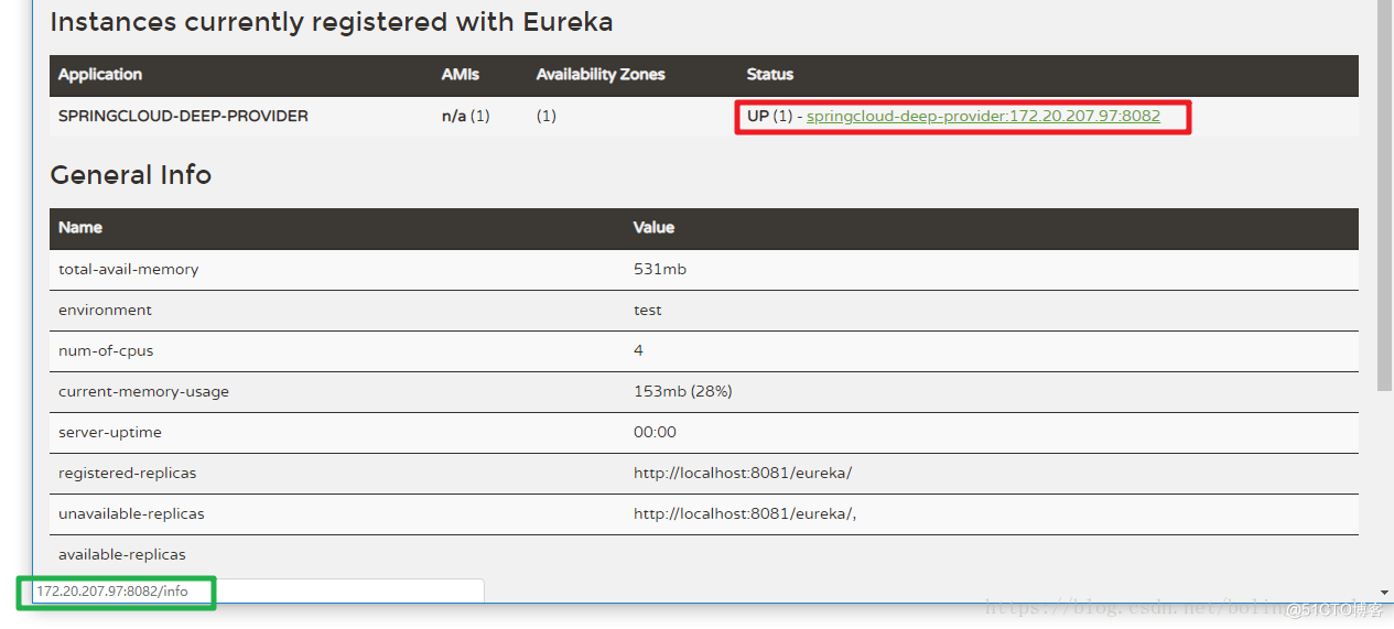
Eureka registration information configuration memo

ORB-SLAM3论文概述

Scala Basics (II): variables and data types

Oracle连接问题以及解决方案

OpenAPI 3.0 specification - Food Guide
随机推荐
Redis Lua sandbox bypass command execution (cve-2022-0543)
基於鄰接矩陣的廣度優先遍曆
版本管理工具使用
How to improve code execution efficiency with arm pipeline
Technology is to be studied
Redis6.0 new feature - ACL (permission control list) implements the restriction of user executable commands and keys
数据库的授权
Chapter I: essential information collection of penetration test
用指南针交易股票安全吗?指南针是如何交易股票的,需要开户吗
MySQL必须掌握4种语言!
How do I fix the iPhone green screen problem? Try these solutions
Sloppy formula
Is it safe to open a securities account at the school of Finance and business in 2022?
# 云原生训练营毕业总结
财富自由技能:把自己产品化
【缺陷检测】基于matlab GUI印刷电路板自动缺陷检测【含Matlab源码 1912期】
DF reports an error stale file handle
在同花顺网上开户安全吗?如何网上开一个券商账户
Depth first traversal based on adjacency table
应届毕业生谈毕业的故事