当前位置:网站首页>Understand chisel language. 23. Chisel sequential circuit (III) -- detailed explanation of chisel shift register
Understand chisel language. 23. Chisel sequential circuit (III) -- detailed explanation of chisel shift register
2022-07-27 09:40:00 【github-3rr0r】
Chisel Sequential circuits ( 3、 ... and )——Chisel shift register (Shift Register) Detailed explanation
The last article introduced Chisel Counters and some advanced uses , It's a lot of content , You will definitely gain a lot from learning . In addition to the counter , Another kind of register is widely used , That is the shift register . This article will introduce shift registers and Chisel Shift register in , It also includes parallel output 、 Shift register loaded in parallel .
shift register
The shift register is a set of flip flops connected in sequence , Every register ( trigger ) The output of is used as the input of the next register . Here is a 4 Schematic diagram of stage shift register :

The shift register circuit will be on each clock tick Move data from left to right , So... In the diagram above 4 Level shift register circuit realizes from din To dout Four beat delay output . It should be noted that , The above diagram uses four registers , But in fact, the implementation is equivalent to a shift register , The same is true of the latter two shift registers .
Below Chisel The code implements a shift register :
val shiftReg = Reg(UInt(4.W))
shiftReg := Cat(shiftReg(2, 0), din)
val dout = shiftReg(3)
This code needs to be explained , It has done so many things :
- Created a 4 Bit register
shiftReg; - Set the low of the shift register 3 Bit and input
dinuseCatSplice up , As the next input of the register ; - The most significant bit of the value of the register (Most Significant Bit,MSB) As
doutOutput .
It's easy to understand . Shift registers are usually used to convert serial data to parallel data or parallel data to serial data , These two shift registers are introduced in the following two sections .
Parallel output shift register
The shift register configured with serial input and parallel output can convert a serial input stream into parallel words , This shift register may be used for serial port (UART) Receiving function of . The following figure is a 4 Bit parallel output shift register , The output of each trigger is connected to a single bit output :
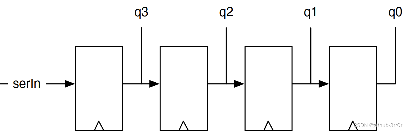
After four clock cycles , The circuit will put a 4 Bit serial data word is converted into a 4 Bit parallel data word q. In this case , Let's assume that No 0 position ( Its lowest ) Input first, so when reading the complete word, it reaches the last register . The following code implements such a 4 Bit parallel output shift register :
val outReg = RegInit(0.U(4.W))
outReg := Cat(serIn, outReg(3, 1))
val q = outReg
This shift register outReg Initialize to 0, Then we go from MSB Start moving in , That is, the register value is shifted to the right ,4 After a period , The result of parallel output q Just register outReg Value .
Parallel input shift register
The shift register of parallel input serial output configuration can put a parallel input word ( byte ) The stream is converted to a serial output stream , This shift register may be used for serial port (UART) Sending function . Here is a 4 Schematic diagram of shift register with bit parallel input :

You can see , Each shift register has an input Mux To choose which data to load , If load The signal is set , Then load d, Otherwise load 0 Or the value of the previous register , That is, displacement , In a nutshell load Load when valid ,load Shift output when invalid . use Chisel The code implementation is as follows :
val loadReg = RegInit(0.U(4.W))
when(load) {

    loadReg := d
} .otherwise {

    loadReg := Cat(0.U, loadReg(3, 1))
}
val serOut = loadReg(0)
Look for the otherwise In statement block Cat call , During the shift, the most significant bit will be filled 0, The shifted least significant bit is connected as an output to serOut On .
Conclusion
This article introduces the implementation of shift register and two commonly used shift registers , It will be very useful in realizing serial communication , It may have some inspiration for the later high-speed interface design . The register related content ends here , But in digital design , There are not only registers that can store the state signal of the circuit , Memory (Memory) You can also save status information , In processor design, memory is also used for storing program code and data , So it's absolutely important . In the next article, we will talk about it in detail in a long length Chisel Memory implementation in , Coming soon .
边栏推荐
猜你喜欢

Community attribute of BGP
【云原生 • DevOps】一文掌握容器管理工具 Rancher

吃透Chisel语言.26.Chisel进阶之输入信号处理(二)——多数表决器滤波、函数抽象和异步复位

语音直播系统——开发推送通知需要遵守的原则

Read the paper snunet CD: a densely connected Siamese network for change detection of VHR images

How to install cpolar intranet penetration on raspberry pie
![[wechat applet] lunar calendar and Gregorian calendar are mutually converted](/img/6e/ad01756f8da54901a64c5323e4b747.png)
[wechat applet] lunar calendar and Gregorian calendar are mutually converted

1344. Included angle of clock pointer

Proposed relocation! 211 the new campus of China University of Petroleum (East China) is officially opened!

监控神器:Prometheus 轻松入门,真香!
随机推荐
Proposed relocation! 211 the new campus of China University of Petroleum (East China) is officially opened!
1640. Can you connect to form an array -c language implementation
基于 FPGA 按键控制呼吸灯原理、仿真及验证全过程
XML概述
2022 software test interview questions 200 big factory interview true questions brushed to get 10K positions
July training (day 06) - sliding window
吃透Chisel语言.25.Chisel进阶之输入信号处理(一)——异步输入与去抖动
七月集训(第10天) —— 位运算
July training (day 08) - prefix and
Write yourself a year-end summary. Happy New Year!
Community attribute of BGP
Read the paper snunet CD: a densely connected Siamese network for change detection of VHR images
July training (day 20) - binary search tree
C# 给Word每一页设置不同文字水印
swagger-editor
深度剖析分库分表最强辅助Sharding Sphere
一骑入秦川——浅聊Beego AutoRouter是如何工作
BGP的社团属性
The command prompt cannot start mysql, prompting system error 5. Access denied. terms of settlement
【CTF】ciscn_ 2019_ es_ two