当前位置:网站首页>Analysis of 8253a register
Analysis of 8253a register
2022-06-30 23:19:00 【InfoQ】
1 8253 Introduce
1.1 The difference between a counter and a timer
- Timer : System daily clock 、 Memory refresh 、 Control the speaker .
- Counter : Count the pulse signal provided by the peripheral . The same thing : Count the pulses . Difference : Whether the time interval of pulses is regular , The timer has , Counter not .
1.2 8254 function
1.3 8253 and 8254 The difference between
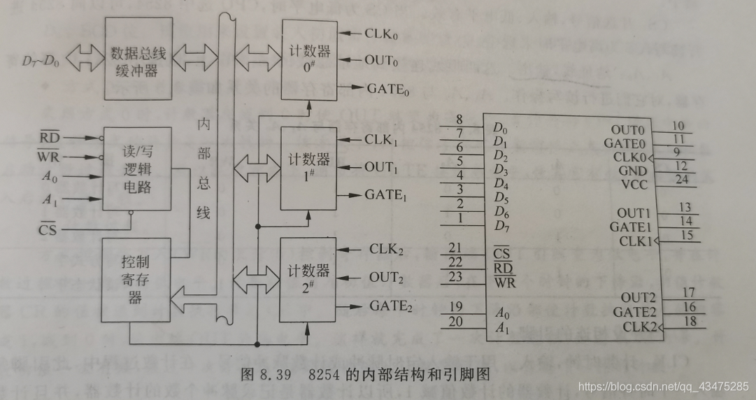
1.4 8254 Internal structure and pin diagram of
1.5 8253 External pins
1.5.1 8254 And CPU Connected pins

1.5.2 8254 Pins connected to peripherals
2 8254 Programmable register
2.1 Way word


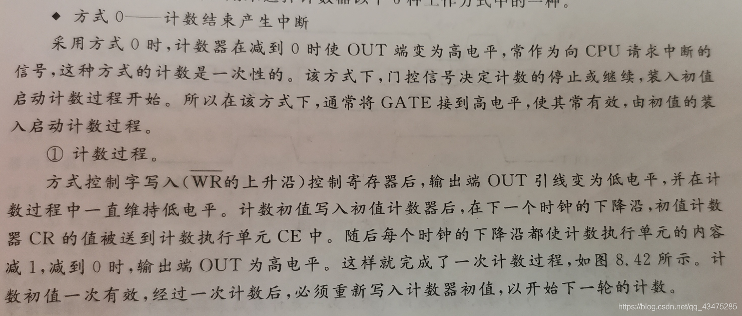
2.1.1 The way 0: The count ends with an interrupt


2.1.2 The way 1: Programmable monostable pulse


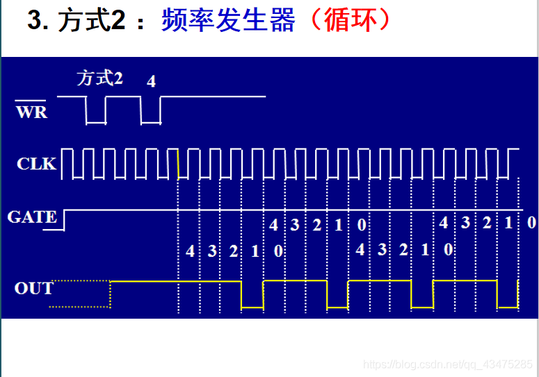
2.1.3 The way 2: Frequency generator ( Frequency divider )


2.1.4 The way 3: Square wave generator


2.1.5 The way 4: Software triggered strobe signal


2.1.6 The way 5: Hardware triggered strobe signal


边栏推荐
- How to use dataant to monitor Apache APIs IX
- C language array interception, C string by array interception method (c/s)
- [fundamentals of wireless communication-13]: illustrated mobile communication technology and application development-1-overview
- 基金销售行为规范及信息管理
- MIT doctoral dissertation optimization theory and machine learning practice
- Fund managers' corporate governance and risk management
- Warmup preheating learning rate "suggestions collection"
- E-commerce seckill system
- Solve arm_ release_ ver of this libmali is ‘g2p0-01eac0‘,rk_ so_ Ver is' 4 ', libgl1 mesa dev will not be installed, and there are unsatisfied dependencies
- AtCoder Beginner Contest 255
猜你喜欢

Maxpool2d explanation -- Application in arrays and images

Esp8266 becomes client and server
![[leetcode] [SQL] notes](/img/8d/160a03b9176b8ccd8d52f59d4bb47f.png)
[leetcode] [SQL] notes

Redis的事务和锁机制

什么是SRM系统,如何规范公司内部采购流程

5g smart building solution 2021

未来十年世界数字化与机器智能展望

Redis - 01 cache: how to use read cache to improve system performance?

Detailed explanation of conv2d -- use in arrays and images

在线客服系统代码_h5客服_对接公众号_支持APP_支持多语言
随机推荐
KubeVela 1.4:让应用交付更安全、上手更简单、过程更透明
[Android, kotlin, tflite] mobile device integration deep learning light model tflite (object detection)
Classic case of multithreading
The sandbox is being deployed on the polygon network
How to mention hot fix and cherry pick
JMeter cross thread parameter association requires no script
[无线通信基础-13]:图解移动通信技术与应用发展-1-概述
Ms17-010 Eternal Blue vulnerability of MSF
What are the contents and processes of software validation testing? How much does it cost to confirm the test report?
Fastjson V2 simple user manual
CNN classic network model details -lenet-5 (pytorch Implementation)
[Android, kotlin, tflite] mobile device integration depth learning light model tflite (image classification)
如何区分平台安全和网上炒作?网络投机有哪些止损技巧?
异步過渡方案—Generator
Introduction to machine learning compilation course learning notes lesson 2 tensor program abstraction
CesiumJS 2022^ 源码解读[6] - 三维模型(ModelExperimental)新架构
206 page Shanghai BIM Technology Application and development report 2021
RIDE:获取图片base64
35家巨头科技公司联合组成元宇宙标准论坛组织
1175. Disposition des nombres premiers / échange de doigts II 104. Nombre de permutations