当前位置:网站首页>Conversion of world coordinate system, camera coordinate system and image coordinate system
Conversion of world coordinate system, camera coordinate system and image coordinate system
2022-07-24 06:01:00 【Didi'cv】
Camera calibration notes
- Coordinate transformation
- Four different types of coordinate systems
- Coordinate transformation
Coordinate transformation
Before, I just stayed at the stage of being able to use , I have never understood the principle of calculation , I read through the article of the boss today , The writing is concise and comprehensive , Thank you thank you ~~ It is hereby recorded that , For personal notes only
Post a link , Thank you very much. ~
https://blog.csdn.net/weixin_44278406/article/details/112986651
https://blog.csdn.net/guyuealian/article/details/104184551
Four different types of coordinate systems
Convert three-dimensional objects into two-dimensional coordinates on photos , It is transformed by four coordinate systems .
1. World coordinate system
The world coordinate system is a special coordinate system , It establishes the reference frame needed to describe other coordinate systems . Can use the world coordinate system to describe the position of other coordinate systems , Instead of using bigger 、 The external coordinate system describes the world coordinate system . In a non-technical sense , The world coordinate system establishes the largest coordinate system we care about , It doesn't have to be the whole world .
use ( X w , Y w , Z w ) (X_w,Y_w,Z_w) (Xw,Yw,Zw) To express , The world coordinate system can get the camera coordinate system through rotation and Translation .
2. Camera coordinate system
At the geometric center of the camera lens ( Light heart ) Origin , The coordinate system satisfies the right-hand rule , use ( X c , Y c , Z c ) (X_c,Y_c,Z_c) (Xc,Yc,Zc) To express ; The optical axis of the camera is in the coordinate system Z Axis ,X Axis horizontal ,Y Vertical axis .
3. Image physical coordinate system
With CCD The center of the image is the origin , Coordinates from ( x , y ) (x, y) (x,y) Express , Unit of image coordinate system , Usually mm , The coordinate origin is the intersection of the camera optical axis and the imaging plane ( In general , This intersection is close to the center of the image )
CCD, English full name :Charge coupled Device, Chinese full name : Charge coupled device , Can be called CCD image sensor .CCD It's a semiconductor device , It can convert optical images into digital signals . CCD The tiny photosensitive material implanted on the is called pixel (Pixel). A piece of CCD The more pixels it contains , The higher the picture resolution it provides .
4. Image pixel coordinate system
Actually , When we mention an image , It usually refers to the pixel coordinate system of the image . The origin of the pixel coordinate system is in the upper left corner , And the unit is pixels .
Set the origin of the image coordinate system O 1 O_1 O1 , Convert to O 0 O_0 O0 In the coordinate system of the origin . Reason for use :
- If you use the image coordinate system , Company mm, In fact, it is not easy to measure specific images , If according to the unified pixel standard , It is easier to measure the quality of the image
- If you use the image coordinate system , Then there are four quadrants , There will be a problem of positive and negative numbers , But after converting to pixel coordinate system , All are integers . In subsequent operations and operations , Are simplified a lot .
Coordinate transformation
Pinhole Model (The basic pinhole model). This model is mathematically from three-dimensional space to two-dimensional plane (image plane or focal plane) The central projection of , By a 3 × 4 3 × 4 3×4 Projection matrix P = K [ R ∣ t ] P = K [ R | t ] P=K[R∣t] To describe , K K K For camera internal reference (internal camera parameters), [ R ∣ t ] [R|t] [R∣t] For external reference (external parameters).
World coordinates → Camera coordinates ( Rigid transformation )
[ X c Y c Z c 1 ] = [ R t 0 1 ∗ 3 1 ] [ X w Y w Z w 1 ] \begin{bmatrix}X_c \\ Y_c \\ Z_c \\ 1 \end{bmatrix} = \begin{bmatrix}R & t\\\\ 0_{1*3} & 1 \end{bmatrix} \begin{bmatrix}X_w \\ Y_w \\ Z_w \\ 1 \end{bmatrix} ⎣⎡XcYcZc1⎦⎤=⎣⎡R01∗3t1⎦⎤⎣⎡XwYwZw1⎦⎤
X c , Y c , Z c X_c,Y_c,Z_c Xc,Yc,Zc Represents camera coordinates ; X w , Y w , Z w X_w,Y_w,Z_w Xw,Yw,Zw Represents world coordinates ;R Represents the orthogonal unit rotation matrix ,t Represents three-dimensional translation vector .
According to the rotation angle, the rotation matrix in three directions can be obtained , The rotation matrix is their product : R = R x ∗ R y ∗ R z R = R_x * R_y * R_z R=Rx∗Ry∗Rz
By the way, record the formula of three rotation matrices , Often forget .
Around the X X X rotate θ \theta θ degree
[ X c Y c Z c ] = [ 1 0 0 0 c o s θ s i n θ 0 − s i n θ c o s θ ] [ X w Y w Z w ] = R x [ X w Y w Z w ] \begin{bmatrix}X_c\\Y_c\\Z_c\end{bmatrix} = \begin{bmatrix}1&0&0\\0&cos\theta&sin\theta\\0&-sin\theta&cos\theta\end{bmatrix} \begin{bmatrix}X_w\\Y_w\\Z_w\end{bmatrix}=R_x\begin{bmatrix}X_w\\Y_w\\Z_w\end{bmatrix} ⎣⎡XcYcZc⎦⎤=⎣⎡1000cosθ−sinθ0sinθcosθ⎦⎤⎣⎡XwYwZw⎦⎤=Rx⎣⎡XwYwZw⎦⎤
Around the Y Y Y Shaft rotation θ \theta θ degree
[ X c Y c Z c ] = [ c o s θ 0 − s i n θ 0 1 0 s i n θ 0 c o s θ ] [ X w Y w Z w ] = R y [ X w Y w Z w ] \begin{bmatrix}X_c\\Y_c\\Z_c\end{bmatrix} = \begin{bmatrix}cos\theta&0&-sin\theta\\0&1&0\\sin\theta&0&cos\theta\end{bmatrix} \begin{bmatrix}X_w\\Y_w\\Z_w\end{bmatrix}=R_y\begin{bmatrix}X_w\\Y_w\\Z_w\end{bmatrix} ⎣⎡XcYcZc⎦⎤=⎣⎡cosθ0sinθ010−sinθ0cosθ⎦⎤⎣⎡XwYwZw⎦⎤=Ry⎣⎡XwYwZw⎦⎤
Around the Z Z Z Shaft rotation θ \theta θ degree
[ X c Y c Z c ] = [ c o s θ s i n θ 0 − s i n θ c o s θ 0 0 0 1 ] [ X w Y w Z w ] = R z [ X w Y w Z w ] \begin{bmatrix}X_c\\Y_c\\Z_c\end{bmatrix} = \begin{bmatrix}cos\theta&sin\theta&0\\-sin\theta&cos\theta&0\\0&0&1\end{bmatrix} \begin{bmatrix}X_w\\Y_w\\Z_w\end{bmatrix}=R_z\begin{bmatrix}X_w\\Y_w\\Z_w\end{bmatrix} ⎣⎡XcYcZc⎦⎤=⎣⎡cosθ−sinθ0sinθcosθ0001⎦⎤⎣⎡XwYwZw⎦⎤=Rz⎣⎡XwYwZw⎦⎤
Camera coordinates → Image coordinate system ( Center of the projection )
The relationship between camera coordinate system and image coordinate system is perspective , Use similar triangles to calculate .
The matrix written in homogeneous coordinates is multiplied by
Z c [ x y 1 ] = [ f 0 0 0 0 f 0 0 0 0 1 0 ] [ X c Y c Z c 1 ] = [ K ∣ 0 ] [ X c Y c Z c 1 ] Zc \begin{bmatrix}x\\y\\1\end{bmatrix} = \begin{bmatrix}f&0&0&0\\0&f&0&0\\0&0&1&0 \end{bmatrix} \begin{bmatrix}X_c\\Y_c\\Z_c\\1\end{bmatrix} = \begin{bmatrix}K|0\end{bmatrix} \begin{bmatrix}X_c\\Y_c\\Z_c\\1\end{bmatrix} Zc⎣⎡xy1⎦⎤=⎣⎡f000f0001000⎦⎤⎣⎡XcYcZc1⎦⎤=[K∣0]⎣⎡XcYcZc1⎦⎤
among f Representative focal length , That is, the camera coordinate system and image coordinate system are in Z The difference on the shaft . Now the projection point p The unit is still mm, Not at all pixel, It is not convenient for subsequent operations .
Image coordinate system → Pixel coordinate system ( discretization )
The origin of the pixel coordinate system is in the upper left corner , And the unit is pixels . Both the pixel coordinate system and the image coordinate system are on the imaging plane , It's just that their origins and units of measurement are different . The origin of the image coordinate system is the intersection of the camera optical axis and the imaging plane , Usually it's the midpoint of the imaging plane, or principal point. The unit of the image coordinate system is mm, Belongs to a physical unit , And the unit of the pixel coordinate system is pixel, We usually describe a pixel as several rows and columns . So the conversion between the two is as follows : among dx and dy Represents how much each column and row represents mm, namely 1pixel=dx mm
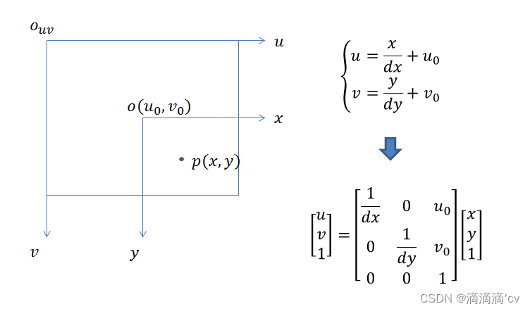
Z c [ u v 1 ] = [ 1 d x 0 u 0 0 1 d y v 0 0 0 1 ] [ f 0 0 0 0 f 0 0 0 0 1 0 ] [ R t 0 1 ∗ 3 1 ] [ X w Y w Z w 1 ] Zc \begin{bmatrix}u\\v\\1\end{bmatrix} = \begin{bmatrix}\frac{1}{d_x}&0&u_0\\0&\frac{1}{d_y}&v_0\\0&0&1 \end{bmatrix} \begin{bmatrix}f&0&0&0\\0&f&0&0\\0&0&1&0 \end{bmatrix} \begin{bmatrix}R & t\\\\ 0_{1*3} & 1 \end{bmatrix} \begin{bmatrix}X_w \\ Y_w \\ Z_w \\ 1 \end{bmatrix} Zc⎣⎡uv1⎦⎤=⎣⎡dx1000dy10u0v01⎦⎤⎣⎡f000f0001000⎦⎤⎣⎡R01∗3t1⎦⎤⎣⎡XwYwZw1⎦⎤
among [ 1 d x 0 u 0 0 1 d y v 0 0 0 1 ] [ f 0 0 0 0 f 0 0 0 0 1 0 ] \begin{bmatrix}\frac{1}{d_x}&0&u_0\\0&\frac{1}{d_y}&v_0\\0&0&1 \end{bmatrix} \begin{bmatrix}f&0&0&0\\0&f&0&0\\0&0&1&0 \end{bmatrix} ⎣⎡dx1000dy10u0v01⎦⎤⎣⎡f000f0001000⎦⎤ Is the camera internal parameter matrix , [ R t 0 1 ∗ 3 1 ] \begin{bmatrix}R & t\\\\ 0_{1*3} & 1 \end{bmatrix} ⎣⎡R01∗3t1⎦⎤ External parameter matrix . Camera calibration is to solve the parameters of these two matrices .

边栏推荐
- "Statistical learning methods (2nd Edition)" Li Hang Chapter 17 latent semantic analysis LSA LSI mind mapping notes and after-school exercise answers (detailed steps) Chapter 17
- A small problem in labelme to VOC code
- Machine learning (zhouzhihua) Chapter 2 model selection and evaluation notes learning experience
- IoTP2PGate 两台物联网设备点对点通信快速实现方案
- Qt 使用纯代码画图异常
- 如何解决训练集和测试集的分布差距过大问题
- vscode 多行注释总是会自动展开的问题
- 读取csv文件的满足条件的行并写入另一个csv中
- AD1256
- [MYCAT] MYCAT installation
猜你喜欢

YOLOv5学习总结(持续更新)

"Statistical learning methods (2nd Edition)" Li Hang Chapter 14 clustering method mind map notes and after-school exercise answers (detailed steps) K-means hierarchical clustering Chapter 14

Xshell远程访问工具

Chapter IV decision tree summary

"Statistical learning methods (2nd Edition)" Li Hang Chapter 13 introduction to unsupervised learning mind map notes

Statistical learning methods (2nd Edition) Li Hang Chapter 22 summary of unsupervised learning methods mind mapping notes

Loss after cosine annealing decay of learning rate

"Statistical learning methods (2nd Edition)" Li Hang Chapter 16 principal component analysis PCA mind map notes and after-school exercise answers (detailed steps) PCA matrix singular value Chapter 16
MySql下载,及安装环境设置
How to solve the problem of large distribution gap between training set and test set
随机推荐
systemctl + journalctl
synergy局域网实现多主机共享键鼠(amd、arm)
Unicast, multicast, broadcast, tool development, introduction to QT UDP communication protocol development and source code of development tools
labelme转voc代码中的一个小问题
【深度学习】手把手教你写“手写数字识别神经网络“,不使用任何框架,纯Numpy
Chapter 5 neural network
[MYCAT] MYCAT installation
day5-jvm
Qt char型转QString型 16进制与char型 转 16进制整型
[activiti] Introduction to activiti
JSON. Dumps() function parsing
如何在网页上下载视频
KMP代码分布详解
[MYCAT] MYCAT sub database and sub table
Qt 使用纯代码画图异常
++cnt1[s1.charAt(i) - ‘a‘];
[raspberry pie 4B] VII. Summary of remote login methods for raspberry pie xshell, putty, vncserver, xrdp
[MYCAT] MYCAT configuration file
Raspberry pie is of great use. Use the campus network to build a campus local website
PDF文本合并