当前位置:网站首页>Question B of 2016 Sichuan Ti Cup Electronic Design Competition
Question B of 2016 Sichuan Ti Cup Electronic Design Competition
2022-06-26 11:55:00 【Full stack programmer webmaster】
Hello everyone , I meet you again , I'm your friend, Quan Jun .
B topic : Automatic tracking car 1. Mission Design Make an automatic tracking car . The trolley adopts one piece TI company LDC1314 or LDC1000 An inductive digital converter is used as a tracking sensor , Automatically follow the clockwise direction at the specified plane runway . The runway is marked with a diameter 0.6~0.9mm Fine wire , According to the plan 1 Schematic dimensions of , Stick it on the runway with scotch tape . The radius of all arcs in the figure is 20cm±2cm.
chart 1 Runway diagram 2. requirement (1) In the figure 1 A starting point is arbitrarily specified in the straight-line area where the trolley is located ( End ), The trolley shall be marked according to the iron wire set on the runway , Automatically complete a lap around the track . The time must not exceed 10 minute . The track wire must be kept under the vertical projection of the trolley when the trolley is running . If there is a breach , Every time 2 branch . (40 branch ) (2) Real time display of the traveling distance and running time of the trolley . (10 branch ) (3) Place on any straight wire 4 About... In diameter 19mm Nickel plated steel coins ( The fifth set of RMB 1 Dimes ), The edge of the coin clings to the wire , Pictured 1 Shown . When the car passes by coins, it can find and give an audible prompt . (20 branch ) (4) Try to reduce the running time of the trolley running around the runway . (25 branch ) (5) other . ( 5 branch ) (6) Design report (20 branch ) term Objective primary coverage Full marks Scheme demonstration Compare and choose , Scheme description 3 Theoretical analysis and calculation System related parameter design 5 Circuit and programming System composition , Principle block diagram and circuit diagram of each part , System software and flow chart 5 Test plan and test results Test result integrity , Analysis of test results 5 Structure and standardization of design report Abstract , Body structure specification , Completeness and accuracy of charts 2 total branch 20
3. explain (1) The automatic tracking car is allowed to be refitted with a toy car . The trolley is powered by its own battery , Do not use external power supply . The size of the trolley shall be such that its projection on the ground does not exceed A4 Paper size . After the trolley runs automatically , There shall be no manual interference with the movement of the trolley , Such as remote control . (2) Inductive sensors are used in addition to TI It's distributed by the company LDC1314 Off chip , You can also use LDC1000 Chip or module , The quantity is limited to one . Do not use any other type of sensor for tracking . (3) Except for the designated iron wire , Do not add any additional marks . There should be no additional metal objects near the runway .
Video game playback : We all know that the main devices used in the competition will be notified in advance , So I set up the car and adjusted the inductive sensor before the game with my teammates LDC1000. But after the topic comes out , We decided to adopt LDC1314(LDC1314 It's also TI An inductive sensor of the company 、 And LDC1000 comparison 、1314 More powerful , comparison ldc1000 Single channel this sensor contains 4 External metal detection input of the channel ). As for the trolley, it is mainly the carrier and executive part of other modules , When controlling, make corresponding actions and reactions according to the feedback information of the sensor .
One 、 Hardware design
1、 Overall design of the system The overall block diagram of the system is shown in Fig 1 Shown , The power module supplies power to the single-chip microcomputer and L298N Drive power supply . Single chip microcomputer reading LDC1000 And the pulse obtained by infrared velocimetry , Then the distance and time are displayed on the LCD , And feedback control of the motor .
2、 Module design (1) Power module Considering that the trolley is powered by the battery of mobile power supply , The control of power consumption is particularly important here . Because the efficiency of switching regulated power supply is higher than that of general linear regulated power supply , The switching power supply module is used to provide a stable power supply for the single chip microcomputer . Mainly used in LM2576adj For power PWM The output of the control is adjustable, and the switching power supply circuit based on the step-down power supply control chip is used as the 5V Constant voltage input . Motor drive circuit (L298N Motor drive circuit ) Use the battery output voltage 11V As power supply input , Reduce the unnecessary energy loss .
(2): The choice of master chip With STM32F103VET6 Single chip microcomputer as the core control mode .STM32F103VET6 It is a product made by Italian French semiconductor company ARM cortex-m3 For the kernel 32 Bit microcontroller .STM32F103VCT6 Yes 512KBFlash,48K Of RAM,8 A timer ,3 individual SPI,2 individual I2C etc. , The film is rich in resources . The operating frequency can reach 72MHz, It can meet various control requirements .ST The company's control chip is especially based on cortex-M The series of control chips have ultra-high cost performance and are very suitable for various industrial control fields 、 This video game is mainly based on STM32F103VET6 Single chip microcomputer is the microcontroller designed this time .
(3) Metal track detection module (ldc1000 perhaps ldc1314) As I said before , After the game started, we gave up the adjustment ldc1000 Instead of ldc1314, Fortunately, there are ldc1000 Experience , On the first day, our group made ldc1000 Module , The corresponding driver code is also written . Then start debugging the car tracking , It was used PID Algorithm , according to P,D,I The order of . There is no safety tube due to the switching power supply used on the way , In the process of staying up late, I accidentally connected the power supply reversely and burned it 2576 Switching power supply chip ( I don't know if it is really safe to add a safety tube , But the back of the fuse has never been burned , After all, the game , It's best not to create complications ) In this way, we adjusted it in the morning of the third day PID, The car can barely walk the whole journey to complete the tracking , The excitement in my heart , So we continue to revise PID Parameters , Strive for better results . But the fourth morning , I don't know what's going on LDC1314 Burned , I don't know what went wrong . The saddest thing is that the school teachers no longer give us LDC1314. After disappointment , I took out LDC1000, Or use it ldc1000, Not at first ldc1000 Because it has only one channel —— Only one coil can be connected , and LDC1314 There are four channels —— It can connect four coils , therefore LDC1314 We take it for granted that it is better in tracing , However, the time has passed datasheet With the actual verification and the students in the competition group ,LDC1314 The detection distance and sensitivity are obviously less than LDC1000. Officially because of this ldc’1000 It is also the choice of many successful people , because ldc’1314 It's too short , Slight data loss ( It does not detect ) It's easy for the car to get off the track .LDC1000 The module measures data from LDC1000 The register reads the lower eight bits and the upper eight bits , Combined into a valid value , Then the equivalent parallel resistance and resonance frequency can be obtained by calculation , We can deduce the distance of the object off-line circle . From the fourth day , We switch to LDC1000—— There are two options : ① Use a coil , utilize PID To judge the change of direction ( This is how I met a senior brother who is not from my school ), But the difficulty is 1、 The coil should be larger , The induction intensity should be stronger .2、 The car should be well controlled ( The motor and steering gear are easy to use ).3、PID The algorithm parameters should be selected very well , Otherwise, it's easy to get out of orbit . ② Use two coils , Placed on the left and right to judge the direction , add PID More precise control . Because we use a DC motor ( No motor is coded ), Secondly, the steering gear is not very good , And I don't have a good big coil ( The school teacher called PCB The coil effect is extremely poor !), Worry that one coil can not be adjusted , Therefore, it is also a problem for us to switch the device by using two coils ( One 、 With what switch . Two 、 The effect of switching frequency on the effect .) There are also two options :1、 Field pipe ;2、 Relay . Finally, the relay was selected , The frequency changes slightly ( You bet • The relay has certain influence on the data collected by the coil , And the current changes a little ), Fortunately, it was finally realized . 3、 Motor drive module This design uses L298N As a motor drive .L298N It's a double H Bridge motor driver chip , Each of them H Bridges can provide 2A Current , And equipped with 2 An enabling end , Be able to control the output . The supply voltage range of the power part is 2.5-48v, Logical part 5v Power supply , Accept 5vTTL level .
4、 Other modules Other related modules such as relay driver 、1602 The principle of small modules such as LCD interface circuit is relatively simple , I won't go into details here .
To sum up : One : Stay up late and be sure to slow down , Be careful , It's easy to break things because you're too sleepy , Do more harm than good ( The game lasts seven days , Every day for the first five days 4 Take a nap , From eight , After two days of continuous overnight ) It is easy to make mistakes when you are tired and sleepy , We burned 1314 And the power board is very tired, sleepy and impatient . Two : The relay drive uses a current sink , Do not use pull current ( I couldn't drive the relay at first , Even 2003 Neither. , I can't figure it out , Later, I checked the information and found , Stuck for half a day ) 3、 ... and :PID Parameters must correspond to a system , When the system changes, the parameters change 、 During parameter adjustment, attention should be paid to the sequence and order of parameter adjustment . Generally follow the order : a. Determine the proportional gain P Determine the proportional gain P when , First remove PID Integral and differential terms of , It's usually to make Ti=0、 Td=0, PID For pure proportional adjustment . Enter the value set to the maximum value allowed by the system 60%~70%, from 0 Gradually increase the ratio Example gain P, Until the system oscillates ; And vice versa , From the proportional gain at this time P Gradually decrease , until System oscillation disappears , Record the proportional gain at this time P, Set up PID Proportional gain of P Is the current value of 60%~70%. Proportional gain P Debugging completed . b. Determine the integral time constant Ti Proportional gain P after , Set a larger integral time constant Ti Initial value of , Then gradually decrease Small Ti, Until the system oscillates , And then in reverse , Gradually increasing Ti, Until the system oscillation disappears . Record this moment of Ti, Set up PID Integral time constant of Ti Is the current value of 150%~180%. Integral time constant Ti Debugging completed . c. Determine the integral time constant Td Proportional gain P after , Set a larger integral time constant Ti Initial value of , Then gradually decrease Small Ti, Until the system oscillates , And then in reverse , Gradually increasing Ti, Until the system oscillation disappears . Record this moment of Ti, Set up PID Integral time constant of Ti Is the current value of 150%~180%. Integral time constant Ti Debugging completed . Four : Use SPI3 Can't use at the same time JTAG Multiplexed clock , You need to turn off its multiplexed clock ( I will study the details , The game used SPI3 It didn't go well at first , close JTAG The multiplexed clock is ok 了 ) 5、 ... and :LDC1314 and LDC1000 The chip can change the value range of detection , Increase the difference value , But I don't think it can change the sensitivity , Instead, the sensitivity is changed by adjusting the coil inductance and the connected capacitance ( See TI Online computing tool on the official website ) 6、 ... and : choose PID Algorithm time , Feedback must be reliable , That is, the selected sensor feedback data must be accurate or the sensor must be adjusted accurately .
Finally, there is a little regret : First of all 、 I feel that I am not well prepared , A lot of things should be prepared by yourself , Especially the car , I regret using one with poor performance , DC motor ( The same voltage and speed of the wheels on both sides are obviously different ), The small angle of the steering gear is poor , Or not , Or turn the angle . The other is the coil. I regret not playing it myself , It's really bad to play that at school , Some are not tested at all . second 、 Regret giving up LDC1000, Should be LDC1314 Indeed, the detection distance is too short in my hardware , Almost wiped the ground ,LDC1000 It's even better , Almost twice the distance , To tell the truth, at first I thought TI Selling his new 1314 That's what I care about . It turns out that when the hardware is not very good ,LDC1000 It's good to get a little •. Third 、 Stay up late , Lesson from blood .
Finally, I'll give you a few pictures of my works
Here's part of the code :
include
include “usart.h”
include “ldc1000.h”
include “1602.h”
include “beep.h”
include “delay.h”
include “motor.h”
include “pwm_tim5.h”
include “step_motor.h”
include “ldc_intruput.h”
include “pid.h”
extern unsigned long ProximityData; //LDC On Proximity Data extern unsigned char flag; extern u16 CCR3_Val , CCR4_Val ;// The rear wheel 2,3 The steering gear 0
unsigned long red_ProximityData, bule_ProximityData;
void display(unsigned long temp,u16 adr); void jichu_ProximityData(void);
unsigned long jichu_red,jichu_bule; u16 time,distance;
uint8_t table[10]=”0123456789”; uint8_t table1[10]=”Time:”; uint8_t table2[10]=”distance:”; extern u16 CCR3_Val; u8 i;
int main (void) { NVIC_Configuration(); delay_init(); USART1_Config(); inct(); beep_Init(); SPI_LDC_Init(); TIM5_PWM_Init(); TIM7_ldc_Init(60000-1,72-1); MOTOR_Init(); jidainqi_Init();
write_com(0x80);
delay(10);
for(i=0;i<6;i++)
write_data(table1[i]);
write_com(0x80+0x0a);
write_data('s');
write_com(0x80+0x40);for(i=0;i<9;i++) write_data(table2[i]); write_com(0x80+0x4e); write_data(‘c’); write_com(0x80+0x4f); write_data(‘m’);
jichu_ProximityData();
Rear_wheel_direction(0);
while(1)
{
    if(jidianqi==0)
    {
    LDCRead();
        if(ProximityData>9000&ProximityData<14000)
        {
                red_ProximityData=ProximityData;
        display(red_ProximityData,0x80+0x49);
        }
        else if(ProximityData<9000&ProximityData>8000)
        {
                            beep=1;
                    delay_ms(100);
                    beep=0;
        }
        else if(ProximityData<8000)
        {
bule_ProximityData=ProximityData;// display(bule_ProximityData,0x80+0x4F); } else if(ProximityData>=16000) // COINS { beep=1; delay_ms(100); beep=0; } delay_ms(50); jidianqi=1; } else if(jidianqi==1) { LDCRead(); if(ProximityData>9000&ProximityData<14000) { red_ProximityData=ProximityData; // display(red_ProximityData,0x80+0x49); } // else if(ProximityData<9000&ProximityData>8000) // { // beep=1; // delay_ms(100); // beep=0; // } else if(ProximityData<8000) { bule_ProximityData=ProximityData; // display(bule_ProximityData,0x80+0x4F); } else if(ProximityData>16000) // COINS { beep=1; delay_ms(100); beep=0; } delay_ms(50); jidianqi=0; }
} } void display(unsigned long temp,u16 adr) { uint8_t i; write_com(0x04); delay(30); write_com(adr); while(temp) { i=temp%10; write_data(table[i]); temp/=10; } write_com(0x06); } void jichu_ProximityData() // Get the base value { u8 j; for(j=0;j<10;j++) { if(jidianqi==0) { LDCRead(); if(ProximityData>9000&&ProximityData<18000) { red_ProximityData=ProximityData; // display(red_ProximityData,0x80+0x49); } else if(ProximityData<9000) { bule_ProximityData=ProximityData; // display(bule_ProximityData,0x80+0x4F); } else if(ProximityData>=18000) // COINS { beep=1; delay_ms(100); beep=0; } jidianqi=1; delay_ms(100); } else if(jidianqi==1) { LDCRead(); if(ProximityData>9000&&ProximityData<18000) { red_ProximityData=ProximityData; // display(red_ProximityData,0x80+0x49); } else if(ProximityData<9000) { bule_ProximityData=ProximityData; // display(bule_ProximityData,0x80+0x4F); } else if(ProximityData>=18000) // COINS { beep=1; delay_ms(100); beep=0; } jidianqi=0; delay_ms(100); } } jichu_red=red_ProximityData; jichu_bule=bule_ProximityData; }
LDC1000 drive
ifndef LDC24L01_H
define LDC24L01_H
include
define GPIO_LDC GPIOC
define GPIO_LDC_CSN_Pin GPIO_Pin_5
define GPIO_LDC_CE_Pin GPIO_Pin_2
define GPIO_LDC_IQ_Pin GPIO_Pin_4
define SPI_NOP 0XFF// An empty instruction is used to read the status register
/****** Register address area *********/
define LDC1000_CMD_REVID 0x00
define LDC1000_CMD_RPMAX 0x01
define LDC1000_CMD_RPMIN 0x02
define LDC1000_CMD_SENSORFREQ 0x03
define LDC1000_CMD_LDCCONFIG 0x04
define LDC1000_CMD_CLKCONFIG 0x05
define LDC1000_CMD_THRESHILSB 0x06
define LDC1000_CMD_THRESHIMSB 0x07
define LDC1000_CMD_THRESLOLSB 0x08
define LDC1000_CMD_THRESLOMSB 0x09
define LDC1000_CMD_INTCONFIG 0x0A
define LDC1000_CMD_PWRCONFIG 0x0B
define LDC1000_CMD_STATUS 0x20
define LDC1000_CMD_PROXLSB 0x21
define LDC1000_CMD_PROXMSB 0x22
define LDC1000_CMD_FREQCTRLSB 0x23
define LDC1000_CMD_FREQCTRMID 0x24
define LDC1000_CMD_FREQCTRMSB 0x25
// LDC BITMASKS
define LDC1000_BIT_AMPLITUDE 0x18
define LDC1000_BIT_RESPTIME 0x07
define LDC1000_BIT_CLKSEL 0x02
define LDC1000_BIT_CLKPD 0x01
define LDC1000_BIT_INTMODE 0x07
define LDC1000_BIT_PWRMODE 0x01
define LDC1000_BIT_STATUSOSC 0x80
define LDC1000_BIT_STATUSDRDYB 0x40
define LDC1000_BIT_STATUSWAKEUP 0x20
define LDC1000_BIT_STATUSCOMP 0x10
define TEST_RPMAX_MAX 0x13 /*< maximum calibration value for RPMAX /
define TEST_RPMAX_MIN 0x10 /*< minimum calibration value for RPMAX /
define TEST_RPMAX_INIT TEST_RPMAX_MIN+1 /*< RPMAX initial value /
define TEST_RPMIN_MAX 0x3D /*< maximum calibration value for RPMIN /
define TEST_RPMIN_MIN 0x3A /*< minimum calibration value for RPMIN /
define TEST_RPMIN_INIT TEST_RPMIN_MIN+1 /*< RPMIN initial value /
// Final Test Range
define TEST_RP_MSB_MAX 0x12 /*< maximum value for proximity data /
define TEST_RP_MSB_MIN 0x0A /*< minimum value for proximity data /
define TEST_FC_MAX 0x0D5D /*< maximum value for frequency counter /
define TEST_FC_MIN 0x0D39 /*< minimum value for frequency counter /
/****** Macro definition area *********/
define LDC_CSN_HIGH() GPIO_SetBits(GPIO_LDC, GPIO_LDC_CSN_Pin)
define LDC_CSN_LOW() GPIO_ResetBits(GPIO_LDC, GPIO_LDC_CSN_Pin) //csn Buy low
define LDC_Read_IRQ() GPIO_ReadInputDataBit (GPIO_LDC, GPIO_LDC_IQ_Pin)
/****** Function declaration area *********/ extern void SPI_LDC_Init(void);//spi The initialization u8 SPI_LDC_RW(u8 data); static void SPI_LDC_WriteReg(u8 reg,u8 data);// towards reg Write in the register data static u8 SPI_LDC_ReadReg(u8 reg);// Read the value of the specified status register void LDC1000_init(void); void LDCRead(void); extern void MY_SPI_Init(void); void TIM3_NVIC_Configuration(void); static void TIM3_GPIO_Config(void); static void TIM3_Mode_Config(void); void TIM3_Init(void); float CountRp(void); unsigned long Fsensor(unsigned long lFcount); unsigned long Fsensor(unsigned long lFcount); unsigned long CountInductor(unsigned long lFsensor);
endif
include “ldc1000.h”
include “usart.h”
include “math.h”
define SPI_RWBIT 0x80
define Fext 32768 //32768 Hz
define ResponseTime 6144
define CapVal 0.0001 //1uF*/
unsigned long ProximityData; unsigned long FrequencyData; unsigned char flag; volatile u32 speed=999;
__IO uint16_t DataRcv[5] ;
/************* initialization spi*********************** * work can : Initialize wildfire spi * shape ginseng : void * return return value :void * To prepare notes : *******************************************************/ extern void MY_SPI_Init(void) { SPI_InitTypeDef SPI_InitStr; GPIO_InitTypeDef GPIO_InitStr;
/* Can make GPIOB,GPIOD, Multiplexing function clock */
RCC_APB2PeriphClockCmd(RCC_APB2Periph_GPIOA|RCC_APB2Periph_GPIOC|RCC_APB2Periph_AFIO, ENABLE);

/* Can make SPI1 The clock */
RCC_APB2PeriphClockCmd(RCC_APB2Periph_SPI1, ENABLE);

/* For hardware stm32 Of SPI To configure */
/* To configure  SPI_LDC_SPI Of  SCK,MISO,MOSI Pin ,GPIOA^5,GPIOA^6,GPIOA^7 */
GPIO_InitStr.GPIO_Pin = GPIO_Pin_5|GPIO_Pin_6|GPIO_Pin_7;
GPIO_InitStr.GPIO_Speed = GPIO_Speed_50MHz;
GPIO_InitStr.GPIO_Mode = GPIO_Mode_AF_PP; // Reuse function
GPIO_Init(GPIOA, &GPIO_InitStr);

/* Pair slave LDC24L01 Control angle configuration of */
/* To configure CE Pin ,GPIOA^2 and  CSB  Pin */
GPIO_InitStr.GPIO_Pin = GPIO_LDC_CSN_Pin;
GPIO_InitStr.GPIO_Speed = GPIO_Speed_50MHz;
GPIO_InitStr.GPIO_Mode = GPIO_Mode_Out_PP;
GPIO_Init(GPIOC, &GPIO_InitStr);

/* For hardware stm32 Of SPI To configure */
/* To configure SPI_LDC_SPI Of IRQ Pin ,GPIOA^3*/
GPIO_InitStr.GPIO_Pin = GPIO_LDC_IQ_Pin;
GPIO_InitStr.GPIO_Speed = GPIO_Speed_50MHz;
GPIO_InitStr.GPIO_Mode = GPIO_Mode_IPU ;  // Pull up input
GPIO_Init(GPIOC, &GPIO_InitStr);

/*  This is a custom macro , For lifting csn Pin ,LDC Enter the idle state  */
LDC_CSN_HIGH();

SPI_InitStr.SPI_Direction = SPI_Direction_2Lines_FullDuplex; // Two wire full duplex
SPI_InitStr.SPI_Mode = SPI_Mode_Master;                     // Main mode
SPI_InitStr.SPI_DataSize = SPI_DataSize_8b;                 // data size 8 position
SPI_InitStr.SPI_CPOL = SPI_CPOL_High;                       // Clock polarity , Low in free time
SPI_InitStr.SPI_CPHA = SPI_CPHA_2Edge;                      // The first 1 Edges are valid , The rising edge is the sampling time
SPI_InitStr.SPI_NSS = SPI_NSS_Soft;                         //NSS The signal is generated by software
SPI_InitStr.SPI_BaudRatePrescaler = SPI_BaudRatePrescaler_4;  //8 frequency division ,9MHz
SPI_InitStr.SPI_FirstBit = SPI_FirstBit_MSB;                // High in the former
SPI_InitStr.SPI_CRCPolynomial = 7;                          //CRC Verify reset
SPI_Init(SPI1, &SPI_InitStr);

/* Enable SPI1  */
SPI_Cmd(SPI1, ENABLE);}
/************* towards LDC Chinese Reading / Write a byte ************* * work can : towards LDC Chinese Reading / Write a byte * shape ginseng : Written data * return return value : Read the acquired data * To prepare notes : *******************************************************/ u8 SPI_LDC_RW(u8 data) // towards LDC Read and write a byte in { /* When SPI Wait when the transmit buffer is not empty */ while (SPI_I2S_GetFlagStatus(SPI1, SPI_I2S_FLAG_TXE) == RESET);
/*  adopt  SPI2 Send a byte of data  */
SPI_I2S_SendData(SPI1, data);

 /*  When SPI Wait while the receive buffer is empty  */
while (SPI_I2S_GetFlagStatus(SPI1, SPI_I2S_FLAG_RXNE) == RESET);

/* Return the byte read from the SPI bus */
return SPI_I2S_ReceiveData(SPI1);}
/************* towards LDC Write value of the specified register ************* * work can : towards LDC Write value of the specified register * shape ginseng : reg:LDC The order of + Register address . * data: The data to be written to the register * return return value : The state of the register * To prepare notes : *******************************************************/ static void SPI_LDC_WriteReg(u8 reg,u8 data) {
// LDC_CE_LOW();// Enter standby mode 1, Low power mode , In this mode LDC Can receive data LDC_CSN_LOW();// Pull it down csn Piece of optional signal , Can make LDC Of spi transmission
SPI_LDC_RW(reg);// towards LDC Send command and register number

SPI_LDC_RW(data);// Write data to the register just specified

LDC_CSN_HIGH();// pull up csn Piece of optional signal , Release LDC Of spi Transmission complete ;}
/************* Read LDC Specified register value ************* * work can : Read LDC Specified register value * shape ginseng : reg:LDC Register address . * return return value : Data in the status register * To prepare notes : *******************************************************/ static u8 SPI_LDC_ReadReg(u8 reg) { u8 Reg_Value;
// LDC_CE_LOW();// Enter standby mode 1, Low power mode , In this mode LDC Can receive data LDC_CSN_LOW();// Pull it down csn Piece of optional signal , Can make LDC Of spi transmission
SPI_LDC_RW(reg|SPI_RWBIT);// Select register
Reg_Value = SPI_LDC_RW(SPI_NOP);

LDC_CSN_HIGH();// pull up csn Piece of optional signal , Release LDC Of spi Transmission complete ;

return Reg_Value;}
/********************************************************** * @brief: LDC1000 Initialize configuration ,ps: stay SPI Data bits are configured in 16 Data length , so * When sending data, you can send the address and value together with the operation * @param: none * @return: none ***********************************************************/ void LDC1000_init(void) { // SPI_Write(LDC1000_CMD_RPMAX<<8|0xff); SPI_LDC_WriteReg(LDC1000_CMD_RPMAX,0x31); // To configure Rp_MAX(0x01) register SPI_LDC_WriteReg(LDC1000_CMD_RPMIN,0x1b); // To configure Rp_MIN(0x02) register SPI_LDC_WriteReg(LDC1000_CMD_SENSORFREQ,0x94); // To configure Sensor Frequency(0x03) register SPI_LDC_WriteReg(LDC1000_CMD_LDCCONFIG,0x17); // To configure LDC Configuration(0x04) register SPI_LDC_WriteReg(LDC1000_CMD_CLKCONFIG,0x00); // To configure Clock Configuration(0x05) register , // Use TBCLK As a clock source // To configure INTB Output flag bits for comparison (status of Comparator output) SPI_LDC_WriteReg(LDC1000_CMD_THRESHILSB,0x50); // To configure Comparator Threshold High(0x06) Register low 8 position SPI_LDC_WriteReg(LDC1000_CMD_THRESHIMSB,0x14); // To configure Comparator Threshold High(0x07) Register high 8 position SPI_LDC_WriteReg(LDC1000_CMD_THRESLOLSB,0xC0); // To configure Comparator Threshold Low(0x08) Register low 8 position SPI_LDC_WriteReg(LDC1000_CMD_INTCONFIG,0x02); // To configure INTB Pin Configuration(0x0A), SPI_LDC_WriteReg(LDC1000_CMD_PWRCONFIG,0x01); // To configure Power Configuration(0x0B) register , // by Active Mode, Enable to transform }
/********************************************************** * @brief: Use SPI Read LDC1000 Data in * @param: none * @return: none ***********************************************************/ void LDCRead(void) { // LDC_CSN_LOW(); ProximityData = 0; FrequencyData = 0; while(LDC_Read_IRQ()!=0) printf(“read 1 failed!”); DataRcv[0] = SPI_LDC_ReadReg(LDC1000_CMD_PROXLSB); // Write the... To be read Proximity Data LSB Register address (0x21) //printf(“0 %d\r\n”,DataRcv[0]); //SPI_Read(&DataRcv[0]); // Read the value in the above register , And deposit in DataRcv[0] ProximityData|= DataRcv[0] ; while(LDC_Read_IRQ()!=0) printf(“read 2 failed!”); DataRcv[1] = SPI_LDC_ReadReg(LDC1000_CMD_PROXMSB); // Write the... To be read Proximity Data MSB Register address (0x22) //printf(“1 %d\r\n”,DataRcv[1]); //SPI_Read(&DataRcv[1]); // Read the value in the above register , And deposit in DataRcv[1] ProximityData|= (DataRcv[1]<<8) ; // Combine into ProximityData while(LDC_Read_IRQ()!=0) printf(“read 3 failed!”); DataRcv[2] = SPI_LDC_ReadReg(LDC1000_CMD_FREQCTRLSB); // Write the... To be read Frequency Counter Data LSB Register address (0x23) //printf(“2 %d\r\n”,DataRcv[2]); //SPI_Read(&DataRcv[2]); // Read the value in the above register , And deposit in DataRcv[2] FrequencyData|= DataRcv[2] ; while(LDC_Read_IRQ()!=0) printf(“read 4 failed!”); DataRcv[3] = SPI_LDC_ReadReg(LDC1000_CMD_FREQCTRMID); // Write the... To be read Frequency Counter Data Mid-Byte Register address (0x24) //printf(“3 %d\r\n”,DataRcv[3]); //SPI_Read(&DataRcv[3]); // Read the value in the above register , And deposit in DataRcv[3] FrequencyData|= (DataRcv[3]<<8) ; while(LDC_Read_IRQ()!=0); DataRcv[4] = SPI_LDC_ReadReg(LDC1000_CMD_FREQCTRMSB); // Write the... To be read Frequency Counter Data MSB Register address (0x25) //printf(“4 %d\r\n\n\n”,DataRcv[4]); //SPI_Read(&DataRcv[4]); // Read the value in the above register , And deposit in DataRcv[4] FrequencyData|= (DataRcv[4]<<16) ; // Combine into FrequencyData
// LDC_CSN_HIGH(); } //——————————————————// //———————-Rp Calculation ————————-// //————-unsigned long CountRp() —————–// //——————————————————// float CountRp(void) { float Y; unsigned Code; float Rp;
Code =ProximityData;
Y = ((float)Code/32768.0); printf(“Y value: %f\r\n”,Y); Rp = (float)(((float)TEST_RPMAX_MAX*(float)TEST_RPMAX_MIN) / ((float)TEST_RPMAX_MIN*(1-Y)+(float)TEST_RPMAX_MAX*(float)Y));
return Rp; }
//——————————————————// //——————-LC Evaluation of oscillation frequency ——————–// //—–unsigned long Fsensor(unsigned long lFcount)—–//、 // Input parameters :lFcount: Fre Code Value //——————————————————// unsigned long Fsensor(unsigned long lFcount) { unsigned long lFsensor; unsigned long Fcount;
Fcount = lFcount; lFsensor = (1*Fext*ResponseTime)/(3*Fcount);
return lFsensor; } //——————————————————// //———————L Inductance evaluation ———————-// //–unsigned long CountInductor(unsigned long lFsensor)-// // Input parameters :lFsensor: LC Resonant frequency //——————————————————// unsigned long CountInductor(unsigned long lFsensor) { unsigned long Fsensor; unsigned long L;
Fsensor = lFsensor;
L = (unsigned long)(pow(10,12)* 1/(CapVal * pow(2*3.14*Fsensor,2)) ); //uH
return L; } extern void SPI_LDC_Init(void) { TIM3_Init(); MY_SPI_Init(); LDC1000_init(); flag=1; }
/* * Function name :TIM3_NVIC_Configuration * describe :TIM3 Interrupt priority configuration * Input : nothing * Output : nothing */ void TIM3_NVIC_Configuration(void) { NVIC_InitTypeDef NVIC_InitStructure;
NVIC_PriorityGroupConfig(NVIC_PriorityGroup_0);
NVIC_InitStructure.NVIC_IRQChannel = TIM3_IRQn;
NVIC_InitStructure.NVIC_IRQChannelPreemptionPriority = 0;
NVIC_InitStructure.NVIC_IRQChannelSubPriority = 3;
NVIC_InitStructure.NVIC_IRQChannelCmd = ENABLE;
NVIC_Init(&NVIC_InitStructure);}
static void TIM3_GPIO_Config(void) { GPIO_InitTypeDef GPIO_InitStructure;
RCC_APB1PeriphClockCmd(RCC_APB1Periph_TIM3, ENABLE);
RCC_APB2PeriphClockCmd(RCC_APB2Periph_GPIOB, ENABLE);GPIO_InitStructure.GPIO_Pin = GPIO_Pin_0|GPIO_Pin_1; GPIO_InitStructure.GPIO_Mode = GPIO_Mode_AF_PP; // Multiplexing push pull output GPIO_InitStructure.GPIO_Speed = GPIO_Speed_50MHz;
GPIO_Init(GPIOB, &GPIO_InitStructure);}
static void TIM3_Mode_Config(void) { TIM_TimeBaseInitTypeDef TIM_TimeBaseStructure; TIM_OCInitTypeDef TIM_OCInitStructure;
/* PWM Signal level jump value  */
u16 TIM_CCR3_Val = 2;

/* -----------------------------------------------------------------------
TIME3  Can output  4  road  PWM  wave form :
TIME3_CH1   ------  PA6
TIME3_CH2   ------  PA7
TIME3_CH3   ------  PB0
TIME3_CH4   ------  PB1
----------------------------------------------------------------------- */

/* Time base configuration */
TIM_TimeBaseStructure.TIM_Period = 3;       // When the timer starts from 0 Count to 999, That is to say 1000 Time , For a timing period
TIM_TimeBaseStructure.TIM_Prescaler = 0;        // Set prescaler : prescale 72, That is to say 1KHz
TIM_TimeBaseStructure.TIM_ClockDivision = 0;    // Set the clock division factor : Regardless of the frequency
TIM_TimeBaseStructure.TIM_CounterMode = TIM_CounterMode_Up;  // Upcount mode

TIM_TimeBaseInit(TIM3, &TIM_TimeBaseStructure);
TIM_ClearFlag(TIM3, TIM_FLAG_Update);                                       /*  Clear overflow interrupt flag  */
TIM_ITConfig(TIM3,TIM_IT_Update,ENABLE);

/* PWM1 Mode configuration: Channel3 */
TIM_OCInitStructure.TIM_OCMode = TIM_OCMode_PWM1;       // Configure to PWM Pattern 1
TIM_OCInitStructure.TIM_OutputState = TIM_OutputState_Enable;
TIM_OCInitStructure.TIM_Pulse = TIM_CCR3_Val;      // Set jump value , When the counter counts to this value , The level jumps
TIM_OCInitStructure.TIM_OCPolarity = TIM_OCPolarity_High;  // When the timer count value is less than CCR1_Val High level when

TIM_OC3Init(TIM3, &TIM_OCInitStructure);     // Enabling channel 1

    TIM_OCInitStructure.TIM_OCMode = TIM_OCMode_PWM1;       // Configure to PWM Pattern 1
TIM_OCInitStructure.TIM_OutputState = TIM_OutputState_Enable;
TIM_OCInitStructure.TIM_Pulse = TIM_CCR3_Val;      // Set jump value , When the counter counts to this value , The level jumps
TIM_OCInitStructure.TIM_OCPolarity = TIM_OCPolarity_High;  // When the timer count value is less than CCR1_Val High level when

TIM_OC4Init(TIM3, &TIM_OCInitStructure);     // Enabling channel 1

TIM_OC4PreloadConfig(TIM3, TIM_OCPreload_Enable);    // Use CCR3 Shadow register of register ( Changes do not occur until an update event occurs )

//TIM_ARRPreloadConfig(TIM3, ENABLE);            //  Can make TIM3 Overload register ARR

/* TIM3 enable counter */
TIM_Cmd(TIM3, ENABLE); // Enable timer 3}
void TIM3_Init(void) { //TIM3_NVIC_Configuration(); TIM3_GPIO_Config(); TIM3_Mode_Config(); }
include “pid.h”
include “sys.h”
include “motor.h”
include “delay.h”
extern unsigned long ProximityData,red_ProximityData,bule_ProximityData; extern unsigned long jichu_red,jichu_bule; extern u16 CCR3_Val,CCR4_Val;
void pid_pwm_red()// { int chazhi_z = 0, pid_val_z = 0, weifen_z=0; // float pid_p_z = 1.05,pid_i_z = 0.1, pid_d_z = 2.5; static int jifen_z = 0, l_chazhi_z= 0, l_val_z= 0; float pid_p_z = 1.8,pid_i_z = 0, pid_d_z = 0; chazhi_z = red_ProximityData – jichu_red; jifen_z += chazhi_z; if(jifen_z> 400) { jifen_z= 400; } else if(jifen_z < -400) { jifen_z = -400; } weifen_z = chazhi_z – l_chazhi_z; if(weifen_z > 10) { weifen_z = 10; } if(weifen_z < -10) { weifen_z = -10; } pid_val_z = chazhi_z*pid_p_z+jifen_z*pid_i_z+weifen_z*pid_d_z; if(pid_val_z>0) { TIM_SetCompare3(TIM5, CCR3_Val+pid_val_z); TIM_SetCompare4(TIM5, CCR4_Val-pid_val_z); } else { TIM_SetCompare3(TIM5, CCR3_Val-pid_val_z); TIM_SetCompare4(TIM5, CCR4_Val+pid_val_z); } l_chazhi_z = chazhi_z; }
void pid_pwm_blue(void) { int chazhi_y = 0, pid_val_y = 0, weifen_y=0; // float pid_p_y = 1.9, pid_i_y = 1, pid_d_y = 3; static int jifen_y = 0, l_chazhi_y= 0, l_val_= 0; float pid_p_y = 1.2, pid_i_y = 0.1, pid_d_y =0.05; //1.5 0.05 chazhi_y = bule_ProximityData-jichu_bule; jifen_y+= chazhi_y; if(jifen_y> 200) { jifen_y= 200; } else if(jifen_y < -200) { jifen_y = -200; } weifen_y = chazhi_y – l_chazhi_y; if(weifen_y > 10) { weifen_y = 10; } if(weifen_y < -10) { weifen_y = -10; } pid_val_y = chazhi_y*pid_p_y+jifen_y*pid_i_y+weifen_y*pid_d_y; if(pid_val_y>0) { TIM_SetCompare3(TIM5, CCR3_Val-pid_val_y); TIM_SetCompare4(TIM5, CCR4_Val+pid_val_y); } else { TIM_SetCompare3(TIM5, CCR3_Val+pid_val_y); TIM_SetCompare4(TIM5, CCR4_Val+pid_val_y); } l_chazhi_y = chazhi_y; }
Publisher : Full stack programmer stack length , Reprint please indicate the source :https://javaforall.cn/133967.html Link to the original text :https://javaforall.cn
边栏推荐
- Several problems encountered in setting up the environment in the past two days
- Splicing full paths and uploading multiple pictures of laravel admin when laravel uses OSS
- Flannel's host GW and calico
- [probability theory] conditional probability, Bayesian formula, correlation coefficient, central limit theorem, parameter estimation, hypothesis test
- 证券账户一般需要在哪里开通 开户安全吗
- HUST网络攻防实践|6_物联网设备固件安全实验|实验三 FreeRTOS-MPU 保护绕过
- Machine learning linear regression - Experimental Report
- MOS管基本原理,单片机重要知识点
- HUST network attack and defense practice | 6_ IOT device firmware security experiment | Experiment 3 freertos-mpu protection bypass
- 科技兴关,荣联与天津海关共建基因组数据库及分析平台
猜你喜欢

HUST网络攻防实践|6_物联网设备固件安全实验|实验三 FreeRTOS-MPU 保护绕过

TCP interview
女性科学家的流失
loggie 编码以及换行符测试

Easyx----- C language implementation 2048
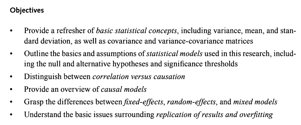
Statistical genetics: Chapter 2, the concept of statistical analysis

Prospering customs through science and technology, Ronglian and Tianjin Customs jointly build a genomic database and analysis platform

Apiccloud implements the document download and preview functions

Omni channel member link - tmall member link 3: preparation of member operation content
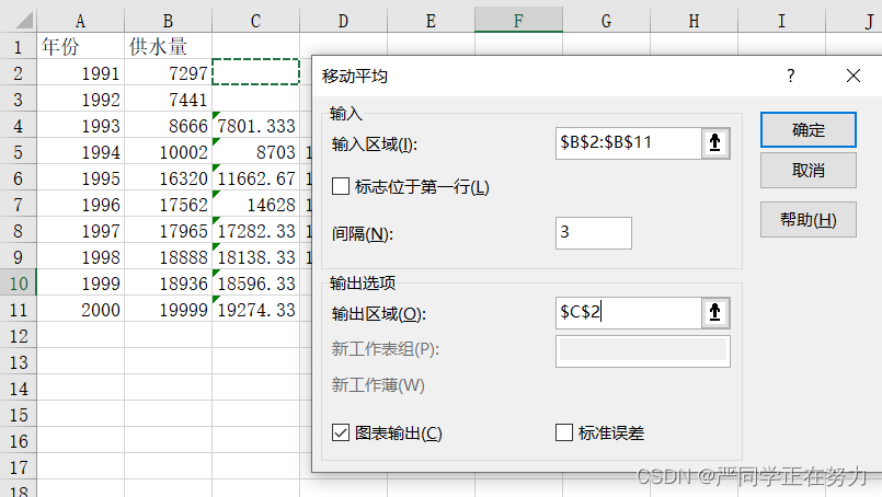
介绍一下实现建模中可能用到的时间序列预测之线性二次移动平均,Excel的简单操作

随机推荐
HUST network attack and defense practice | 6_ IOT device firmware security experiment | Experiment 3 freertos-mpu protection bypass
11、 Box styles and user interface
初探Protostuff的使用[通俗易懂]
24 database interview questions that must be mastered!
.net中,日志组件 Nlog,SerialLog, Log4Net的用法
Hello! Forward proxy!
How do consumer goods enterprises formulate membership interests?
The most complete kubernetes core command of the latest version so far
[graduation season · advanced technology Er] I remember the year after graduation
TCP面试
CG骨骼动画
APICloud 实现文档下载和预览功能
证券账户一般需要在哪里开通 开户安全吗
NFS共享存储服务安装
证券账户可以开通 开户安全吗
This paper introduces the simple operation of realizing linear quadratic moving average of time series prediction that may be used in modeling and excel
Statistical genetics: Chapter 1, basic concepts of genome
Statistical genetics: Chapter 2, the concept of statistical analysis
【Redis 系列】redis 学习十六,redis 字典(map) 及其核心编码结构
Machine Learning Clustering - Experimental Report