当前位置:网站首页>STM32 - PWM learning notes
STM32 - PWM learning notes
2022-07-26 03:00:00 【The poorest are beggars and immortals will always come out】
One 、 Can produce PWM Timer introduction
STM32 In addition to TIM6 and 7. Other timers can be used to generate PWM Output . One of the advanced timers TIM1 and TIM8 It can produce as many as 7 On the road PWM Output . And universal timers can also generate up to 4 On the road PWM Output .
Two 、 All the way PWM The corresponding channel


3、 ... and 、 Related configuration
1、 Channels used IO Mouth configuration ( Configure according to the selected channel )
	// Configure output I/O Pin
    // Set this pin to multiplex output function , Output TIM3 CH2 Of PWM Pulse shape 	GPIOB.5
	GPIO_InitStructure.GPIO_Pin = GPIO_Pin_5; //TIM_CH2
	GPIO_InitStructure.GPIO_Mode = GPIO_Mode_AF_PP;  // Multiplexing push pull output
	GPIO_InitStructure.GPIO_Speed = GPIO_Speed_50MHz;
	GPIO_Init(GPIOB, &GPIO_InitStructure);// initialization GPIO
2、 Timer configuration
   // Timer configuration
   // initialization TIM3
	TIM_TimeBaseStructure.TIM_Period = arr; // Set the value of the auto reload register cycle for the next update event load activity
	TIM_TimeBaseStructure.TIM_Prescaler =psc; // Set as TIMx Prescaled value of clock frequency divisor
	TIM_TimeBaseStructure.TIM_ClockDivision = 0; // Set the clock split :TDTS = Tck_tim
	TIM_TimeBaseStructure.TIM_CounterMode = TIM_CounterMode_Up;  //TIM Upcount mode
	TIM_TimeBaseInit(TIM3, &TIM_TimeBaseStructure); // according to TIM_TimeBaseInitStruct The parameter specified in TIMx Unit of time base
3、PWM Output mode configuration
Among them, we mainly pay attention to the first 、 The third configuration .
The first configuration :
TIM_OCInitStructure.TIM_OCMode =TIM_OCMode_PWM1 / TIM_OCMode_PWM2;
Configure the output comparison mode , When it comes to PWM1 when : The current value of the counter Output the effective level when it is lower than the set value
When it comes to PWM2 when : The current value of the counter Output the effective level when it is higher than the set value
The third configuration :
TIM_OCInitStructure.TIM_OCPolarity = TIM_OCPolarity_High;
Configure whether the effective level is high level or low level ,TIM_OCPolarity_High: The active level is high
TIM_OCPolarity_Low: The active level is low
    // Timer channel configuration
	// initialization TIM3 Channel2 PWM Pattern
	TIM_OCInitStructure.TIM_OCMode = TIM_OCMode_PWM2; // Select timer mode :TIM Pulse width modulation mode 2( Model 2 : When counting, when the counter value exceeds the set value, the effective level is output , Output invalid level when it is lower than )
 	TIM_OCInitStructure.TIM_OutputState = TIM_OutputState_Enable; // Compare output enable
	TIM_OCInitStructure.TIM_OCPolarity = TIM_OCPolarity_High; // Output polarity :TIM High output polarity ( The high level is the effective level , Or is the low level the effective level )
	TIM_OC2Init(TIM3, &TIM_OCInitStructure);  // according to T The specified parameter initializes the peripheral TIM3 OC2
Full configuration :
void TIM3_PWM_Init(u16 arr,u16 psc)
{
	GPIO_InitTypeDef GPIO_InitStructure;
	TIM_TimeBaseInitTypeDef  TIM_TimeBaseStructure;
	TIM_OCInitTypeDef  TIM_OCInitStructure;


  // Clock configuration
	RCC_APB1PeriphClockCmd(RCC_APB1Periph_TIM3, ENABLE);	// Enable timer 3 The clock
 	RCC_APB2PeriphClockCmd(RCC_APB2Periph_GPIOB  | RCC_APB2Periph_AFIO, ENABLE);  // Can make GPIO Peripherals and AFIO Multiplexing function module clock

	// Remap
	GPIO_PinRemapConfig(GPIO_PartialRemap_TIM3, ENABLE); //Timer3 Partial remapping   TIM3_CH2->PB5


	// Configure output I/O Pin
  // Set this pin to multiplex output function , Output TIM3 CH2 Of PWM Pulse shape 	GPIOB.5
	GPIO_InitStructure.GPIO_Pin = GPIO_Pin_5; //TIM_CH2
	GPIO_InitStructure.GPIO_Mode = GPIO_Mode_AF_PP;  // Multiplexing push pull output
	GPIO_InitStructure.GPIO_Speed = GPIO_Speed_50MHz;
	GPIO_Init(GPIOB, &GPIO_InitStructure);// initialization GPIO


	// Timer configuration
   // initialization TIM3
	TIM_TimeBaseStructure.TIM_Period = arr; // Set the value of the auto reload register cycle for the next update event load activity
	TIM_TimeBaseStructure.TIM_Prescaler =psc; // Set as TIMx Prescaled value of clock frequency divisor
	TIM_TimeBaseStructure.TIM_ClockDivision = 0; // Set the clock split :TDTS = Tck_tim
	TIM_TimeBaseStructure.TIM_CounterMode = TIM_CounterMode_Up;  //TIM Upcount mode
	TIM_TimeBaseInit(TIM3, &TIM_TimeBaseStructure); // according to TIM_TimeBaseInitStruct The parameter specified in TIMx Unit of time base


	// Timer channel configuration
	// initialization TIM3 Channel2 PWM Pattern
	TIM_OCInitStructure.TIM_OCMode = TIM_OCMode_PWM2; // Select timer mode :TIM Pulse width modulation mode 2( Model 2 : When counting, when the counter value exceeds the set value, the effective level is output , Output invalid level when it is lower than )
 	TIM_OCInitStructure.TIM_OutputState = TIM_OutputState_Enable; // Compare output enable
	TIM_OCInitStructure.TIM_OCPolarity = TIM_OCPolarity_High; // Output polarity :TIM High output polarity ( The high level is the effective level , Or is the low level the effective level )
	TIM_OC2Init(TIM3, &TIM_OCInitStructure);  // according to T The specified parameter initializes the peripheral TIM3 OC2

  TIM_OC2PreloadConfig(TIM3, TIM_OCPreload_Enable);  // Can make TIM3 stay CCR2 Pre loaded registers on ( effect : When changing the duty cycle , Can it take effect immediately )

	TIM_Cmd(TIM3, ENABLE);  // Can make TIM3


}边栏推荐
- [C Advanced] deeply explore the storage of data (in-depth analysis + interpretation of typical examples)
- 对于稳定性测试必需关注的26点
- [introduction to C language] zzulioj 1006-1010
- Autojs cloud control source code + display
- 【方向盘】使用IDEA的60+个快捷键分享给你,权为了提效(Live Template&Postfix Completion篇)
- 基础知识-网络与服务器
- Jenkins' study notes are detailed
- AMD64 (x86_64) architecture ABI document: medium
- 织梦提示你设定了字段为联动类型如何解决
- Oxycon 2022 network capture frontier conference is about to open!
猜你喜欢
ES6 advanced - inherit parent class attributes with constructors

Arthas download and startup

(pc+wap) dream weaving template vegetable and fruit websites

(9) Attribute introspection

c语言分层理解(c语言函数)
![[sql] usage of self connection](/img/92/92474343b4b4e6ea60453b4799cb55.jpg)
[sql] usage of self connection
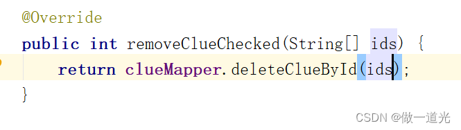
Chapter 3 business function development (delete clues)

Eslint common error reporting set

Exclusive interview with ringcentral he Bicang: empowering future mixed office with innovative MVP

这种动态规划你见过吗——状态机动态规划之股票问题(上)
随机推荐
Win11麦克风权限的开启方法
Keil's operation before programming with C language
Vofa+ serial port debugging assistant
[steering wheel] use the 60 + shortcut keys of idea to share with you, in order to improve efficiency (live template & postfix completion)
My friend took 25koffer as soon as he learned automation test. When will my function test end?
基础知识-网络与服务器
Convert rich text to normal text
(PC+WAP)织梦模板蔬菜水果类网站
测试/开发程序员老了怎么办?挥之不去残酷的事实......
信息系统项目管理师必背核心考点(五十)合同内容约定不明确规定
[translation] announce Vites 13
Basics - network and server
Study notes of pytorch deep learning practice: convolutional neural network (Advanced)
对于稳定性测试必需关注的26点
【方向盘】使用IDEA的60+个快捷键分享给你,权为了提效(重构篇)
assert _ Aligns
AMD64(x86_64)架构abi文档:中
(pc+wap) dream weaving template vegetable and fruit websites
Three years of software testing experience, salary has been stuck at 10K, how to improve and develop automated testing?
The El table header merges the first four columns into one cell