当前位置:网站首页>DMA controller 8237a
DMA controller 8237a
2022-06-30 12:03:00 【Hua Weiyun】
1 DMA System introduction
DMA(direct memory access) It is a way of directly transmitting data between peripherals and memory or between memory and memory , It's going on DMA Access time ,CPU Give up bus control , No longer use the method of input and output instructions for data access , And use a special hardware DMAC(Direct Memory Access Control) Control circuit , Reduce the middle link , Thus, the transmission rate is improved .
1.1 DMA The basic principle
DMA Direct realization I/O Data transfer with memory .
① When I/O The interface is ready , Hope to carry out DMA In operation , It's like DMAC issue DMA Request signal DRQ(DMA Request)
②DMAC Convert this request signal into CPU Bus request signal (Hold Request)
③CPU The current bus execution cycle ends , The corresponding DMAC operation , Send a reply signal HLDA(Hold Acknowledgment), here , from DMAC Take over control of the bus
④ from DMAC Addressing memory , And send out corresponding control signals (DACK,/RD,/WR), Align memory with I/O Data is exchanged directly between interfaces
⑤ When transmitting a byte of data ,DMAC Automatically modify memory address and transfer byte counter , And check whether the transmission ends
⑥DMA End of transmission ,DMAC towards CPU Send an end signal (EOP), And release the bus , bring CPU Regain bus control , Return to normal operation 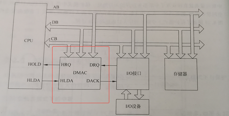
2 DMA controller 8237A
2.1 8237A summary
- 8237A It's programmable DMA controller ;
- Every 8237A Yes 4 Independent DMA passageway , Priorities are different ;
- Every DMA Channels have 4 Ways of working ;
- The maximum length of a transmission can reach 64KB;
- Multiple 8237A Chips can be cascaded , Used to expand the number of channels .
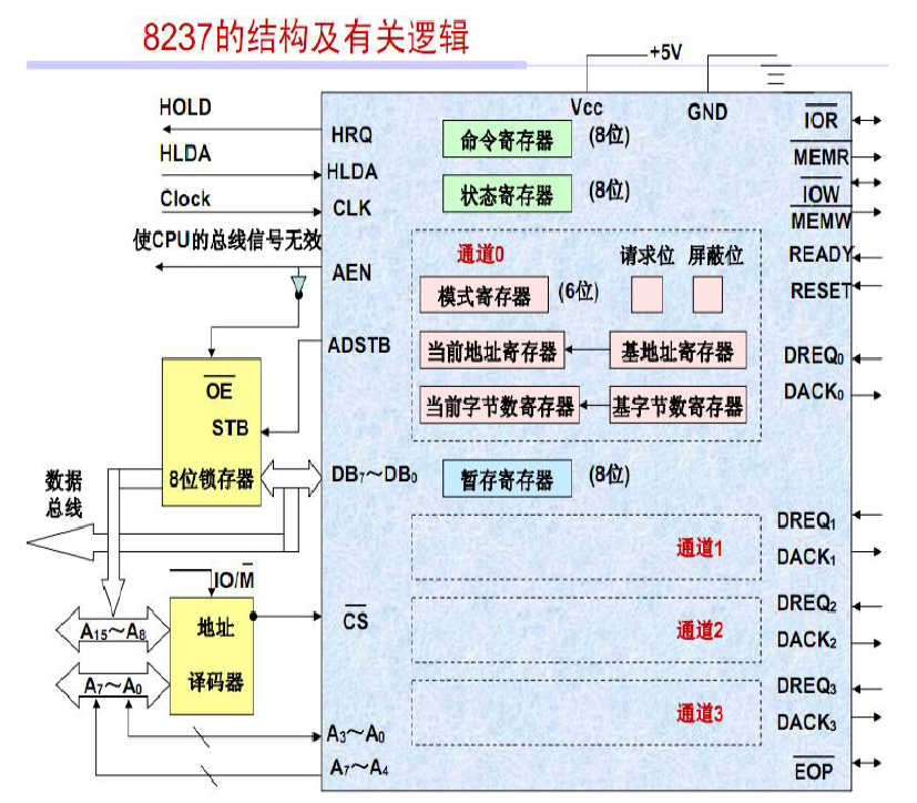
2.2 8237A internal structure
2.3 8237A Pin figure
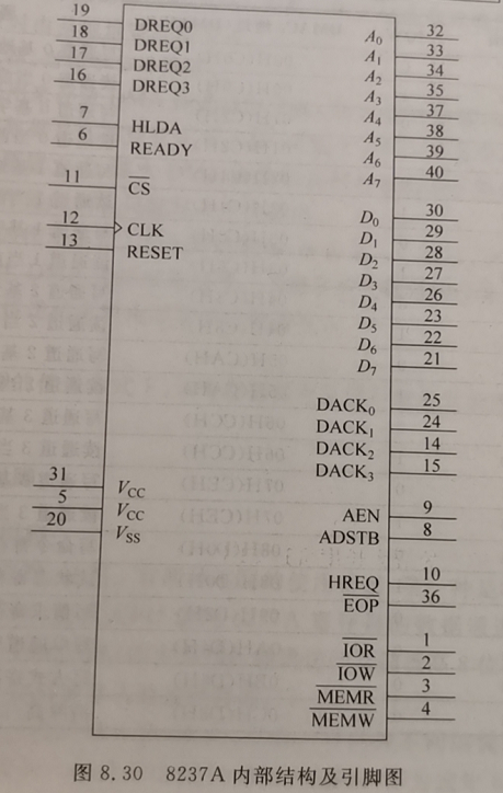
- Control signals :
(1) CLK: The clock ( Control chip internal operation and data transmission )
(2) ADSTB: Address gating
(3)/cs: Chip selection
(4) READY: Get ready
(5) AEN: The address allows
(6)/MEMR: Memory read
(7) RESET: Reset
(8)/MEMW: Memory write
(9) /IOR:I/O read
(10)/EOP : End of the process
(11) / IOW :I/O Write - Request and response signals
(1) DREQ~0~~DREQ~3~:DMA Channel request
(2) HRQ: Bus request
(3) HLDA: Bus response
(4) DACK~0~~DACK~3~:DMA Channel response - Data and address signals
(1) A~0~~A~7~: Address line
(2) DB~0~~DB~7~: cable
2.4 8237A Transmission timing
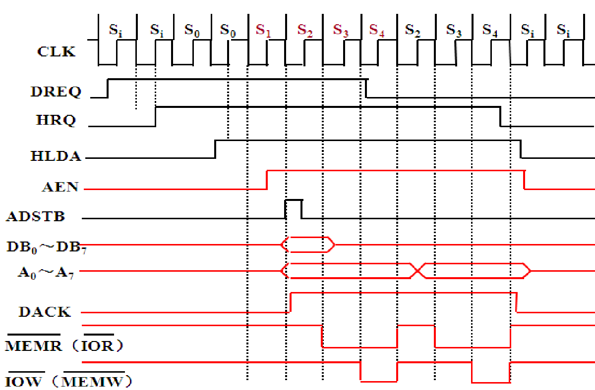
(1) Si state : Idle cycle ,Si One or more... Are detected on the falling edge of DREQ request , stay Si The next rising edge of CPU issue DMA request ,HRQ It works ;
(2) S0 state : wait for CPU Response to bus request ,S0 The rising edge of is sampled to HLDA Signal valid , The next cycle enters S1 state ;
(3) S1 state : Address permissive signal AEN It works , The storage unit is high 8 Bit address through DB0~DB7 Output , Send address strobe signal ADSTB, Falling edge to height 8 Latch bit address , Address low 8 position / By the address line A0~A7 Output , And the whole DMA Keep... During transmission ;
(4) S2 state :8237A Set the output to the outside DMA response signal DACK, The read-write signals are valid one after another ;
(5) S3 State and S4 Status for data transfer ;
(6) Block transfer mode :S4 After that, the next byte is transmitted , Address high 8 A constant , low 8 A change in , Unwanted S1 Go straight into S2, Until it happens. TC event .
(7) if S4 Data transfer cannot be completed before , May make READY For low , stay S3 and S4 Insert between Sw, To widen DMA Transmission cycle .
2.5 8237A Operation mode
2.5.1 Single byte transmission
(1) The transmission process :8237A After getting control of the bus , Send a byte , Number of bytes register minus 1, Add... To the address register 1 Or minus 1,HRQ Become invalid , Release the bus ,HRQ It's going to work again soon , Received HLDA After a valid signal , Send the next byte , Repeat the above process , Until the number of bytes goes from 0 Reduced to FFFFH, happen TC event ,DMA End of transmission .
(2) characteristic : Low efficiency , But it's guaranteed twice DMA Between transmissions CPU Opportunity to regain control of the bus .
2.5.2 Block transfer mode
(1) The transmission process : from DREQ After starting, the data will be transmitted continuously , until TC The event occurs or the external input is valid /EOP Until the signal .
(2) characteristic : One block of data can be transmitted at a time , Efficient ; But the whole DMA During transmission CPU Unable to control the bus for a long time .
2.5.3 Request delivery mode
Continuous transmission of data , Stop when one of the following three situations occurs .
(1) The number of bytes register starts from 0 Reduced to FFFFH, happen TC event ;
(2) Send a valid... From the outside The signal ;
(3) External input DREQ The signal becomes invalid .
When the third happens , When the peripheral is ready for data , The transmission can continue .
characteristic :DMA The operation can be controlled by the peripheral .
2.5.4 Cascade transmission mode
A number of films 8237A Form a master-slave pattern DMA System
2.6 8237A Transfer type
- DMA read : Data is transferred from memory to peripherals
- DMA Write : The data input by the peripheral is written into the memory
- DMA test : Empty operation , Timing signal 、 The address signal is the same as when reading and writing , But the read-write control line is invalid , Commonly used to verify .
- Memory to memory transfer : passageway 0 As source , passageway 1 For the purpose , Software startup , Each byte transferred requires 8 Clock cycles , front 4 Clock cycles are used to read data from the source area into 8237A Temporary register for , after 4 A clock cycle writes the data in the temporary register to the destination area , until TC An event occurs or comes /EOP The signal .
2.7 8237A Register group
- Current address register : Used to hold DMA The current address value transmitted .
- Current byte register : Save the number of bytes to be transmitted .
- Base address register : Save the initial value of the current address .
- Base byte register : Save the initial value of the current number of bytes .
- Mode register : Save the corresponding channel mode control word .
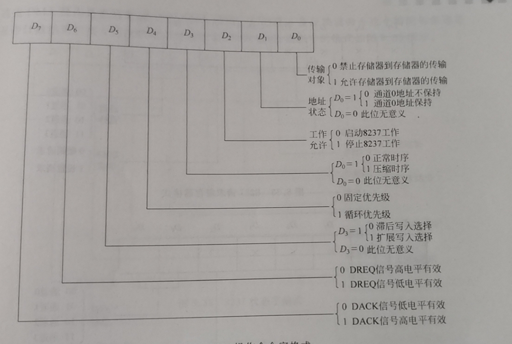
- Command register : Set up 8237A Mode of operation

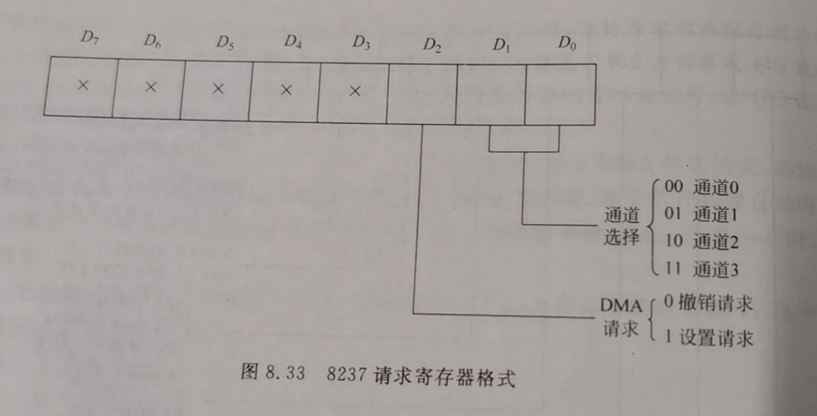
- Request register : Data block transmission can be sent by software DREQ request , Memory to memory transfer , The channel must be initiated by a software request 0.
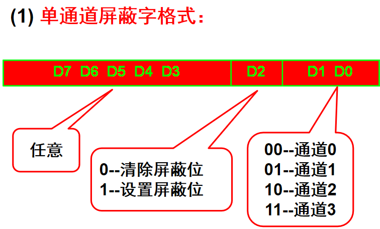
- Mask register : It is used to shield the... Sent by peripherals DREQ request .
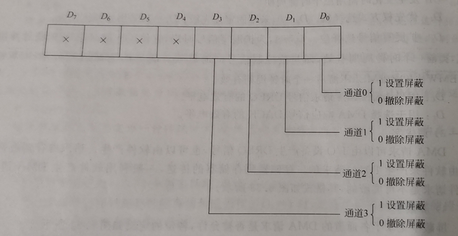
(2) Main mask word format - Status register : from CPU Read 8237A Working state of .
- Temporary register : In memory to memory transfer mode , Save the data
2.8 8237A Software commands
237A share 10 An internal register , Their operation sometimes needs cooperation 3 A software command .8237A “ Software commands ” Characteristics of :
(1) There is no need to write the control word through the data bus ;
(2) It is directly realized by address and control signal decoding .
- Clear high / Low trigger software command
high / Low trigger control 16 Read and write of bit register :
The trigger is 0, Operation low byte ;
The trigger is 1, Operation high byte ;
16 The bit register performs an operation , trigger
The status changes automatically ;
A3A2A1A0=1100, high / Low trigger reset . - Main clear command
Hardware related RESET Signals have the same function ,
A3A2A1A0=1101 - Clear mask register command
send 4 Both shielding bits are cleared ( allow DMA request )
A3A2A1A0=1110
边栏推荐
- 限时预约|6 月 Apache Pulsar 中文开发者与用户组会议
- “\“id\“ contains an invalid value“
- 【云原生 | Kubernetes篇】深入了解Deployment(八)
- Go 语言入门很简单:Go 处理 XML 文件
- wallys/IPQ8074a/2x(4 × 4 or 8 × 8) 11AX MU-MIMO DUAL CONCURRENT EMBEDDEDBOARD
- R language ggplot2 visualization: use ggplot2 visualization scatter diagram and the color parameter in AES function to specify that data points in different groups are displayed in different colors
- Speech signal processing - Fundamentals (V): Fourier transform
- redis在项目中的使用
- Our company has used this set of general solutions for 7 years, and has opened up dozens of systems, a stable batch!
- EMC surge
猜你喜欢

线下门店为什么要做新零售?

wallys/3×3 MIMO 802.11ac Mini PCIe Wi-Fi Module, QCA9880, 2,4GHz / 5GHzDesigned for Enterprise

Boost研究:Boost Log

wallys/IPQ8074a/2x(4 × 4 or 8 × 8) 11AX MU-MIMO DUAL CONCURRENT EMBEDDEDBOARD

谁还记得「张同学」?

如何使用插件化机制优雅的封装你的请求hook

STM32F407ZGT6使用SDIO方式驱动SD卡

使用深度学习进行生物网络分析

Uncover the whole link communication process of customer service im

Limited time appointment | Apache pulsar Chinese developer and user group meeting in June
随机推荐
HMS core audio editing service 3D audio technology helps create an immersive auditory feast
并行接口8255A
Speech recognition - Fundamentals (I): introduction [speech to text]
ClipboardJS——开发学习总结1
限时预约|6 月 Apache Pulsar 中文开发者与用户组会议
智慧法院新征程,无纸化办公,护航智慧法院绿色庭审
Lucene全文检索工具包学习笔记总结
koa - 洋葱模型浅析
R language ggplot2 visualization: use ggplot2 to visualize the scatter diagram and use scale_ The size function configures the measurement adjustment range of the size of the data point
Multiparty cardinality testing for threshold private set-2021: Interpretation
R语言ggplot2可视化:使用ggplot2可视化散点图、在geom_point参数中设置alpha参数指定数据点的透明度级别(points transparent、从0到1)
Paper interpretation (AGC) attributed graph clustering via adaptive graph revolution
Typescript readonlyarray (read only array type) details
1175. 质数排列
Multiparty cardinality testing for threshold private set-2021: Interpretation
"War" caused by a bottle of water
[pattern recognition]
695.最大岛屿面积
R language ggplot2 visualization: use ggplot2 to visualize the scatter diagram, and_ Set show in the point parameter_ The legend parameter is false, and the legend information is not displayed
串行通信接口8250