当前位置:网站首页>Digital IC design process summary
Digital IC design process summary
2022-07-01 01:27:00 【ty_ xiumud】
IC Design is a very complicated and long process , The author summarizes the following figure , The back end is vague , Follow up understanding and learning before supplement . According to my own understanding , Share your understanding of the design process step by step . There are inevitably problems and mistakes , I hope the students and teachers point out , thank ! BiliBili has a corresponding video , Put the video at the end of the blog post .
List of articles
IC Design flow chart
First of all, the following figure is the number summarized by the author IC Design flow chart . From design requirements to Tape-Out. The content of this picture will be described in detail below , It will be revised and corrected continuously in the future .
Design requirements
The first is requirements design , General design is nothing more than two sources , One is a new project , Demand comes from the market , Another iteration from the inheritance project . Both have product managers (IC Product Engineer ) Collect and summarize , Then give the design requirements . The design requirements here are only some technical indicators , Overall function . No code involved . Among them, the product manager needs to understand a future trend of the market , At the same time, combined with their own design ability and time , So that the designed chip is in line with the general trend of the market .
The picture below shows Mr. Zhuang PPT A picture in , Can be combined to understand .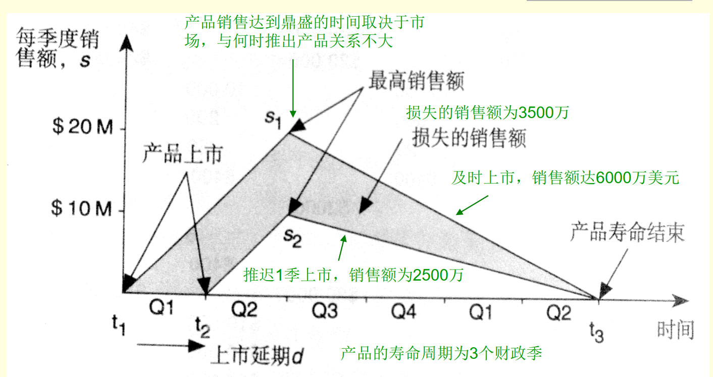
design code (Design Specification)
This design specification is generally held by engineers familiar with the project , Need to have a good understanding of the overall architecture , Module partition , Technical indicators , The implementation details need to be understood . At the same time, a non-standard design requirement is transformed into a standard design specification . This specification shall be submitted to the design engineer and the verification engineer at the same time . This leads to module level design .
IC Design Engineer
IC Design Engineer Modules that need to be designed according to their own needs , Have a detailed design in mind , Describe how your design is implemented , In fact, it is a process of sorting out your own ideas , As detailed as possible , intuitive , Describe the method of module design as concisely and clearly as possible . At the same time, start your own coding, After that, you need to write a simple testbeach To test it , Basically, there are no stupid questions for the verification engineer to verify .
IC Verification Engineer
IC Verification Engineer After getting the design specification, we need to plan a verification cycle , Extract verification points at the same time . Concept verification method , Build a verification environment , When the design engineer's code realizes certain functions, it can start verification . It's an iterative process .
Tools used
The tools used here are generally VSC+Verdi. comprehensive + Check the waveform .VIM or GVIM Text editor .SVN or Git Version management tools .
RTL level
RTL Level is the register transfer level , The commonly used language is Verilog Or is it VHDL, Most are used verilog Of . This step is also a key part , Mainly by IC Design engineer to complete , The purpose is to realize the correctness of the design function , At the same time, it can be designed comprehensively , Code readability , Low power design , Timing convergence , Processing across clock domains … In the actual project, more needs to be considered . His correctness is guaranteed by the verification engineer . from SpyGlass Of lint( Code quality ) And CDC( Cross clock domain ) To further ensure the correctness of the design .
Simply speaking , In fact, there are two things ,Timing And function.function We are inspected by the verification engineer , Therefore, the code quality is reflected in the timing , So although there is no need to do STA, But the following steps STA The result is a test of the quality of your code . Static timing analysis can only be performed at gate level , But your RTL We need to consider the results after synthesis , well RTL To synthesize a good circuit . You can't expect tools to help you synthesize extremely bad code into excellent circuits , This is unrealistic .
Logic synthesis
DC Logical synthesis is mainly about RTL Translate to gate level , Generally, this step is the boundary between the back end and the front end . What we need to do in this step is to write a design constraint . Need to consider one PAP A compromise of .power Area Performance Mainly by SDC( constraint ) To embody . No one can guarantee the design constraints here . There is no tool to guarantee , Therefore, this is a point that depends on the experience of engineers .
The following figure shows some of the work that needs to be done , The specific implementation will be carried out in the following DC A more complete introduction to . The focus here is on sorting out the process .
Consistency check
The purpose of consistency check is to check the consistency of two codes . In short, ha , It is your previous steps that ensure the correctness of your code function , But how do you know that will RTL Your function is still correct when you convert the code of level to door level ? That's what you need to use Formality To ensure the consistency of your code twice .
Gate level (STA)
It needs to be done once at the gate level Static time series analysis , It is mainly about the problems to be repaired here setup The problem of , as for hold The problem can be left to the backend to fix . The main thing is to ensure that the established time margin under the clock you need is positive .reg-in,reg-out, Whether the combinational logic is too long or not , And whether your constraints are pessimistic or optimistic , Will affect the results of your code synthesis and STA Whether to pass . The tool used is PrimeTime
DFT
Design for testability is mainly used in mass production ,ATE Self test of testing machine , The purpose is to ensure that under the premise of correct design , Problems in the manufacturing process and positioning design . Fast location problem .
Layout and wiring P&R
Including layout , Clock tree synthesis , wiring , Parameter extraction, etc , Then the post simulation . Post simulation is the simulation result with real time delay . Generally, it is very close to the real situation .
ECO
Call it engineering change order Engineer Change Order. It mainly involves minor repairs , Generally, the time is not too long , It will be over in a week , Then conduct physical verification .
Physical verification
Physical verification is mainly the inspection on the layout , Check if there is any inconsistency between your own layout and the requirements of the OEM and modify it
IC Tools used in the design process
The following picture is from teacher zhuangyiqi PPT
Numbers IC Introduction to design process
Click on Video link
边栏推荐
- [leetcode] sum of two numbers [1]
- dc_labs--lab1的学习与总结
- 【学习笔记】简单dp
- How to scroll uitableview to a specific position - how to scroll uitableview to specific position
- DC学习笔记正式篇之零——综述与基本流程介绍
- Q弹松软的大号吐司,带来更舒服的睡眠
- Basic knowledge of software and hardware -- diary (1)
- [learning notes] simple DP
- pull_ to_ refresh
- [network packet loss and network delay? This artifact can help you deal with everything!]
猜你喜欢

双位置继电器DLS-5/2 DC220V

用recyclerReview展示Banner,很简单

fluttertoast

Basic knowledge of software and hardware -- diary (1)

酒旅板块复苏,亚朵继续上市梦,距离“新住宿经济第一股“还有多远?

技术人进阶画业务大图,手把手教学来了

Impact relay zc-23/dc220v

Call the classic architecture and build the model based on the classic

Dls-20 double position relay 220VDC
![奇偶链表[链表操作的两种大方向]](/img/4e/ce860bc172bb75f456427ba26a7842.png)
奇偶链表[链表操作的两种大方向]
随机推荐
双位置继电器ST2-2L/AC220V
Service grid ASM year end summary: how do end users use the service grid?
How to do the performance pressure test of "Health Code"
Installing mongodb database in Windows Environment
The liquor and tourism sector recovers, and Yaduo continues to dream of listing. How far is it from "the first share of the new accommodation economy"?
K210工地安全帽
System.CommandLine版CSRebot
fluttertoast
Docker deployment MySQL 8
Q play soft large toast to bring more comfortable sleep
系统设置大页
用Steam教育启发学生多元化思维
[learning notes] structure
Poor students can also play raspberry pie
Exploring the road of steam education innovation in the Internet Era
uniapp官方组件点击item无效,解决方案
Basic knowledge of software and hardware -- diary (1)
Typora的使用
visual studio 2019 快捷键备忘
Analyzing the wisdom principle in maker education practice