当前位置:网站首页>RK3566调试GC2053
RK3566调试GC2053
2022-06-21 16:57:00 【火柴棍mcu】
电路
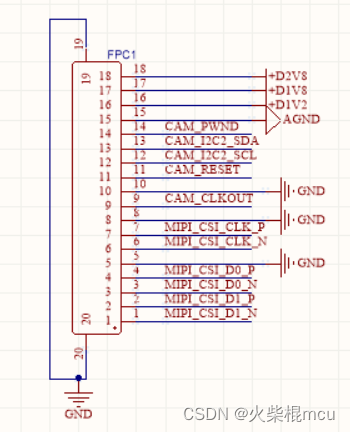
RK3566主板外接了一个MIPI接口涉嫌头模组,I2C接口I2C2,模组Sensor为GC2053,模组的设备地址为0x37(地址需和模组厂家确定),电路如下:
调试
DTS文件加入GC2053的配置
i2c节点下加入gc2053节点:
	gc2053: [email protected] {
		status = "okay";
		compatible = "galaxycore,gc2053";
		reg = <0x37>;

		power-domains = <&power RK3568_PD_VI>;

		clocks = <&cru CLK_CAM0_OUT>;
		clock-names = "xvclk";

		pinctrl-names = "rockchip,camera_default", "rockchip,camera_sleep";
		pinctrl-0 = <&cam_clkout0>;
		pinctrl-1 = <&cam_sleep>;
		reset-gpios = <&gpio0 16 GPIO_ACTIVE_LOW>;
		pwdn-gpios = <&gpio0 17 GPIO_ACTIVE_LOW>;

		//reset pin control by hardware,used this pin switch to mipi input
		//1->2LANE(LANE 0&1) FRONT camera, 0->4LANE REAR camera
		rockchip,camera-module-index = <0>;
		rockchip,camera-module-facing = "front";
		rockchip,camera-module-name = "YT-RV1109-2-V1";
		rockchip,camera-module-lens-name = "40IR-2MP-F20";
		port {
			gc2053_out: endpoint {
				remote-endpoint = <&mipi_in_ucam0>;
				data-lanes = <1 2>;
			};
		};
	};
节点pinctrl下增加cam节点:
	cam {
		cam_clkout0: cam-clkout0 {
			rockchip,pins =
				/* cam_clkout0 */
				<4 RK_PA7 1 &pcfg_pull_none>;
		};

		cam_sleep: cam-sleep {
			rockchip,pins =
				/* cam_sleep */
				<0 RK_PC1 RK_FUNC_GPIO &pcfg_pull_none>;
		};

		camera_rst: camera-rst {
			rockchip,pins =
				/* front camera reset */
				<0 RK_PC0 RK_FUNC_GPIO &pcfg_output_high_pull_none>;
		};

	};
内核加入对GC2053的支持
使用PWM产生8Mhz的clk
[[email protected]:/sys/devices/platform/fe6e0000.pwm/pwm/pwmchip0/pwm0]# i2cdetect -y
 2
     0  1  2  3  4  5  6  7  8  9  a  b  c  d  e  f
00:                         -- -- -- -- -- -- -- --
10: -- -- -- -- -- -- -- -- -- -- -- -- -- -- -- --
20: -- -- -- -- -- -- -- -- -- -- -- -- -- -- -- --
30: -- -- -- -- -- -- -- -- -- -- -- -- -- -- -- --
40: -- -- -- -- -- -- -- -- -- -- -- -- -- -- -- --
50: 50 -- -- -- -- -- -- -- -- -- -- -- -- -- -- --
60: -- -- -- -- -- -- -- -- -- -- -- -- -- -- -- --
70: -- -- -- -- -- -- -- --
[[email protected]:/sys/devices/platform/fe6e0000.pwm/pwm/pwmchip0/pwm0]# echo 0 > ena
ble
[[email protected]:/sys/devices/platform/fe6e0000.pwm/pwm/pwmchip0/pwm0]# echo 63 > du
ty_cycle
[[email protected]:/sys/devices/platform/fe6e0000.pwm/pwm/pwmchip0/pwm0]# echo 125 > p
eriod
[[email protected]:/sys/devices/platform/fe6e0000.pwm/pwm/pwmchip0/pwm0]# echo 1 > ena
ble
[[email protected]:/sys/devices/platform/fe6e0000.pwm/pwm/pwmchip0/pwm0]# i2cdetect -y
 2
     0  1  2  3  4  5  6  7  8  9  a  b  c  d  e  f
00:                         -- -- -- -- -- -- -- --
10: -- -- -- -- -- -- -- -- -- -- -- -- -- -- -- --
20: -- -- -- -- -- -- -- -- -- -- -- -- -- -- -- --
30: -- -- -- -- -- -- -- 37 -- -- -- -- -- -- -- --
40: -- -- -- -- -- -- -- -- -- -- -- -- -- -- -- --
50: 50 -- -- -- -- -- -- -- -- -- -- -- -- -- -- --
60: -- -- -- -- -- -- -- -- -- -- -- -- -- -- -- --
70: -- -- -- -- -- -- -- --
此时可以看到i2c2总线上有从地址为0x37的设备了;
[[email protected]:/]# cat /sys/kernel/debug/clk/clk_summary
                                 enable  prepare  protect                                duty
   clock                          count    count    count        rate   accuracy phase  cycle
---------------------------------------------------------------------------------------------
 rk808-clkout2                        0        0        0       32768          0     0  50000
 rk808-clkout1                        0        0        0       32768          0     0  50000
 clk_scmi_ddr                         0        0        0   324000000          0     0  50000
 clk_scmi_npu                         0        0        0   594000000          0     0  50000
 clk_scmi_gpu                         0        2        0   198000000          0     0  50000
 clk_scmi_cpu                         0        0        0  1416000000          0     0  50000
 xin32k                               0        0        0       32768          0     0  50000
 xin24m                              22       24        0    24000000          0     0  50000
    clk_cpu_boost                     0        0        0    24000000          0     0  50000
    clk_optc_arb                      1        1        0    24000000          0     0  50000
    clk_timer5                        0        0        0    24000000          0     0  50000
    clk_timer4                        0        0        0    24000000          0     0  50000
    clk_timer3                        0        0        0    24000000          0     0  50000
    clk_timer2                        0        0        0    24000000          0     0  50000
    clk_timer1                        0        0        0    24000000          0     0  50000
    clk_timer0                        1        1        0    24000000          0     0  50000
    dbclk_gpio                        0        0        0    24000000          0     0  50000
       dbclk_gpio4                    0        0        0    24000000          0     0  50000
       dbclk_gpio3                    0        0        0    24000000          0     0  50000
       dbclk_gpio2                    0        0        0    24000000          0     0  50000
       dbclk_gpio1                    0        0        0    24000000          0     0  50000
    clk_pwm3_capture                  0        0        0    24000000          0     0  50000
    clk_pwm3                          0        0        0    24000000          0     0  50000
    clk_pwm2_capture                  0        0        0    24000000          0     0  50000
    clk_pwm2                          1        1        0    24000000          0     0  50000
    clk_pwm1_capture                  0        0        0    24000000          0     0  50000
    clk_pwm1                          1        2        0    24000000          0     0  50000
    clk_i2c                           0        3        0    24000000          0     0  50000
       clk_i2c5                       0        0        0    24000000          0     0  50000
       clk_i2c4                       0        1        0    24000000          0     0  50000
       clk_i2c3                       0        1        0    24000000          0     0  50000
       clk_i2c2                       0        1        0    24000000          0     0  50000
       clk_i2c1                       0        0        0    24000000          0     0  50000
    sclk_uart9_mux                    0        0        0    24000000          0     0  50000
       sclk_uart9                     0        0        0    24000000          0     0  50000
    sclk_uart8_mux                    0        0        0    24000000          0     0  50000
       sclk_uart8                     0        0        0    24000000          0     0  50000
    sclk_uart7_mux                    0        0        0    24000000          0     0  50000
       sclk_uart7                     0        0        0    24000000          0     0  50000
    sclk_uart6_mux                    0        0        0    24000000          0     0  50000
       sclk_uart6                     0        0        0    24000000          0     0  50000
    sclk_uart5_mux                    0        0        0    24000000          0     0  50000
       sclk_uart5                     0        0        0    24000000          0     0  50000
    sclk_uart4_mux                    0        0        0    24000000          0     0  50000
       sclk_uart4                     0        0        0    24000000          0     0  50000
    sclk_uart3_mux                    0        0        0    24000000          0     0  50000
       sclk_uart3                     0        0        0    24000000          0     0  50000
    sclk_uart2_mux                    1        1        0    24000000          0     0  50000
       sclk_uart2                     1        1        0    24000000          0     0  50000
    sclk_uart1_mux                    0        0        0    24000000          0     0  50000
       sclk_uart1                     0        0        0    24000000          0     0  50000
    tclk_wdt_ns                       1        1        0    24000000          0     0  50000
    clk_saradc                        1        1        0    24000000          0     0  50000
    clk_hdmi_sfr                      0        0        0    24000000          0     0  50000
    clk_vop_pwm                       0        0        0    24000000          0     0  50000
    clk_cam1_out                      0        0        0    24000000          0     0  50000
    clk_cif_out                       0        0        0    24000000          0     0  50000
GRF_GPIO4A_IOMUX_H
Address: Operational Base + offset (0x0064)
| 31:16 | RW | 0x0000 | write_enable Write enable for lower 16bits, each bit is individual. 1'b0: Write access disable 1'b1: Write access enable |
| 15 | RO | 0x0 | reserved |
| 14:12 | RW | 0x0 | gpio4a7_sel 3'h0: GPIO4_A7 3'h1: CAM_CLKOUT0 3'h2: EBC_SDCE1 3'h3: GMAC1_RXD0M1 3'h4: SPI3_CS1M0 3'h5: I2S1_LRCKRXM1 |
查询IO寄存器:
SYS_GRF 0xFDC60000
GRF_GPIO4A_IOMUX_L 0x0060
GRF_GPIO4A_IOMUX_H 0x0064
[[email protected]:/sys/kernel/debug/clk/clk_cam0_out]# io -4 -l 0x8 0xFDC60060
fdc60060:  00000000 00001000

[[email protected]:/]# io -4 -w 0xFDC60064 0x10001000
[[email protected]:/]# io -4 -l 0x8 0xFDC60060
fdc60060:  00004400 00001000
bit[14:12]=001; GPIO4A7选择CAM_CLK_OUT0功能;
CRU_S 0xFDD10000
CRU_CLKSEL_CON35
Address: Operational Base + offset (0x018C)
| 31:16 | RW | 0x0000 | write_enable Write enable for lower 16 bits, each bit is individual. 1'b0: Write access disable 1'b1: Write access enable |
| 15:14 | RW | 0x3 | clk_cif_out_sel clk_cif_out clock mux. 2'b00: clk_gpll_mux 2'b01: usbphy480m_mux 2'b10: xin_osc0_func_mux |
| 13:8 | RW | 0x00 | clk_cif_out_div Divide clk_cif_out by (div_con + 1) |
| 7:6 | RW | 0x0 | clk_isp_sel clk_isp clock mux. 2'b00: clk_cpll_mux 2'b01: clk_gpll_mux 2'b10: clk_hpll_mux |
| 5 | RO | 0x0 | reserved |
| 4:0 | RW | 0x01 | clk_isp_div Divide clk_isp by (div_con + 1) |
CRU_CLKSEL_CON36
Address: Operational Base + offset (0x0190)
| 31:16 | RW | 0x0000 | write_enable Write enable for lower 16 bits, each bit is individual. 1'b0: Write access disable 1'b1: Write access enable |
| 15:14 | RW | 0x3 | clk_cam1_out_sel clk_cam1_out clock mux. 2'b00: clk_gpll_mux 2'b01: usbphy480m_mux 2'b10: xin_osc0_func_mux |
| 13:8 | RW | 0x00 | clk_cam1_out_div Divide clk_cam1_out by (div_con + 1) |
| 7:6 | RW | 0x3 | clk_cam0_out_sel clk_cam0_out clock mux. 2'b00: clk_gpll_mux 2'b01: usbphy480m_mux 2'b10: xin_osc0_func_mux |
| 5:0 | RW | 0x00 | clk_cam0_out_div Divide clk_cam0_out by (div_con + 1) |
CRU_GATE_CON19
Address: Operational Base + offset (0x034C)
| 31:16 | RW | 0x0000 | write_enable Write enable for lower 16 bits, each bit is individual. 1'b0: Write access disable 1'b1: Write access enable |
| 15:11 | RO | 0x00 | reserved |
| 10 | RW | 0x0 | clk_cam1_out_en clk_cam1_out clock gating control. When high, disable clock |
| 9 | RW | 0x0 | clk_cam0_out_en clk_cam0_out clock gating control. When high, disable clock |
| 8 | RW | 0x0 | clk_cif_out_en clk_cif_out clock gating control. When high, disable clock |
| 7:5 | RO | 0x0 | reserved |
| 4 | RW | 0x0 | pclk_csi2host1_en pclk_csi2host1 clock gating control. When high, disable clock |
| 3 | RO | 0x0 | reserved |
| 2 | RW | 0x0 | clk_isp_en clk_isp clock gating control. When high, disable clock |
| 1 | RW | 0x0 | hclk_isp_en hclk_isp clock gating control. When high, disable clock |
| 0 | RW | 0x0 | aclk_isp_en aclk_isp clock gating control. When high, disable clock |
以上内容参考文档<Rockchip RK3568 TRM Part1 V1.1-20210301.pdf>
cam的时钟来自于GPLL
| GPLL | 提供总线、外 设时钟做备份 | 一般设置在 594M 或者 1200M,保证基本的 100、200、300、400M 的时钟都有输出 |
以上内容参考文档<Rockchip_Developer_Guide_Linux4.4_4.19_Clock_CN.pdf>
static struct rockchip_clk_branch rk3568_clk_branches[] __initdata = {
...
/* PD_VI */
COMPOSITE(CLK_CIF_OUT, "clk_cif_out", gpll_usb480m_xin24m_p, 0,
RK3568_CLKSEL_CON(35), 14, 2, MFLAGS, 8, 6, DFLAGS,
RK3568_CLKGATE_CON(19), 8, GFLAGS),
COMPOSITE(CLK_CAM0_OUT, "clk_cam0_out", gpll_usb480m_xin24m_p, 0,
RK3568_CLKSEL_CON(36), 6, 2, MFLAGS, 0, 6, DFLAGS,
RK3568_CLKGATE_CON(19), 9, GFLAGS),
COMPOSITE(CLK_CAM1_OUT, "clk_cam1_out", gpll_usb480m_xin24m_p, 0,
RK3568_CLKSEL_CON(36), 14, 2, MFLAGS, 8, 6, DFLAGS,
RK3568_CLKGATE_CON(19), 10, GFLAGS),
}
clk_set_rate(struct clk *clk, unsigned long rate)分析:
..\kernel\drivers\clk\clk.c中
int clk_set_rate(struct clk *clk, unsigned long rate)
{
	int ret;

	if (!clk)
		return 0;

	/* prevent racing with updates to the clock topology */
	clk_prepare_lock();

	if (clk->exclusive_count)
		clk_core_rate_unprotect(clk->core);

	ret = clk_core_set_rate_nolock(clk->core, rate);

	if (clk->exclusive_count)
		clk_core_rate_protect(clk->core);

	clk_prepare_unlock();

	return ret;
}
static int clk_core_set_rate_nolock(struct clk_core *core,
unsigned long req_rate)
{
struct clk_core *top, *fail_clk;
unsigned long rate;
int ret = 0;
/*
* The prepare lock ensures mutual exclusion with other tasks.
* set_rate_nesting_count is a static so that it can be incremented in
* the case of reentrancy caused by a set_rate() ops callback itself
* calling clk_set_rate(). That way, the voltage level votes for the
* old rates are safely removed when the original invocation of this
* function completes.
*/
static unsigned int set_rate_nesting_count;
if (!core)
return 0;
rate = clk_core_req_round_rate_nolock(core, req_rate);
/* bail early if nothing to do */
if (rate == clk_core_get_rate_nolock(core))
return 0;
/* fail on a direct rate set of a protected provider */
if (clk_core_rate_is_protected(core))
return -EBUSY;
set_rate_nesting_count++;
/* calculate new rates and get the topmost changed clock */
top = clk_calc_new_rates(core, req_rate);
if (!top) {
ret = -EINVAL;
goto pre_rate_change_err;
}
ret = clk_pm_runtime_get(core);
if (ret)
goto pre_rate_change_err;
/* notify that we are about to change rates */
fail_clk = clk_propagate_rate_change(top, PRE_RATE_CHANGE);
if (fail_clk) {
pr_debug("%s: failed to set %s clock to run at %lu\n", __func__,
fail_clk->name, req_rate);
clk_propagate_rate_change(top, ABORT_RATE_CHANGE);
ret = -EBUSY;
clk_pm_runtime_put(core);
goto pre_rate_change_err;
}
core->req_rate = req_rate;
/* change the rates */
ret = clk_change_rate(top);
set_rate_nesting_count--;
if (ret) {
pr_err("%s: failed to set %s clock to run at %lu\n", __func__,
top->name, req_rate);
clk_propagate_rate_change(top, ABORT_RATE_CHANGE);
clk_vote_safe_vdd();
goto post_rate_change_err;
}
post_rate_change_err:
/*
* Only remove vdd_class level votes for old clock rates after all
* nested clk_set_rate() calls have completed.
*/
if (set_rate_nesting_count == 0) {
ret |= clk_unvote_old_rate_vdd();
clk_cleanup_vdd_votes();
}
clk_pm_runtime_put(core);
return ret;
pre_rate_change_err:
set_rate_nesting_count--;
if (set_rate_nesting_count == 0) {
clk_unvote_new_rate_vdd();
clk_cleanup_vdd_votes();
}
return ret;
}
[[email protected]:/]# cat /sys/kernel/debug/clk/clk_summary
                                 enable  prepare  protect                                duty
   clock                          count    count    count        rate   accuracy phase  cycle
---------------------------------------------------------------------------------------------
    xin_osc0_usbphy0_g                1        1        0    24000000          0     0  50000
       clk_usbphy0_ref                2        2        0    24000000          0     0  50000
          usb480m_phy                 2        2        0   480000000          0     0  50000
             usb480m                  1        1        0   480000000          0     0  50000
clk_cam0_out 2 2 0 24000000 0 0 50000[[email protected]:/]# cd /sys/kernel/debug/pm_genpd/
[[email protected]:/sys/kernel/debug/pm_genpd]# ls
pd_gpu pd_pipe pd_rkvdec pd_vi pd_vpu
pd_npu pd_rga pd_rkvenc pd_vo pm_genpd_summary
[[email protected]:/sys/kernel/debug/pm_genpd]# cd pd_vi/
[[email protected]:/sys/kernel/debug/pm_genpd/pd_vi]# cat current_state
off-0查看PD_VI日志
[[email protected]:/sys/kernel/debug/pm_genpd/pd_vo]# dmesg | grep pd_vi
[    0.439066] rockchip-pm-domain fdd90000.power-management:power-controller: Looking up pd_vi-supply from device tree
[    0.439081] rockchip-pm-domain fdd90000.power-management:power-controller: Looking up pd_vi-supply property in node /[email protected]/power-controller failed
使用有源晶振给Sensor提供时钟,再次调试
使用一颗24MHz的有源时钟给Sensor的MCLK管脚提供24MHz的时钟,有源晶振的电源使用1.8V供电。
设备启动完成后,通过i2c-tool工具查看i2c2总线上是否有0x37的设备:
[[email protected]:/]# i2cdetect -y 2
     0  1  2  3  4  5  6  7  8  9  a  b  c  d  e  f
00:                         -- -- -- -- -- -- -- --
10: -- -- -- -- -- -- -- -- -- -- -- -- -- -- -- --
20: -- -- -- -- -- -- -- -- -- UU -- -- -- -- -- --
30: -- -- -- -- -- -- -- 37 -- -- -- -- -- -- -- --
40: -- -- -- -- -- -- -- -- -- -- -- -- -- -- -- --
50: 50 -- -- -- -- -- -- -- -- -- -- -- -- -- -- --
60: -- -- -- -- -- -- -- -- -- -- -- -- -- -- -- --
70: -- -- -- -- -- -- -- --
可以看到总线上有0x37的设备,但是设备没加入驱动中。
通过i2cget命令读取0xF0和0小F1寄存器获取gc2053的CHIP ID:
[[email protected]:/]# i2cget -f -y 2 0x37 0xF0
0x20
[[email protected]:/]# i2cget -f -y 2 0x37 0xF1
0x53
查看开机日志,确认gc2053的驱动是否加载成功:
[[email protected]:/]# dmesg | grep gc
[    0.000000] Linux version 4.19.193 ([email protected]) (gcc version 6.3.1 20170404 (Linaro GCC 6.3-2017.05), GNU ld (Linaro_Binutils-2017.05) 2.27.0.20161019) #31 SMP Mon Jun 13 11:56:01 CST 2022
[    1.019617] gc2053 2-0037: driver version: 00.01.01
[    1.019718] gc2053 2-0037: Failed to get power-gpios
[    1.019740] gc2053 2-0037: Looking up dovdd-supply from device tree
[    1.019751] gc2053 2-0037: Looking up dovdd-supply property in node /[email protected]/[email protected] failed
[    1.019778] gc2053 2-0037: 2-0037 supply dovdd not found, using dummy regulator
[    1.019872] gc2053 2-0037: Linked as a consumer to regulator.0
[    1.019890] gc2053 2-0037: Looking up avdd-supply from device tree
[    1.019898] gc2053 2-0037: Looking up avdd-supply property in node /[email protected]/[email protected] failed
[    1.019912] gc2053 2-0037: 2-0037 supply avdd not found, using dummy regulator
[    1.019964] gc2053 2-0037: Looking up dvdd-supply from device tree
[    1.019973] gc2053 2-0037: Looking up dvdd-supply property in node /[email protected]/[email protected] failed
[    1.019985] gc2053 2-0037: 2-0037 supply dvdd not found, using dummy regulator
[    1.020037] gc2053 2-0037: lane_num(2)  pixel_rate(118800000)
[    1.025878] gc2053 2-0037: gc2053 read reg(0xf0 val:0x0) failed !
[    1.026089] gc2053 2-0037: gc2053 read reg(0xf1 val:0x0) failed !
[    1.026107] gc2053 2-0037: gc2053_read_reg failed (-6)
通过日志得知,gc2053的驱动加载失败了。
断电后立即上电,再查看开机日志,确认gc2053的驱动是否加载成功:
[[email protected]:/]# dmesg | grep gc2053
[    1.021564] gc2053 2-0037: driver version: 00.01.01
[    1.021704] gc2053 2-0037: Failed to get power-gpios
[    1.021726] gc2053 2-0037: Looking up dovdd-supply from device tree
[    1.021737] gc2053 2-0037: Looking up dovdd-supply property in node /[email protected]/[email protected] failed
[    1.021764] gc2053 2-0037: 2-0037 supply dovdd not found, using dummy regulator
[    1.021847] gc2053 2-0037: Linked as a consumer to regulator.0
[    1.021863] gc2053 2-0037: Looking up avdd-supply from device tree
[    1.021872] gc2053 2-0037: Looking up avdd-supply property in node /[email protected]/[email protected] failed
[    1.021884] gc2053 2-0037: 2-0037 supply avdd not found, using dummy regulator
[    1.021933] gc2053 2-0037: Looking up dvdd-supply from device tree
[    1.021942] gc2053 2-0037: Looking up dvdd-supply property in node /[email protected]/[email protected] failed
[    1.021953] gc2053 2-0037: 2-0037 supply dvdd not found, using dummy regulator
[    1.022024] gc2053 2-0037: lane_num(2)  pixel_rate(118800000)
[    1.030406] gc2053 2-0037: Detected GC2053 sensor
[    1.030477] rockchip-csi2-dphy csi2-dphy0: dphy0 matches m00_f_gc2053 2-0037:bus type 4
这一次驱动加载成功了,可能是由于有源晶振冷启动时间比较长,加载驱动时,还没有产生时钟。
显示拓扑结构
执行media-ctl -p -d /dev/media0命令:
[[email protected]:/]# media-ctl -p -d /dev/media0
- entity 67: rockchip-csi2-dphy0 (2 pads, 2 links)
             type V4L2 subdev subtype Unknown flags 0
             device node name /dev/v4l-subdev2
        pad0: Sink
                [fmt:SGRBG10_1X10/[email protected]/300000 field:none]
                <- "m00_f_gc2053 2-0037":0 [ENABLED]
        pad1: Source
                [fmt:SGRBG10_1X10/[email protected]/300000 field:none]
                -> "rkisp-csi-subdev":0 [ENABLED]

- entity 70: m00_f_gc2053 2-0037 (1 pad, 1 link)
             type V4L2 subdev subtype Sensor flags 0
             device node name /dev/v4l-subdev3
        pad0: Source
                [fmt:SGRBG10_1X10/[email protected]/300000 field:none]
                -> "rockchip-csi2-dphy0":0 [ENABLED]
拍摄图像
设备接上显示屏及触屏再次启动设备,开机后点击桌面的qcamera进去相机程序,并且摄像头正常的话可以显示图像:
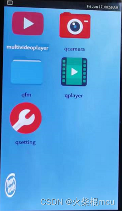

不过运行了30分钟后,就没有图像输出了,重新上电也没有图像输出了,可能是sensor太热不工作了。
查找问题
在qcamera运行时,通过示波器可以测量到CAM_CLKOUT0(GPIO4_A7)产生了24MHz的时钟,通过此现象可知CAM_CLKOUT0可以产生时钟,可能是驱动在读取sensor id时没有CAM_CLKOUT0没有产生时钟,导致驱动读取sensor id失败,驱动加载失败。
按照官方<Rockchip_Trouble_Shooting_Linux4.4_Camera_CN.pdf>文档所述,可以将驱动中的 power_off() 函数的实现注释掉,这样mclk可一直产生。
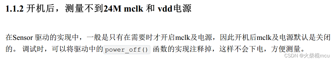
在gc2053的驱动中注释了__gc2053_power_off的实现,但是qcamera退出后CAM_CLKOUT0任然没有产生24MHz的时钟了,所以官方的文档的这一点的描述还需视其它情况而定。
static void __gc2053_power_off(struct gc2053 *gc2053)
{
/*
	int ret;
	struct device *dev = &gc2053->client->dev;

	if (!IS_ERR(gc2053->pwdn_gpio))
		gpiod_set_value_cansleep(gc2053->pwdn_gpio, 1);
	clk_disable_unprepare(gc2053->xvclk);

	if (!IS_ERR(gc2053->reset_gpio))
		gpiod_set_value_cansleep(gc2053->reset_gpio, 1);

	if (!IS_ERR_OR_NULL(gc2053->pins_sleep)) {
		ret = pinctrl_select_state(gc2053->pinctrl,
					   gc2053->pins_sleep);
		if (ret < 0)
			dev_dbg(dev, "could not set pins\n");
	}
	if (!IS_ERR(gc2053->power_gpio))
		gpiod_set_value_cansleep(gc2053->power_gpio, 0);
	regulator_bulk_disable(GC2053_NUM_SUPPLIES, gc2053->supplies);
*/
}边栏推荐
- 泰克示波器TCP202电流探头的使用说明
- 【微服务|Nacos】快速实现nacos的配置中心功能,并完成配置更新和版本迭代
- EtherCAT igh function attempt
- Node的url模块
- About the basic operation of xlrd Library (for beginners)
- LeetCode 1108 IP地址无效化[暴力] HERODING的LeetCode之路
- 论文笔记 ACL 2022|Unified Structure Generation for Universal Information Extraction
- Tcpserver enable multithreading
- EtherCAT igh源码的ecrt_slave_config_dc()函数的理解。
- What is the S3 protocol that we are talking about every day? This article takes you to understand the story behind S3
猜你喜欢
是关于Linux中一步建立yum源缓存问题

EtherCAT igh主站控制3个台达asdaa2伺服转圈圈

Laravel实现软删除

Node输出方式

Vit is crazy, 10+ visual transformer model details

SQL操作:WITH表达式及其应用

Development of digital collection system and construction of NFT artwork trading platform

Paper notes ACL 2022 unified structure generation for universal information extraction
Tcpserver enable multithreading

EtherCAT igh 'Fatal Sync Error'——0x002C,0x001A
随机推荐
【微服务|Nacos】Nacos实现分布式配置中心进阶版
Reids面试题集合 数据结构+穿透雪崩+持久化+内存淘汰策略+数据库双写+哨兵
Redis配置与优化
Win32com operation Excel
POSIX创建终止线程
使用tidevice启动WDA
Typescript的通用类型检查
小程序的宿主环境、组件、API、协同工作和发布
搜索(集训)
PHP输出函数
EtherCAT igh 'Fatal Sync Error'——0x002C,0x001A
有了mitmdump还不赶紧扔掉Charles
Node的json解析
大型网站技术架构 | 信息加密技术及密匙安全管理
数字藏品系统开发,NFT艺术品交易平台搭建
2022 high altitude installation, maintenance and removal work license question bank and simulated examination
PHP连接Mysql8.0报错:Illuminate\Database\QueryException
About the basic operation of xlrd Library (for beginners)
Move Protocol Beta测试版稳定,临时决定奖池规模再扩大
Deeply understand the attention mechanism of map