当前位置:网站首页>Graduation design of fire hydrant monitoring system --- thesis (add the most comprehensive hardware circuit design - > driver design - > Alibaba cloud Internet of things construction - > Android App D
Graduation design of fire hydrant monitoring system --- thesis (add the most comprehensive hardware circuit design - > driver design - > Alibaba cloud Internet of things construction - > Android App D
2022-06-12 02:15:00 【Dengjiawen 007】
Design presentation video connection : Fire hydrant monitoring system video Driver project file : Fire hydrant monitoring system driver engineering All design data of fire hydrant monitoring system : Full stack design , As shown in the figure below 
The good news : Pay attention to the students who add collections and comments , There is a chance to get a piece of circuit board for the graduation project ( The rules : After following the collection , Comment on the first place in the comment area 、 Eighteenth place 、 The 36th place can get the circuit board , Be careful “ Cash on Delivery , No postage is included in the small edition ”)

I'm sorry : Papers are moving to CSDN in , The mathematical formula of the article has some deformation , You can download the papers uploaded by the editor to view , There are also some circuit screenshots in the paper that have not been modified , You can download the project files I uploaded and check them ! Be careful : This graduation project is for your reference , Without my permission , No forwarding and related business activities .
key word : The Internet of things ; Smart city ; Fire hydrant monitoring system ; Solar charging
Catalog
- 1 front said
- 2 Fire hydrant monitoring system design
- 3 Hardware design of fire hydrant monitoring system
- 4 Software design of fire hydrant monitoring system
- 4.1.1 General idea of overall software system design
- 5 Fire hydrant monitoring system test
- 5.1 SWD Interface burning program test
- 5.2 USB Interface burning program test
- 5.3 Fire hydrant monitoring system power on and start test
- 5.4 Cloud intelligence APP Wireless remote observation and control equipment test
- 5.5 bluetooth APP Wireless short-range observation and control equipment test
- 5.7 Three input power tests
- 6 summary
1 front said
1.1 The research background of this project is
Since the reform and development 30 Over the years , China's economy and science and technology have developed rapidly , Furthermore, the quality of life of the common people has been continuously improved . And all kinds of consumer products of these wireless Internet of things technologies have also penetrated into people's daily life , It makes people rely on the intelligent products of the Internet of things and have higher demands on their quality and functions , Therefore, wireless IOT devices like some new intelligent monitoring systems are being built in smart cities 、 Smart farms are highly valued by relevant governments and enterprises .
In the last decade , The scale of urbanization in China continues to expand , Various public facilities in people's living environment are also covered on a larger scale . Although people have improved their quality of life , But it also brings a lot of troubles , Because it is frequently reported in the news that the best fire fighting time is missed due to the failure of fire hydrants in a community . It can be seen from these relevant news reports , The residential areas in the city are densely populated , The improvement of the quality of life has led to the use of a variety of smart devices , The use of non-standard equipment will cause a fire , Because of the large number and complex distribution of fire hydrants, it is difficult to supervise and maintain , Once the fire hydrant is damaged 、 There is no water inside 、 Internal undervoltage 、 Illegal water theft and other incidents cannot be maintained and repaired in time , This led to the tragedy that the fire hydrant on the news could not play its fire-fighting function . From the above conclusions, it can be concluded that the fire hydrant monitoring system equipment can solve the difficulties of fire hydrant equipment monitoring and maintenance .
In recent news reports, it was reported that there was a shortage of electricity in northern China , With the development of economy and the progress of science and Technology , Electricity has become an indispensable energy in all fields of human society . Therefore, this monitoring system equipment can not just realize the functions of unmanned remote monitoring and so on , It is also necessary to reduce energy consumption and use renewable energy to maintain equipment operation in terms of ensuring equipment reliability .
1.2 Development status at home and abroad
Traditional fire hydrants do not have any electronic equipment attached , The maintenance personnel of relevant departments shall regularly inspect and maintain the equipment , As a result, once the fire hydrant equipment is damaged, it may not be repaired for a long time , This greatly increases the security risks in people's lives , And it consumes a lot of manpower on the maintenance cost .
stay 90 years , Monitoring system technology has been studied abroad . The monitoring system starts from the original manual on-site monitoring mode , It has gradually developed into a monitoring system based on sensors and networks , It is also slowly divorced from human resources , Further realize intelligent and commercialized modes . Use the analog instrument cluster to collect information and execute instructions 、 Record and control . These monitoring system devices use sensors to detect and collect gases that human beings can perceive and cannot perceive 、 Liquid 、 Solid and other data , Then perform corresponding actions for data analysis . And in this age of intelligence , The core of intelligent monitoring equipment is processor , That's the sensor .
In the history of sensors , The research and development of sensors is relatively late in China . Because of the blockade of foreign countries on China's sensor technology , Therefore, our country has encountered difficulties in the research and development of sensors , Even if the developed sensor has a large gap with the international standard in technology . According to the relevant data analysis on the Internet and books , Our country is developing sensor technology 、 It is beautiful in terms of technology 、 Virtue 、 Japan 、 There is still a big gap between Korea and other industrialized countries . What is shocking is , beautiful 、 Virtue 、 The sensor industry of these three countries in Japan accounts for about% of the global market 70%, However, the demand for sensors in China is one of the highest in the world , Every year, a large number of sensors are imported from abroad .
Because sensors are used in industry 、 Automobile and other intelligent devices play an important role , Every country also pays more and more attention to sensors . With the United States 、 Japan 、 South Korea, Germany and other technologically developed countries , China is facing three great challenges in the sensor industry :
First of all , R & D capability of products with independent intellectual property rights or relatively new products , Are relatively poor ; Because the sensor design has strict requirements for sensitivity and accuracy , However, it is difficult for China to meet the international requirements in the research and development of sensors , Therefore, more than 90% of domestic medium and high-grade sensor products are imported from abroad . Because most of the medium and high-grade sensors in China are imported from foreign countries , The sensor industry in China has been in the “ To be led by the nose ” The state of .
second , There is no exact standard for sensor research and development in China , Fuzzy standards make it impossible to unify the research and development of sensors , As a result, the sensors produced are miscellaneous 、 Not to stick to one pattern . Not only is the standard vague in sensor research and development , And our country does not pay enough attention to talent training , Leading to brain drain and lack of core technology , Only then further causes the domestic sensor market to be difficult to expand , There is a long-term state of being suppressed by the foreign sensor market .
Third , The distribution of enterprises in most parts of China is not only disorderly , And most of the domestic enterprises are small and medium-sized enterprises , However, these small and medium-sized enterprises in terms of capital 、 technical 、 Structural management is relatively weak 、 What is lacking , As a result, the overall comprehensive capacity of domestic enterprises has been pulled down .
Although China is much weaker than those developed countries in terms of sensor R & D technology , However, some developed countries are weak in the field of communication due to lack of funds , For example, Japan 、 South Korea , As a result, these developed countries cannot develop large-scale smart Internet of things like China , The United States is a vast country with few people , The US government's investment in the Internet of things and the military , Both are more willing to invest more in the military , This makes it impossible for developed countries like this to develop the smart Internet of things on a large scale .
Because China has invested heavily in the development of the smart IOT , Therefore, there have been many breakthroughs in the research and development of sensors . Equipment such as fire hydrant monitoring system also gets dividends from it , The cost of using domestic sensors is low , Reliable performance .
1.3 The purpose and significance of the research
From the current situation , In most cities and other areas of China, there are some major deficiencies in the monitoring and maintenance management of fire hydrant equipment , So there are many fire safety hazards in these areas . The fire hydrant monitoring system can realize remote monitoring and alarm , The consumption of manpower is greatly reduced . The fire hydrant monitoring system equipment includes water pressure acquisition 、 Inclination acquisition 、 Temperature acquisition 、GPS Beidou positioning function , Thus, the basic data monitoring of the fire hydrant and the technical maintenance personnel can quickly reach the vicinity of the faulty fire hydrant equipment through the positioning coordinates , So as to maintain the equipment quickly , So it greatly reduces the potential fire safety hazards in the region and the cost of equipment monitoring and maintenance .
In addition to the functional purpose of the electronic equipment, it is necessary to complete its design , It also needs to conform to the theme of green environmental protection today , Therefore, the fire hydrant monitoring system equipment uses solar renewable energy as the equipment power supply energy in terms of energy consumption .
1.4 The research contents of the project are as follows 、 Method 、 Steps and requirements
Through the analysis of such common monitoring system equipment in the market, the conclusion is drawn , The functions of this kind of equipment on the market include water pressure monitoring 、 Effluent flow monitoring 、 Damage or collision monitoring 、GPS location 、 Bluetooth communication and other common monitoring functions .
According to the above investigation , This paper adopts the principle of progressive progression to design a software based on STM32 It is the fire hydrant monitoring system of the data processing center , Realize the monitoring of indoor and outdoor fire hydrant equipment, upload the data in real time, and present the graphic data to the user on the upper computer . The system is mainly composed of STM32F103C8T6 Central controller module 、OLED LCD module 、BT04 Bluetooth module 、NB-IOT Communication module 、GPS Beidou positioning module 、IMU901 Nine axis sensor 、 Water pressure sensor 、DS18B20 Temperature sensor 、AC-DC Flyback switching power supply and various power supply topologies are composed of circuits and modules .
The functions of the system are as follows :
- For water pressure 、 angle 、 ambient temperature 、 Chip operating temperature 、GPS Positioning and other data for detection , Then collect data , Finally, upload the data .
- Analyze the collected data , If the preset value is exceeded, an alarm will be triggered .
- Bluetooth wireless short-range control and serial port debugging printing .
- Wireless remote viewing, data collection and control of mobile client .
- The utility and solar energy charge the lithium battery , Achieve indoor and outdoor compatibility .
The design steps are as follows : - Make a general idea of the whole system and draw a preliminary design framework according to the idea .
- Check the circuits and modules used 、 understand 、 Screening , Finally, determine the preliminary hardware design .
- Sort out the logic of the underlying driver and the upper computer Bluetooth program according to the realized functions, and draw the program flow chart according to the sorted logic , Finally, the program will be written according to the drawn program flow chart and trimmed according to the actual debugging situation .
- Finally, the bottom driver of the lower computer is burned , Combined with the hardware circuit 、 Upper computer Bluetooth APP And cloud intelligence APP Conduct docking and complete system commissioning , In the process of debugging, data analysis and overall improvement and optimization are carried out , Finally complete the design requirements .
2 Fire hydrant monitoring system design
2.1 Overall system design idea
The overall design idea of the system : be based on STM32 The processor acts as the processing center of the whole system , Fire hydrant equipment is detected by various sensors , Such as water pressure 、 angle 、 temperature 、 Positioning and other data collection , And then through STM32 The processor processes the collected data , If the value exceeds the preset value , Then the alarm will be triggered , meanwhile STM32 The processor will upload the processed data to the server in real time and upload it to the upper computer of the mobile phone APP Render graphical data for users to view .
In order to solve the problem that the fire hydrant monitoring system equipment can be compatible with indoor and outdoor continuous work , This system designs two kinds of power supply circuits , The first is AC-DC Flyback switching power supply circuit , It can 220V Convert AC mains power to DC power , The second is the solar switching power supply circuit , It can convert solar energy ( Renewable energy ) Convert to direct current . The two power supply circuits not only solve the problem of indoor and outdoor compatible work , Moreover, it increases the stability of equipment operation and fully conforms to the green environmental protection theme advocated by the state .
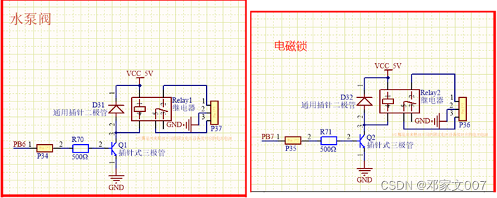
In order to solve the problem of equipment safety and outdoor commissioning of maintenance personnel and engineers , An electronic lock is added on the device shell to ensure the security of the device and to equip it with Bluetooth APP It is convenient to debug and print data information and complete the contactless unlocking function .
2.2 Overall system design architecture
The overall design framework of the fire hydrant monitoring system is shown in Figure 2-1 Shown , In the frame diagram STM32F103C8T6 Single chip microcomputer is the main control core of the whole system equipment , Secondly, the left side of the frame diagram serves as the power supply input port and working voltage conversion function of the whole system equipment , Through the power supply input on the right STM32 The power supply of single chip microcomputer and each module makes the whole system equipment work normally .
The complete working mode of the hydrant monitoring system is to use STM32 MCU initializes each module ; Secondly, the water pressure sensor 、IMU901 gyroscope 、DS18B20 Temperature sensor 、EEPROM、GPS Beidou Positioning carries out corresponding data acquisition and data analysis ; Through again BT04 Bluetooth and NB-IOT The module uploads the parsed data 、 adopt OLED Show time and equipment ID No. and compare the analyzed data with the preset value 、NB-IOT Respond accordingly ; Finally, through the upper computer cloud intelligence APP Obtain data from Alibaba cloud Internet of things server and the upper computer Android Bluetooth APP Get data to render to UI The interface provides customer viewing information .

3 Hardware design of fire hydrant monitoring system
3.1 The whole hardware system consists of circuit design
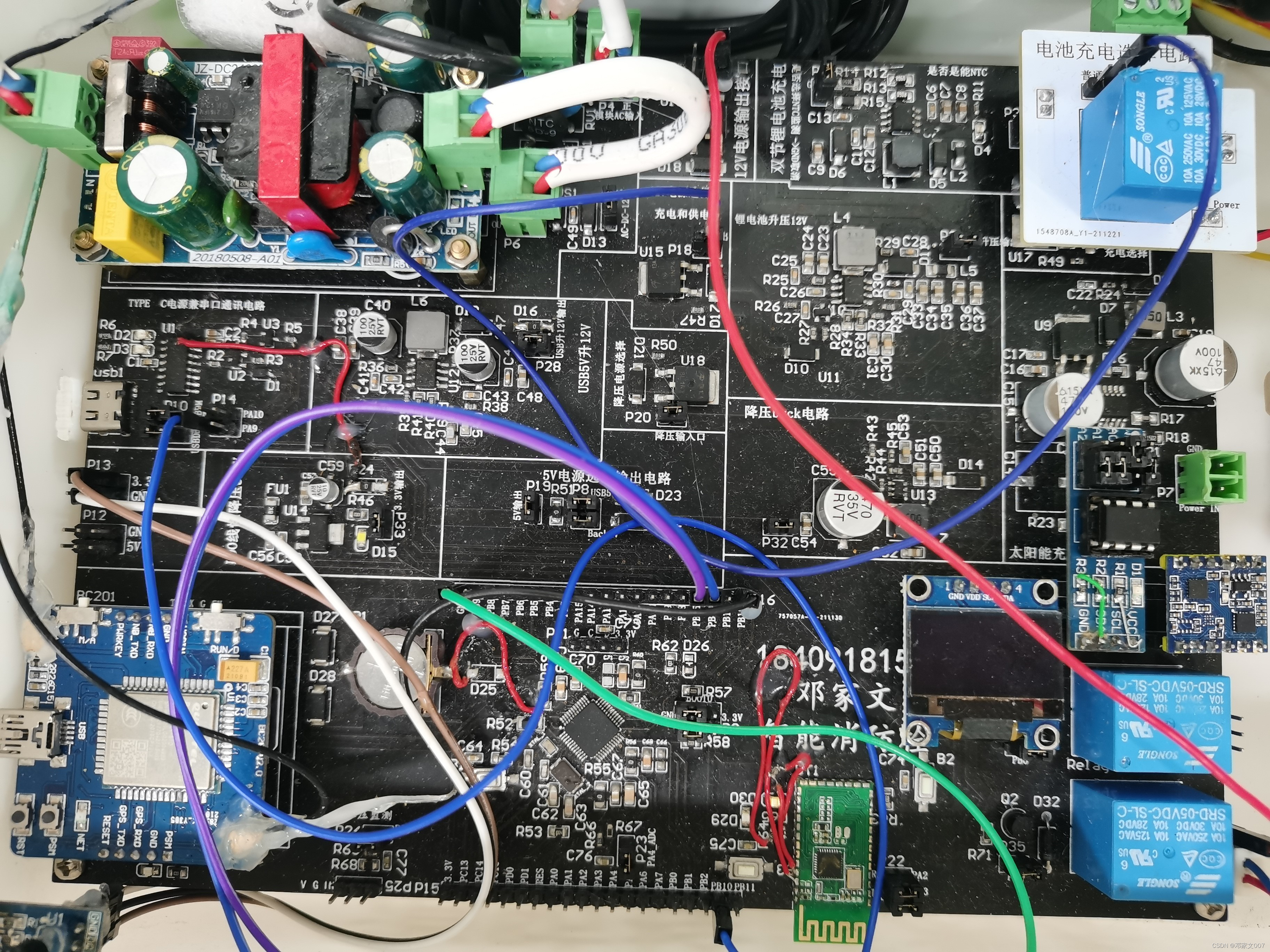
The hardware circuit of fire hydrant monitoring system consists of the following parts :AC-DC Flyback switching power supply circuit 、USB_Type_C Serial data interface circuit 、 Double lithium battery protection circuit 、 Dual lithium battery charging circuit 、LDO Linear voltage stabilizing circuit 、 Solar multi section lithium battery charging circuit 、BOOST Boost circuit 、BUCK Step down circuit 、 Power selection circuit 、ADC A / D conversion circuit 、BT04 Bluetooth module 、EEPROM modular 、NB-IOT modular 、IMU901 Gyroscope module 、OLED display 、STM32 Single chip microcomputer and other circuits . Connections based on the relationship between each hardware module , And cooperate with the driver to complete the overall control and processing of the fire hydrant monitoring system , Finally achieve the expected overall processing work .
The figure below 3-1 It is the power supply system structure diagram of the fire hydrant monitoring system , Is to provide a complete fire hydrant monitoring system 、 Stable 、 Reliable power supply system , Ensure the stability of the system .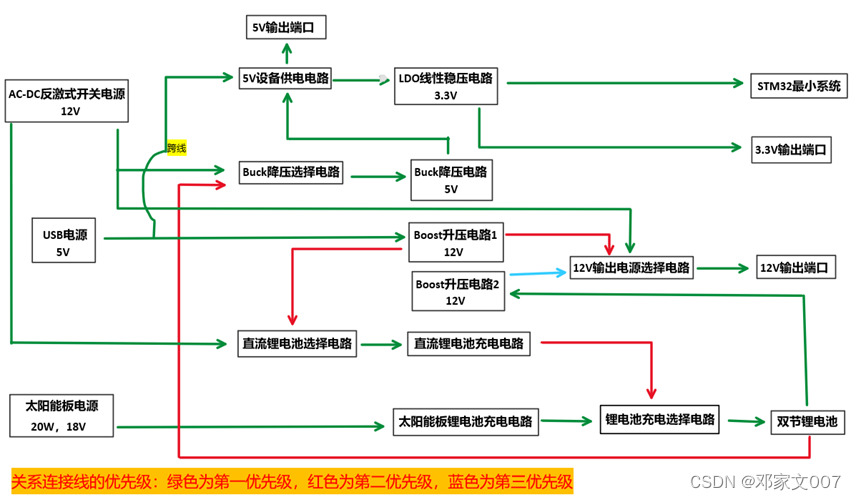
3.2 AC-DC Flyback switching power supply
Of flyback power supply “ Flyback ” It got its name , It means that the output end obtains electric energy when the primary winding is cut off . Flyback power supply is widely used in low-power household appliances , It has the advantages of circuit simplification 、 It can efficiently carry out multi-channel DC input and output 、 High conversion rate 、 Even if the input current is in a large fluctuation range, it can ensure the advantages of relatively stable output power .
Flyback switching power supply is used to input 220V AC mains power is converted to DC output . Because what this system needs to design is 185V-265V Range of AC input voltage and 12V Output voltage and 2A Output current . And choose to use Shenzhen dongke Peninsula Sports Co., Ltd DK124-24W Off line switching power supply IC Just meet the design requirements . The circuit diagram is shown in the figure below 3-2 Shown .
chart 3-2 Flyback switching power supply main circuit
The implementation steps are as follows :
- Fusible link : choice 2A-250V, This is the most critical point of electrical safety , It can quickly cut off the power supply in case of short circuit and overload, so as to protect the subsequent circuit .
- NTC Thermistor : Select the model as 5D-9 Thermistor , It has a 3A Maximum steady state current , It can prevent the equipment that has just been powered on from touching the peak value of the power input to the market, and the surge current will cause irreparable damage to the subsequent circuit .
- Varistor : Choose to have 2.2 Times the AC effective working voltage 14D471K Varistor , It is a voltage limiting protection device , When overvoltage occurs between the two poles of the varistor , It can take advantage of its own nonlinear characteristics , Clamp the voltage to a relatively fixed value , So as to suppress voltage surge and protect the subsequent circuit [1].
- EMI circuit : In the circuit CX1 Of X Safety class capacitor 、LF2 Common mode inductance and R2、R5 Resistance composition EMI circuit , It can suppress noise signals .X Safety like capacitors are called differential mode capacitors , be used for L-N Between the capacitors ,0.47uF/275VAC Of X Capacitance like suppresses the differential mode electromagnetic interference signal of the AC signal input in the AC network ; Common mode inductors can suppress common mode EMI signals , The effect of suppressing interference signal with larger inductance will be better . But when the common mode inductor is connected to both ends of the AC power supply , It is also hoped that the voltage drop on the common mode inductor should be as low as possible ( Voltage drop refers to the amount of differential mode inductance in common mode inductance ), Therefore, coupling is required between common mode inductance windings connected to AC power lines at both ends , Then the common mode inductance is superimposed , Differential mode inductance cancels each other out . The frequency to be suppressed by the power filter needs to be larger than the switching frequency of the switching power supply , In order to reduce the electromagnetic interference of switching frequency as much as possible , choice 150KHz; Series resistance R2、R5 The device can be powered off immediately , Discharge the current on the common mode inductor that generates the reverse induced electromotive force , To protect . Here choose two 150K Of 1206 Encapsulated resistor , Ensure that it does not exceed the rated power .
- The rectifier shall not exceed the rated power 1N4007 diode .
- For the sake of stability , The rectifier and filter capacitor shall be a low-frequency filter 47uF/400V Electrolytic capacitor with high frequency filtering function 10nF/1000V The ceramic capacitor of , Increase the stability and reliability of input power supply of flyback transformer .
Selection of rectifier filter capacitor :
85-265V Under the AC input state of international common voltage level , The rectifier filter capacitor bears about 27mA/W Effective value of ripple current .
220V AC voltage level under input voltage state , The rectifier filter capacitor bears about 13.3mA/W Effective value of ripple current .
The capacitor can be selected according to the effective value of the current . - RCD The clamping circuit is shown in the figure R3、R4、C4、D6 form , Its function is to transfer the transformer leakage inductance energy storage to the capacitor . Because there is a transformer reset voltage on the switch tube ( Recoil voltage )、 DC bus voltage and induced electromotive force of transformer leakage inductance . The two voltages of the front transformer recoil voltage and DC bus voltage are known constant values , And these two voltages are within the calculation . The induced electromotive force produced by transformer leakage inductance is inevitable , But we don't want it in the design . Because the switching speed of the switch tube is very fast , This makes the induced electromotive force of transformer leakage inductance very high as the switching speed of the switch tube becomes faster [2], It's very dangerous . The flyback switching power supply circuit adopts the model of 2A223J Of 22nF capacitance ; The purpose of the resistor is to release the clamping power of the capacitor , Prepare for the next clamping , The rated power of the resistor shall not be exceeded during operation here ; Diodes use rectifier diodes with fast reverse recovery performance , And the rated voltage of diode shall not be lower than DC bus voltage .
Clamp capacitor selection :C=(L_r×I_m2)/((V_22-V_1^2 ) ) , among L_r Transformer leakage inductance ,I_m Switch peak current ,V_2 Clamp capacitor voltage after clamping ,V_1 Clamp capacitor voltage before clamping . - Flyback transformer uses EE25 skeleton , The ratio of the original edge to the surrounding edge is 90:12, The primary and wound pins are respectively 1,3 and 6,8, The inductance is 0.6nH.
- In the figure D3 The diode shall be a Schott diode with low voltage drop and unidirectional conductivity , Only when the transformer is turned off, the power can be output to the output end and the loss is low .
- In the figure C10、L1、C5 Make up the LCΠ Type filter circuit , It is mainly used for output filtering .
- Voltage feedback electrical route R7、D5、U2、C13、C14 form , This voltage feedback circuit is based on the official scheme , Ensure that there is no big error in the feedback link .
Its operation and design principle : First pass the unfiltered voltage through R7( Function of current limiting protection optocoupler ) And the filtered voltage is respectively connected to the positive pole of the input end of the optocoupler through the zener diode 、 In negative pole , The unfiltered voltage can truly feedback the change of output voltage , The filtered voltage can stabilize the zener diode between its rated voltage , When no output voltage increases or decreases, the voltage of the LED at the input of the optocoupler will be affected , Therefore, the operating current of the LED in the optocoupler will also increase or decrease , Further, when the luminous brightness of the LED changes, the conduction current of the triode at the output end of the optocoupler also changes , Eventually lead to KD124 Of 3 Pin FB Input current changes , When FB When the input current increases ,KD124 The output pulse width of is correspondingly narrowed , Reduce the output voltage .(C13、C14 It's filtering ) - In the figure CY1 and CY2 by Y Class capacitor ( Also called common mode capacitor ), It is also a safety capacitor , The function is to suppress common mode electromagnetic signals and separate the ground wire on the circuit board into safe isolated ground (PGND) And high voltage (GND).
- A safety protection circuit is added to the circuit output stage in the above figure . Here's the picture :

3.3 Lithium battery charging circuit
3.3.1 Solar panel lithium battery charging circuit
Because a plurality of lithium batteries in series and parallel are used to supply power to the circuit board , So after repeated screening , I have chosen one of Ruyun Electronic Co., Ltd., which has the function of automatically adjusting the power supply input of solar panels IC, Its model is CN3795, It is a multi cell lithium battery charging management integrated circuit IC, have PWM The combination of step-down mode 6.6V-30V Wide voltage input . It's amazing , Its charging current can be as high as 4A. Therefore, it is very suitable to use it to charge multiple lithium batteries separately .
CN3795 The power management chip has trickle charging 、 Constant current charging 、 Constant voltage charging 、 Sleep and other modes .CN3795 The power management chip controls the battery voltage through a built-in comparator 、 Input the power supply voltage and charging current respectively with the corresponding built-in reference voltage 、 Circuit comparison , So as to automatically switch to the corresponding mode .
CN3795 Power management chips have other advantages , It has the function of tracking the input maximum power point of the solar panel , When using solar panels as input power , Its internal circuit can automatically track the input maximum power point of the solar panel , In this way, the design engineer no longer has to consider the worst case . because CN3795 The power management chip can maximize the input power of the solar panel into the output power of the , therefore CN3795 The power management chip is very suitable for the use of solar panel power .
CN3795 The charging mode and the maximum power tracking function of the solar panel increase the service life of the lithium battery and improve the outdoor self charging ability , Thus, the endurance capacity of outdoor equipment and the stability of self guarantee work are greatly increased without supervision 、 reliability .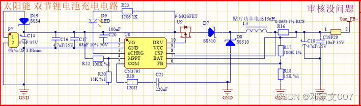
- D19 yes SS34 Schott diode , The purpose is to prevent reverse connection of input power supply .
- C14、C16、C17 Input filter capacitor , It can filter the ripple of the input power supply and restrain the high-frequency oscillation caused by parasitic inductance at the switching moment . according to DataSheet manual ,C16、C17 Choose to use... Separately 4.7uF/35V and 68nF/50V Of , and C14 Electrolytic capacitors are mainly used for low-frequency filtering , We need to choose according to the actual situation ( No, the larger the capacitance, the better , It also needs to be based on its equivalent resistance value ESR choice , Otherwise, the extremes of things will be reversed ).
- R22(15KΩ) and R20(1KΩ) These two resistors are used to adjust the maximum power point tracking of solar panels . The maximum power point voltage is determined by the following formula :V_MPPT=1.205×(1+R_22/R_20 ) , So set up V_MPPT about 19.3V, The solar panel used together ( Parameters :18V1.1A20W).
- R16 by Rcs resistance , It is used to set the constant current charging current , The constant current charging current is determined by the following formula :I_CH=120mV/R_CS , The maximum charging current of this circuit can reach 2A.
- R17、R18 These two resistors are used to set the constant voltage charging voltage , The constant voltage charging voltage is determined by the following formula :V_BAT=1205×(1+R_17/R_18 )+I_B×R_17 ,(I_B yes FB The bias current of the pin , Its typical value is 60nA).
- L3 Is the power inductor , According to the circuit analysis above , In the normal working phase , The transient current on the inductor changes periodically . When PMOS When the drain source of the tube is connected , The input power supplies charge the inductor , The electric potential energy on the inductor increases ; When PMOS When the tube drain source is disconnected , The inductor releases potential energy to charge the battery . When the inductance value on the power inductance increases , The ripple current on the inductor decreases inversely , Positive linear relationship ; The input voltage and ripple current are opposite , In inverse linear relation . Because the ripple current on the inductor and the ripple charging current have a positive linear relationship , Therefore, the ripple current of the inductor should be controlled within a relatively reasonable range . The ripple current of the inductor can be estimated by the following formula :ΔI_L≡1/fL×V_BAT×(1-V_BAT/V_CC ), among :f Is the switching frequency (300KHz),L Is the inductance value ,V_BAT Battery voltage ,V_CC It's the input voltage . When selecting inductance value , The ripple current of the inductor can be limited to ΔI_L≤0.3×I_CH , among I_CH Is the charging current . In addition to meeting the above limitations , We also need to satisfy this formula :L>5×(V_CC-V_BAT ) . Therefore use 15uH The inductance of .
- U9 yes P Ditch MOS Field effect tube , choice PMOS Tube needs attention MOS Breakdown voltage of field effect transistor BVDss Must be greater than the maximum input voltage , The second factor to consider is the on resistance R_ds(on) , Total gate charge Q_g, Reverse conduction capacitance C_RSS, Input voltage and maximum charging current .P Ditch MOS The maximum power consumption of the field effect transistor can be approximated by the following formula :P_d=V_BAT/V_CC ×R_ds(on) ×I_CH^2×(1+0.05ⅆT), among :P_d yes MOS Power consumption of field effect transistor ,V_BAT Is the maximum voltage of the battery ,V_CC Is the minimum input voltage ,R_ds(on) yes P Channel fet at room temperature (25℃) On resistance under ,I_CH Is the charging current ,dT yes P Ditch MOS Actual temperature and room temperature of field effect transistor (25℃) Temperature difference of . In addition to the conduction loss , There are also switching losses , Switching loss increases with the increase of input voltage . When the input voltage is less than 20V when , The conduction loss is greater than the switching loss , Give priority to those with small on resistance MOS Field effect transistor ; When the input voltage is greater than 20V when , The switching loss is greater than the conduction loss , Priority is given to reverse conduction capacitance CRSS The smaller MOS Field effect transistor [3]. commonly C_RSS The value of the MOS The technical specifications of field effect transistors are listed , If the capacitance value is not specified , By formula C_RSS=Q_GD/V_DS , To estimate .
To sum up , Type selected : model AOD413A Of PMOS tube .
3.3.2 DC lithium battery charging circuit
In order to charge the lithium battery indoors , Select the model as EUP8209 This constant current 、 Constant voltage lithium ion battery charger controller using current mode , The controller used here is 8.4 Version of , It has a wide input range of power supply voltage (8.9V to 20V)、12 Hour charging end timer 、 Low power auto sleep 、 Support as much as 3A Charging current, etc , Therefore, it is very suitable for indoor charging equipment , It can greatly prolong the service life of equipment and lithium battery .
- The resistance in the figure above R13 and R12 A resistor is formed RSENSE, This resistor controls the output current , The output current is determined as follows :R_SENSE=100mV/I_out , So it is concluded that RSENSE The resistance of is 33mΩ, This circuit uses two 60mΩ In parallel instead of 30mΩ resistance .
- L1 The selection condition of inductance shall use the official reference scheme , At maximum input voltage 50% Under ripple conditions , The determination formula of inductance is as follows :L=(V_out/(500KHz×50%×I_out ))×(1-V_out/V_inMax ), among :500KHz Is the switching frequency ,V_inMax Is the maximum input voltage . After calculation L about 6.5uH.
- Because no 6.5uH The inductance of , Here's the choice 6.8uH Instead of inductance , Then the determinant of the maximum ripple current is as follows :∆I_L=(V_out/(500KHz×L))×(1-V_out/V_inMax ), The maximum ripple current is calculated ΔI_L about 1.433A.
- Consider the maximum ripple current , The decisive formula is as follows :V_(out(ripple))=((∆I_(L(Max))×ESR))/2, among ESR Is the equivalent resistance , about 0.1Ω. The maximum ripple current is calculated to be about 72mV.
- Calculate the peak inductive current , Leave a margin , Prevent the output inductance from being too large to cause damage to the subsequent circuit ,, Then the determinant of the peak inductance current is as follows :I_LPK=I_out+((∆I_L)/2), The peak inductance current is calculated I_LPK about 3.7A.
- In addition to the necessary components of the above circuits , There are also some additional components , It makes the lithium battery charging circuit work more stable and reliable . Such as D6 Schott diode SS34, This is to prevent the reverse connection of the input power supply ;C9 Capacitor is used to input filtering function ;R15 The identification in the circuit diagram is wrong ,R15 It's a 10KΩ Of NTC Thermistor ; capacitance C6、C8 The functions are high-frequency filtering and low-frequency filtering ; Magnetic beads L2 It is used for filtering and debugging .
3.3.3 Double lithium battery protection circuit
Fullman microelectronics Group Co., Ltd TC2110 Series double section series lithium ion rechargeable battery protection IC, It has the function of charging 、 Mechanism of over discharge and over current protection . And the figure below uses TC2120-CB This kind of IC The double lithium battery protection circuit is designed , according to DataSheet Manual design , Such as 3-5 Shown .
3.4 Power supply voltage conversion circuit
3.4.1 Lithium battery and USB Input power 12V Boost circuit
The boost circuit is also called Boost circuit , In this circuit system, a 12V Step up circuit of , Models for FP6296 Of IC Is a current mode boost DC-DC Asynchronous converter IC, Support 2.7V-12V Working voltage , Basically meet the design requirements .
- resistance R31 It is used to set the peak current of the switching circuit , And the resistance value 51KΩ-150KΩ Corresponding to 2A-10A direct . So here we use 51KΩ.
- resistance R33 and R34 It is used to set the output voltage , Its determinant :V_out=1.2×(1+R_33/R_34 ), The output voltage is calculated Vout about 12.11V.
- inductance L4 The alternative of Boost One of the keys to circuit selection . The following figure for Boost Topology circuit , According to the volt second law : Inductance voltage when opening Opening time = Inductance voltage at shutdown Off time , In fact, this is to obey the law of conservation of energy , According to the volt second law :
〖U(L)〗_on×T_on=〖U(L)〗_off×T_off
Using Kirchhoff's law, we can know ,〖U(L)〗_on=V_in,〖U(L)〗_off=V_o-V_in, And because of the switching cycle 〖T=T〗_on+T_off And duty cycle D=T_on/T, Combined with the above conditions, we get :D=(V_o-V_in)/Vo, This is calculated by neglecting the partial voltage of Schott diode .
① According to the previous conclusion D=(V_o-V_inMin)/Vo Computable , The duty cycle is about 0.43; according to T=1/f( here f Is the switching frequency 400KHz) obtain T by 2.5us; according to T_on=DT obtain d_t=1.083us.
② because d_i Is ripple current , therefore di=ΔI_L. Usually, the ripple of the voltage stabilizing circuit is set to be... Of the maximum load current 0.4 times , The maximum load current is the maximum average current flowing through the inductor I_Lmax, The average current of the inductor is the current output by the inductor when the switch is disconnected , Therefore, the formula is :I_Lmax=I_outmax/(1-D), therefore d_i=〖ΔI〗_L=0.4×I_Lmax=0.4×〖 I〗_outmax/(1-D), At last, calculate d_i About equal to 1.4A.
③ So according to L=V_in×d_t/d_i =V_in×T_on/〖ΔI〗_L Get the inductance value L about 5.26uH, This is because the purchase of such inductors is omitted , So we used 3.3uH Of , When the load is increased and the input voltage is too small, the switching power supply will enter the cut-off mode .
④ The peak current is determined by :I_LPK=I_Lmax+(〖ΔI〗_L )/2=1.2〖I 〗_Lmax= 4.212A.
- Input 、 The calculation formula for the selection of output filter capacitance is as follows :
Input filter ceramic capacitance formula :C_i≥V_i/(8×f^2×L×〖∆V〗_i )×(1-V_i/(V_o+V_d ))
Input filter electrolytic capacitor formula :ESR≤(〖∆V〗_i×f×L)/V_i ×(V_o+V_d)/(V_o+V_d-V_i )
Output filter capacitance formula :C_o≥I_o/(f×〖∆V〗_o )×(1-V_i/(V_o+V_d ))
Output filter electrolytic capacitor formula :ESR≤〖∆V〗_o/((V_o+V_d)/V_i ×I_o+V_i/(2×f×L)×(1-V_i/(V_o+V_d )) )
According to the above formula, the input and output capacitance with appropriate capacitance can be selected , And the working voltage is based on the actual working voltage 1.5 Double selection is enough . - Zener diode in the circuit diagram D10(12V Steady pressure )、N-MOSFET Field effect transistor U11 And resistance R27、R28、R26 Form an automatic enable and cut-off circuit , When input by flyback switching power supply , Will cut off FP6296 Step up work of . Here is the resistance R26 It only serves as current limiting protection .
- Other electronic components are selected in their DataSheet The manual provides reference .
3.4.2 Buck Step down circuit
JW5060T This kind of Buck step-down IC With wide input voltage (4V-24V)、 The maximum output current is up to 3A And Gotha 95% The efficiency of 、 Synchronous conversion work .
- According to the circuit analysis and using the volt second rule, we can get D=V_out/V_in .

because U=L×d_i/d_t , among U Subtract the output voltage from the input voltage V_in-V_out 、L For inductance 、d_i Is the ripple current of the inductor 、d_t Conduction time , According to this formula, the center , Calculate the required inductance L, Steps are as follows :
① Because the input voltage is 6.8V-12V Within the scope of , therefore D=5/12 and D=5/6.8.
② Conduction time d_t=T_on=DT=5/(12×800KHz) and 5/(6.8×800KHz).
③ Ripple current on the inductor d_i=〖ΔI〗_L=0.4×I_Lmax=0.4×( I_outmax)/(1-D) about 1.67A and 10A.
④ So according to L=(V_in-V_out)×dt/di=(V_in-V_out)×T_on/〖ΔI〗_L Get the inductance value L about 0.17uH-2.2uH This range . So I chose 4.7uH The inductance of , Leave a margin .
According to the IC Of Datasheet The calculation method of inductance is also given , as follows :
L=V_out/(f_s×〖∆I〗_L )×(1-V_out/V_in )
It's not hard to find out , The calculation of this formula is the same as the above calculation , The above formula is expanded as follows :
L =1/〖ΔI〗_L ×(V_out-(V_out^2)/V_in )×1/f_s
= 1/〖ΔI〗_L ×(V_in-V_out )×V_out/V_in ×1/f_s
= ( 1)/d_t ×U× D×T
The above explanation shows that the previous calculation is no problem .
⑤ The peak current is :I_LPK=1.2I_Lmax≈28.8A.Input 、 The calculation formula for the selection of output filter capacitance is as follows :
Input filter ceramic capacitance formula :C_i≥I_o/(〖∆V〗_i×f)×V_o/V_i ×(1-V_o/V_i )
Input filter electrolytic capacitor formula :ESR≤〖∆V〗_i/(I_o+V_o/(2×f×L)×(1-V_o/V_i ) )
Output filter ceramic capacitor formula :C_o≤V_o/(8×f^2×〖∆V〗_o×L)×(1-V_o/V_i )
Input filter electrolytic capacitor formula :ESR≤(〖∆V〗_o×f×L×V_i)/(V_o×(V_i-V_o))resistance R44、R45 It's used to set up Buck The output voltage of the step-down circuit , The determinant is :
V_FB=V_out×R_2/(R_2+R_3 )Other electronic components are selected in their DataSheet The manual provides reference .
3.4.3 LDO Linear voltage stabilizing circuit
LDO The linear voltage stabilizing circuit is a low-voltage drop circuit , The effect of chopping and reducing voltage is achieved at the cost of the loss of the internal switch . Here we need to design a system that can 5V Depressurization is 3.3V Low dropout step-down circuit , After multiple screening , Choose one that is commonly used ASM1117-3.3 Of LDO Linear voltage regulator 4Pin Of IC, It is a low static current 、 The output current can be as high as 1A、 Positive voltage regulator with stable output voltage and low power consumption , It is very suitable to be used alone for STM32F103C8T6 This chip supplies electricity .
3.5 Power switching circuit
3.5.1 Automatic priority switching input power circuit
The automatic priority switching input power supply circuit is that the circuit board automatically selects the minimum consumption of its own backup power supply ( The lithium battery ) Power supply for power supply work , This conforms to the original design requirements : Reduce energy consumption 、 Increase endurance energy 、 Can work steadily and reliably .

3.6 Single chip microcomputer control circuit
3.6.1 STM32F103C8T6 Minimum system circuit
Use model STM32F103C8T6 Enhanced series MCU Design the minimum system of single chip microcomputer . The minimum system of single chip microcomputer refers to the minimum circuit system composed of the least components , And it can work properly , It is the most basic functional unit [4].
STM32 The minimum system design steps of single chip microcomputer are as follows :
- In order to keep the internal of the minimum system after power failure RTC The clock works properly , A button battery circuit is added to continue after power failure STM32 Inside RTC Clock life , To ensure its normal operation .

- This minimum system uses LDO Linear regulated power input 3.3V Single power supply . Here's the picture 3-11-2 As shown in the circuit diagram , This circuit is a reference to the official STM32F103X8 Data book design .

- Single chip microcomputer completes different instruction functions through complex sequential circuits , And the clock circuit is the single-chip computer “ pulse ”, It controls the working rhythm of the single chip microcomputer . According to the official data manual , Two clock circuits are designed , They are the external low-speed clock circuit and the external high-speed clock circuit .

- Reset is the essential function of the minimum system of single chip microcomputer , It can reset the system when the single-chip microcomputer program is stuck or the program is out of order , Make its program run again . Reset can be divided into hardware reset and software reset , The hardware reset circuit is as follows :

- BOOT The circuit is STM32 Circuit for manually selecting three bootstrap modes .

- SWD It is a serial bus debugging interface , It has the function of PC The program compiled on the host computer is downloaded to the single chip microcomputer and the two terminal devices for running and debugging ,SWD The circuit is as follows :
chart 3-11-6 SWD circuit
The capacitance in the circuit above C73 It is to filter out the ripple when connecting to the external simulator , Ensure that the simulator works stably and reliably .
3.6.2 Type C Interface USB To serial circuit
Type C Interfaces are now widely used on terminal mobile devices , It will not be too complicated in circuit design and connection , And will be Type C Interface USB Signal conversion to serial port signal is now the most common on embedded development boards CH340 Family chips , It's a USB Bus adapter chip , It can be realized USB To serial port or USB Turn to print port , And it has full speed USB Device interface , compatible USB V2.0. After screening , Choose to use CH340C This kind of IC, This chip has built-in clock generator , There is no need to add crystal oscillator and oscillating capacitor , Therefore, some cost materials can be saved .
- Type C The connection is shown in the figure above D+、D- Namely USB2.0 The positive and negative of the differential signal , and VUSB yes USB2.0 Bus power supply , That is to say USB The input power supply of .
- CH340C Is the key to realize serial port data transmission , In addition to reference CH340 Official Datasheet The reference circuit provided realizes the serial port data transmission , After consulting the relevant embedded hardware development books, I refer to some USB To serial port circuit MCU Of ISP Connect , So as to achieve direct passage USB Download program . Realization USB Download program circuit design steps :
① The first thing to know is STM32 At startup, the bootstrap pin (BOOT) Select three bootstrap modes , The three modes are : Bootstrap from program flash memory 、 Bootstrap from system memory (ISP Pattern )、 From the inside SRAM Bootstrap [5]. When BOOT0 When grounded ,STM32 It will bootstrap from the program flash memory , To enter the user program ; When BOOT0 Pick up 3.3V and BOOT1 When grounded ,STM32 It will bootstrap from the system memory , So as to enter the factory preset Bootloader Update the program .
② STM32 Of ISP Connection process : First RTS Output low level , At this time, the circuit is S8550 It's going to turn on ,BOOT0 Pulled high , Configure to ISP Pattern ; secondly DTR Output high level , At this time, the circuit is S8050 It is also connected ,STM32 Of RESET The reset pin is pulled low , bring STM32 Restart and enter ISP Pattern ; When the system enters ISP After the model ,RTS Output high level and DTR Output level , Make it BOOT0 and RESET Restore to initial state ; Finally, the program is downloaded , Automatically run user programs .
③ In order to observe the serial port data transmission and look good , A serial port TX and RX The transmission lines are connected to two pull-up cables respectively 4.7K Two colors of resistors LED The lamp .
3.6.3 External expansion power interface circuit
To ensure that the equipment can supply power to the expansion module , There is an increase in 3 Expand the power interface outside the class , Respectively 12V Interface 、5V Interface and 3.3V Interface . The circuit diagram is as follows :
This schematic diagram shows the wrong pins , Watch carefully , You can refer to the modified drawing
3.6.5 ADC A / D conversion circuit
ADC The analog-to-digital conversion circuit is to convert the voltage analog signal with continuous value into the binary coded digital signal of the computer . because STM32 The processor has built-in ADC converter , Its analog voltage conversion range 0-3.3V, Therefore, when the external analog voltage exceeds STM32 If the specified analog voltage conversion range , It is necessary to use an external voltage divider circuit to control the external input analog voltage within the specified analog voltage conversion range , The general voltage dividing circuit needs to use a resistance with a resistance value of more than 1000 ohms and a precision of 1% , Ensure that the analog voltage of external input can be accurately converted in equal proportion . Adding a filter capacitor to the external input analog voltage interface can effectively filter out some interference voltage signals . This paper designs a water pressure sensor detection and battery voltage detection ADC A / D conversion circuit , The circuit design is as follows :
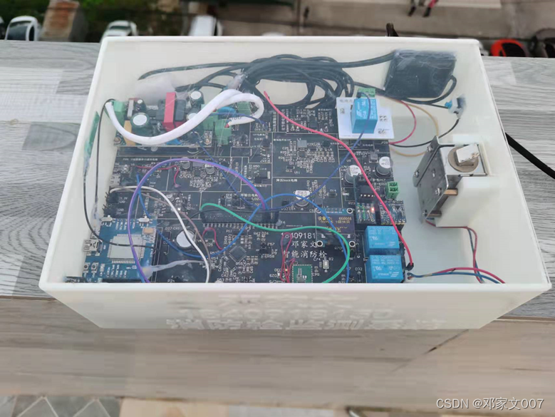
3.7 Fire hydrant monitoring system enclosure
The shell of the fire hydrant monitoring system uses solidworks Software drawn 3D Model [6], And then through 3D Made by the printer ,3D The model and shell are shown in the figure below 3-17 and 3-18 Shown .

4 Software design of fire hydrant monitoring system
4.1 Software system design of lower computer
4.1.1 General idea of overall software system design
The software system in a system device is to make a pile of hardware like headless flies work orderly with each other , Finally achieve the set work objectives . However, it is very necessary to consider the logical relationship between each functional program when designing the software system , Therefore, a lot of analysis and integration work needs to be done before writing the software system program , Each functional aspect and each program execution step need to be organized clearly , Draft these aspects into a preliminary architecture diagram of the software system . Because good programming habits should draw the program flow chart before programming , The program flow chart is drawn with reference to the preliminary architecture diagram of the software system . Before writing the program with reference to the program flow chart, the engineering documents shall be modified BSP engineering management , The generated file will be compiled 、 Called library file 、 The driver files of each function module written by yourself are classified into folders , This makes the whole project beautiful 、 The drivers of each functional module are clear 、 Easy to read .BSP After the completion of project management, the library files shall be introduced and the driver of each functional module shall be written in an orderly manner 、 debugging , Try to minimize the driver error rate of each functional module , Finally, the main program runs the program in the stage of logical integration of the drivers of various functional modules BUG Fewer occurrences .
4.1.2 Main program flow chart design
The main program is a part of the software system “ trunk ”, It is to “ The root ”( Driver of function module ) Program to “ crown of a tree ”( Graphic interface, etc ) in , The program flow chart is a visual representation of the running process of the main program , It can quickly clear the logical relationship between each subroutine and the main program . The main program flow chart is shown in the figure below 4-1 Shown .
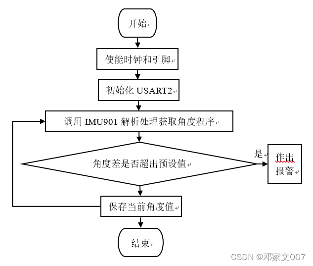
The main program of fire hydrant monitoring system runs : When the fire hydrant monitoring system is powered on , The first step of the main program is initialization STM32 Internal underlying drivers . The second step shows Logo. Step 3 initialize each module ; Step 4: obtain the first gyro angle data . Step 4: enter the main circulation body , The student number, name and equipment will be displayed in turn according to the number of cycles in the main cycle ID Number , And the time is refreshed every time the loop body circulates ; Then get the ambient temperature 、 Chip temperature 、 Water pressure 、 Gyroscope angle 、 The value of the battery voltage , If the ambient temperature is higher than the preset value, it will trigger the solenoid valve of the cooling equipment to open for cooling , If the difference between the current gyroscope angle and the last gyroscope angle is greater than ten degrees, an alarm will be triggered ; Finally, upload the collected data to the cloud and start a new cycle .
4.1.3 EEPROM Get the device ID No. implementation
EEPROM This kind of read-write memory can be used in many devices . Implementation steps : The first step is to enable the corresponding clock and pins ; The second step will be STM32 Of IIC Drive initialization ; The third step is to use IIC The driver initialization model is AT24C20 Of EEPROM Memory ; The fourth step is to write the model AT24C20 Of EEPROM Driver for memory read / write operation ; Step 5 read EEPROM Internal equipment ID Number , Finally, it is displayed to OLED On the screen .

4.1.6 BC20 Internet of things module wireless communication and GPS location
BC20 The IOT module is a very important part of the fire hydrant monitoring system [7]. Implementation steps : The first step is to enable the corresponding clock and pins ; The second step is to write a test BC20 Whether the IOT module starts and communicates normally ; The third step calls the program written in the second step to detect BC20 Whether the IOT module is normal ; The fourth step is to write GPS Activate the connected program ; Step 5 calls the program written in step 4 to GPS Activate connection ; Step 6: write a program to connect to the Alibaba cloud Internet of things platform ; Step 7 call the program written in step 6 to connect to the Alibaba cloud Internet of things platform ; Step 8: write and obtain GPS Positioning procedures ; Step 9 call the program written in step 8 to obtain GPS Location information ; Step 10 upload the collected data and other information to the Alibaba cloud Internet of things platform .
4.2 Design of upper computer software system
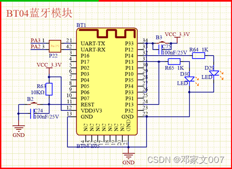
The Android Bluetooth APP It's using JAVA And a few HTML Language in Android Studios Designed by the development software platform . It is mainly used for wireless short-distance communication with the lower computer , It is convenient for debugging and control [8].
Because the program flow chart is usually drawn before the program is written , Such as 4-6 Shown .
Android Bluetooth APP Design steps for : The first step is to add the program with all relevant permissions ; The second step is to write a program to determine whether the mobile phone supports Bluetooth function ; Step 3 write a program to turn Bluetooth on and off , Before turning on Bluetooth, first call the program written in step 2 to check whether the mobile phone supports Bluetooth function , Make sure you don't do useless work ; Step 4: write a program to search for nearby Bluetooth devices ; Step 5 call the program written in step 4 to search for nearby Bluetooth devices , Then debug printing and log viewing , Ensure that the name and address information of the accessory equipment can be found normally ; Step 6 write and create broadcast and dialog list , Store the searched name and address information of nearby Bluetooth devices one by one in the program presented in the dialog list ; Step 7: call the program written in step 6 to observe. The found information of nearby Bluetooth devices is normally displayed in the dialog box list ; Step 8: write the button function that can be triggered by clicking on each line of the dialog list and the program to establish the relationship between each line of the button in the dialog list and its corresponding Bluetooth device information ; Step 9 call the program written in step 8 to observe whether the two devices are really connected ; Step 10 write a program to send data such as input in the edit box ; Step 11 call the program written in step 10 to check whether the receiver application receives the sent data ; Step 12 write a program to receive data in real time ; Step 13 run the entire application , Observe whether each function operates normally ; Step 14 write the button to send relevant control commands ; Step 15 test the whole machine , Ensure the normal communication between the upper computer and the lower computer .
5 Fire hydrant monitoring system test
5.1 SWD Interface burning program test
Here's the picture 5-1 Shown , Through the DuPont line ST-Link The emulator is connected to SWD Interface , And then use IDE Software Keil Program compilation , And perform the burning procedure . It's clear from the picture that ,keil The software will be compiled .hex There are no errors in the file 、 Without warning, it is burned into the single chip microcomputer .
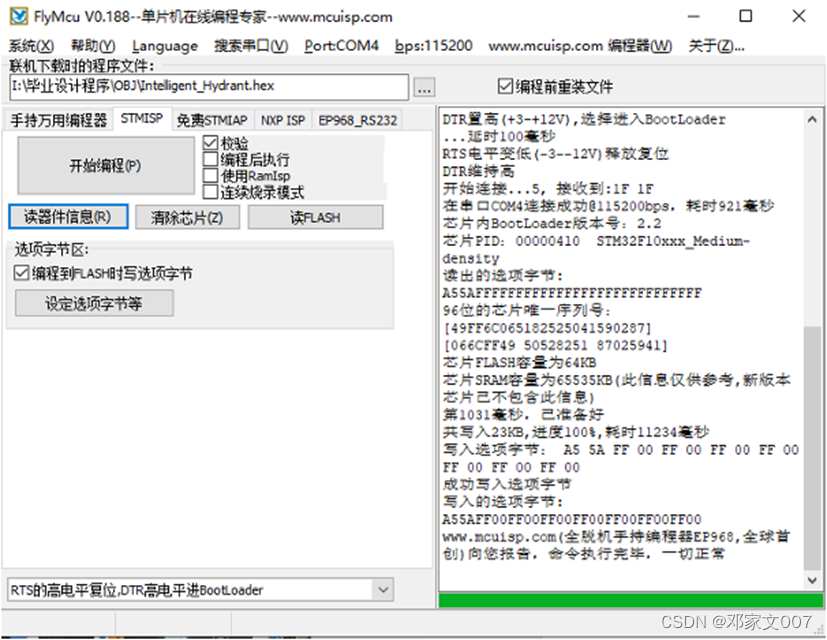
5.2 USB Interface burning program test
Here's the picture 5-2-1 Shown , Connect Type C Type of USB After the interface , Trigger through the upper computer STM32 Get into ISP Bootstrap mode , Then proceed to the burning procedure , It is clear from the picture that , This burning method will also be compiled .hex File for burning , The progress bar and log at this time can reflect that the program burning work is in progress . The figure below 5-2-2 Shown , The progress bar and log at this time reflect that the program burning has been completed 
5.3 Fire hydrant monitoring system power on and start test
When the fire hydrant monitoring system is powered on , The device enters the initialization phase of various built-in peripherals and modules , Here's the picture 5-3-1 Shown , This figure shows the log information printed out when the initialization works normally after the device is powered on . And the following figure 5-3-2 It refers to the normal working state of each module equipment under the normal condition of initialization after the equipment is powered on and started , and OLED Displaying the normal time also indicates that the initialization of the device is normal .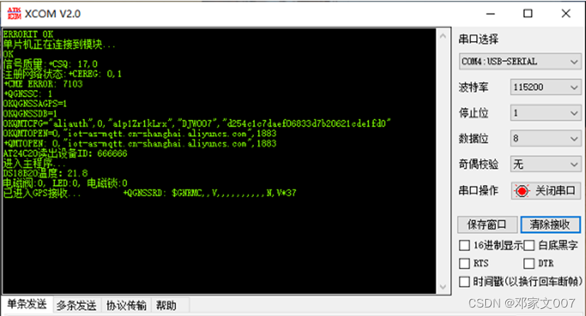

5.4 Cloud intelligence APP Wireless remote observation and control equipment test
Use the cloud intelligence provided by alicloud life IOT platform APP Remote observation and control of fire hydrant monitoring system equipment , Here's the picture 5-5-1 Shown , On the right APP The data information uploaded by the received device has been displayed , When APP Press the button , The lower computer will trigger actions such as unlocking , It can be seen from the equipment phenomenon on the right of the figure that its remote control function is normal , Its function is to realize wireless unlocking ( Generally, close range wireless Bluetooth is used to unlock the lock ) And in the cold season in the north, the electromagnetic valve can be triggered artificially to release antifreeze or the high-temperature area can be watered for physical cooling , Protect hydrant equipment . as for LED The lamp is only used for testing , It has not been used in practice . chart 5-5-2 It is the log and chip temperature recording curve graph that receives the data printout of the upper computer ( Ensure that the device chip operates normally ).

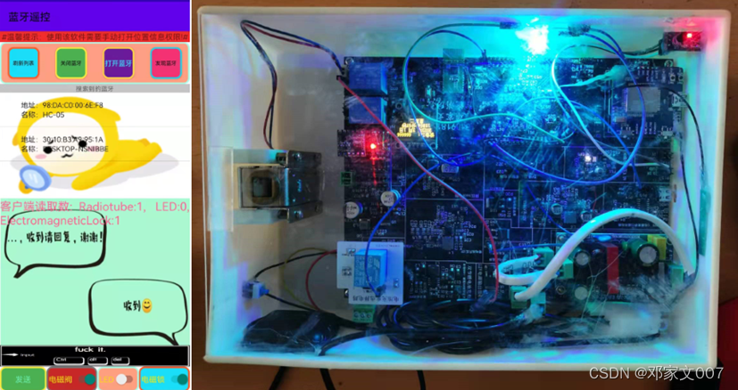
5.5 bluetooth APP Wireless short-range observation and control equipment test
Use Bluetooth APP Achieve short-range wireless data transmission , Here's the picture 5-5 Shown , Use Bluetooth as shown on the left APP Send the command to open the solenoid lock and solenoid valve , And receive the data returned by the upper computer ; The picture on the right shows that the lower computer opens the solenoid lock and solenoid valve , The upper middle two indicator lights also light up , Its purpose is not only to realize wireless unlocking and check debugging information in a short distance , It is also a preparation for future wireless upgrade and other extended functions .
5.6 Cloud intelligence APP obtain GPS Positioning test
Here's the picture 5-6 Shown , Cloud intelligence APP Get the location information uploaded from the intelligent fire hydrant , The positioning information is longitude and the left side of dimension . In the following figure, you can also see that the obtained coordinate values are the actual coordinate values 100 times , This is because of cloud intelligence APP The data presented shall be accurate to two decimal places at most , Therefore, the positioning coordinate data uploaded by the lower computer is expanded 100 Times before uploading .
It can be seen from the following figure test table , Uploaded by the lower computer obtained by cloud intelligence GPS The longitude and latitude data of positioning is the same as that obtained by mobile phone GPS The positioning longitude and latitude data only deviates from the fifth digit after the decimal point . In practice , Error in 10 Rice range , The accuracy is considerable .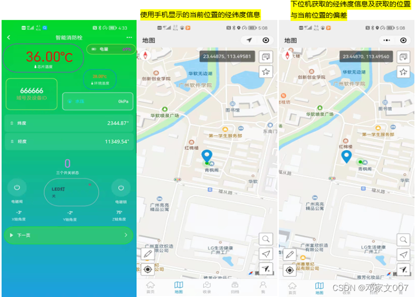

5.7 Three input power tests
Through flyback switching power supply 、Type C Type of USB The interface and the solar panel are three kinds of input power supplies to supply power to the fire hydrant monitoring system . Pictured 5-7-1 Shown , When the flyback switching power supply is connected , The indicator light for normal operation of flyback switching power supply will turn on , At this time, the circuit will preferentially use the input power supply as the power supply , The phenomenon is that the charging indicator light of the dual lithium battery circuit is turned on , Indicates that the lithium battery is charging , And the equipment is in normal operation . Pictured 5-7-2 Shown , When the flyback switch input power supply is disconnected , At this time, the circuit will choose to use USB Input the power supply as the power supply . Pictured 5-7-2 Shown , nothing USB When inputting power , The solar panel input power supply will be the lowest priority input power supply , At this time, the indicator light of the solar charging circuit will turn on .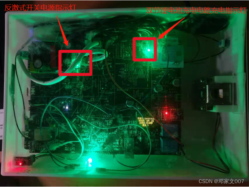


According to the above test table , Use flyback switching power supply as input power supply , The remaining power is 56% when , charge 1% The electricity needs 68 second ; The remaining power is 30% when , charge 1% The electricity needs 51 second ; The remaining power is 80% when , charge 1% The electricity needs 80 second . The above reason is that the power management chip can detect the input power supply voltage 、 Current and battery voltage to automatically switch three charging modes , So it has the function similar to the flood discharge of the dam , The higher the external water surface , The slower the flood discharge speed , In this way, the lithium battery is included . While using USB The charging analysis of power supply and solar panel power supply as input power supply is similar to that of flyback switching power supply as input power supply , It can be seen that the input power of the three input power supplies : Flyback switching power supply > Solar panel power supply >USB Power Supply , Therefore, the charging rate is affected by the input power .
So we can come to the conclusion that , The charging speed is not only related to the current battery capacity , And it is related to the power of the input power supply .
6 summary
The lower computer system of the fire hydrant monitoring system is powered and used by a variety of switching power supplies C Language to write the bottom driver to realize each functional module of the system . The upper computer of the fire hydrant monitoring system uses JAVA Android Bluetooth application written in and cloud intelligence provided by alicloud life IOT APP. The fire hydrant monitoring system is mainly used to monitor the real-time situation of outdoor fire hydrant equipment and indoor fire hydrants , It uses a water pressure sensor 、 Temperature sensor 、 Gyroscope and other sensors complete various data acquisition of the equipment , And pass NB-IOT Upload data to Alibaba cloud Internet of things server to use cloud intelligence APP View the latest data ; Android Bluetooth APP It can provide wireless short-range data transmission , It is convenient for engineers to wirelessly view the debugging output data and wirelessly unlock . After many times of debugging and modification , The fire hydrant monitoring system can be used for a long time 、 The stability of the 、 Reliable monitoring .
Advantages of fire hydrant monitoring system :
① The bottom drivers of the system are all developed with registers , Therefore, its program operation occupies less resources , Fast execution .
② It has a variety of power circuits for conversion and power supply , Ensure that the power input of the system is stable [9].
③ A variety of lithium battery charging circuits make the system compatible for long-time work indoors and outdoors .
④ Android Bluetooth APP The cooperation with Bluetooth module makes the system have comprehensive wireless short-range communication , Comprehensive supporting services facilitate engineers' outdoor commissioning 、 Maintenance work , It is more humanized .
⑤ Have a comprehensive 、 Fire hydrant monitoring system composed of perfect circuit , In addition to ensuring the stability and reliability of the system . It also reduces the cost and provides a comprehensive maintenance scheme to reduce the cost and time of maintenance .
⑥ GPS Beidou meter error positioning enables engineers to quickly 、 Accurately find the equipment to be maintained , Effectively guarantee the new 、 Old engineers can quickly hand over work .
Disadvantages of fire hydrant monitoring system :
① There is hardware in the lithium battery protection circuit BUG, Only after the negative pole of the lithium battery pack is short circuited with the circuit board ground, can the normal lithium battery power supply be carried out .
② Circuit board 12V The output power of the power output port is insufficient .
③ The system is not very stable when connected to the Alibaba cloud Internet of things platform , Sometimes the connection is unsuccessful .
④ Cloud intelligence APP On the positioning coordinate display, the intelligent display retains two decimal places .
⑤ GPS Beidou Positioning can only be carried out outdoors , That makes the indoor hydrant monitoring system only through the equipment ID To specify the fixed floor area location .
The fire hydrant monitoring system still has some functions that need to be added later , for example : add to IAP The program automatically upgrades the driver , Use Android Bluetooth APP Replace and upgrade the underlying driver of the fire hydrant monitoring system in a short wireless distance , To increase the stability and reliability of the fire hydrant monitoring system ; add to EEPROM Keep it up to date GPS Location information , prevent GPS The Beidou module is suddenly damaged and loses the positioning information, and the positioning information cannot be obtained in dark cloud intensive weather .
Through this design, we have expanded and improved our understanding of STM32 Related underlying driver development 、 Hardware circuit design 、 be based on JAVA Language development Android APP And use solidworks Software 3D Design and other capabilities , Make the development of the whole stack to a higher level .
边栏推荐
- Metaverse × How will smart cities develop?
- Force deduction solution summary 942- increase / decrease string matching
- What is SAP c/4hana Foundation
- Cvpr2022 | IFS RCNN: an incremental small sample instance splitter
- Ozzanmation action system based on SSE
- 力扣解法汇总面试题 17.11-单词距离
- el-upload上传文件
- Force deduction solution summary 883- projected area of 3D shape
- Force deduction solution summary 953 verification of alien language dictionary
- Why do we use Google search ads?
猜你喜欢
el-upload上传文件

CVPR2022 | iFS-RCNN:一种增量小样本实例分割器

How to automatically color cells in Excel

BaseDexClassLoader那些事

Almost all schools will ask for the second round exam! Come in and recite the answer!

入手Ticwatch2

The release of star ring kundb 2.2 provides a new choice for business systems with high concurrent transactions and queries

RPA introduction

Alicloud OSS file upload system

leetcode:6. Zigzag transformation
随机推荐
The most comprehensive redis transaction control in 2022 (with illustration)
力扣解法汇总面试题 01.05. 一次编辑
力扣解法汇总497-非重叠矩形中的随机点
DDD的分层架构
“中国东信杯”广西大学第四届程序设计竞赛(同步赛)
Force deduction solution summary -04.06 Successor
How WPS inserts a directory and the operating steps for quickly inserting a directory
Proxy and reflection (II)
SwiftyJSON解析本地JSON文件
高考完不要急着去打工了,打工以后有的是机会,不差这三个月
Installing MySQL version 5.5 database for Linux (centos6)
Almost all schools will ask for the second round exam! Come in and recite the answer!
Cvpr2022 | IFS RCNN: an incremental small sample instance splitter
Implementation scheme of iteration and combination pattern for general tree structure
Graphical data analysis | business analysis and data mining
Summary of force deduction method 417- Pacific Atlantic current problems
力扣编程题-解法汇总
力扣解法汇总868-二进制间距
Force deduction solution summary 388- longest absolute path of file
Ozzanmation action system based on SSE