当前位置:网站首页>Realization of LED water lamp based on C51
Realization of LED water lamp based on C51
2022-07-26 06:57:00 【Miaowu】
Preface : This experiment is based on STC89C52RC Chip integrated 51 Single chip microcomputer , Light up according to the circuit schematic led The lamp , At the same time to realize led The riding light effect of the lamp . because 51 The structure of Series MCU is similar , Readers can draw inferences from this blog , Realize the required functions .
Catalog :
- One 、 Background knowledge
- Two 、 Environment building
- 3、 ... and 、 Light up a led The lamp
- Four 、led Light flashing
- 5、 ... and 、led Running water lamp
The single chip microcomputer selected in the experiment and its structure are displayed ( In general C51 For example , The others are similar ), The operation of this experiment led The module is located in the figure ⑤ Location

Experimental results
One 、 Background knowledge
Single chip microcomputer : It's an integrated circuit chip , Is the use of VLSI technology with data processing capacity of the central processor CPU、 Ram RAM、 read-only memory ROM And other functions are integrated into a silicon chip to form a small and perfect microcomputer system 
To make the system work properly , We must ensure that the minimum system of single chip microcomputer works stably .51 SCM's most The small system consists of the following parts : (1) Crystal oscillator circuit ( Crystal oscillator circuit provides clock for single chip microcomputer to work , Like a human heart )(2) Reset circuit (3) Power circuit 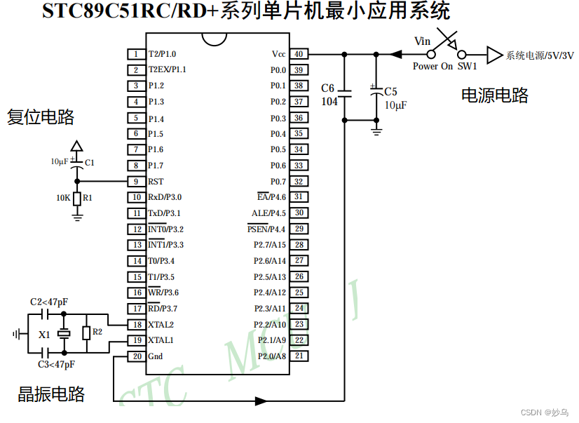
Chip pin classification :
(1) Power pin : In the picture above VCC、GND All belong to the power pin
(2) Crystal oscillator pin : In the picture above XTAL1、[email protected] All belong to crystal oscillator pins
(3) Reset pin : In the picture above RST/VPD Belongs to reset pin
(4) Communication pin :51 MCU serial port function pin (TXD、RXD)
(5)GPIO Pin : The figure above shows Px.x Such words belong to GPIO Pin , common 32 individual , It is divided into 4 Group , Each group 8 individual IO
P0 The port is open drain , To make its output high , The pull resistance must be connected externally , Usually choose 4.7K~10K resistance .
P0、P1、P2 Almost all used as ordinary I/O Mouth use , It can be used as input , It can also be used as output .
P3 The mouth can be used as a common I/O mouth , It can also be used as a second function , For example, serial port 、 External medium break 、 Counter, etc .
Two 、 Environment building (keil4)
New project -> choice CPU model (Atmel(AT89C52))-> Add files to the project -> Configuration output file hex

3、 ... and 、 Light up a led The lamp
3.1 Check the circuit schematic diagram

By observing the circuit connection diagram of the development board, we can observe :
️ 1.D1 The cathode is connected to the P2.0 Pin ( The same number of lines means they are connected P20)、D2 Connect to MCU P2.1 Pin ………
️ 2. When a single chip computer P2.0 Output low level 0, Connected to the power supply D1 Formation pathway ,D1 Light on .P2.X Output 0, The same is true of other lights .
therefore , To make D1 Equal brightness , Need to program and burn the program into the MCU , bring P2.0 Port output low level ,
3.2 Write code and burn
️ 3.2.1 Import reg52.h The header file , During precompiling, the contents of the header file will be loaded into the file ,reg52.h The contents in the header file are as follows :
#ifndef __REG52_H__
#define __REG52_H__

/*  BYTE Registers  */
sfr P0    = 0x80;
sfr P1    = 0x90;
sfr P2    = 0xA0;
sfr P3    = 0xB0;
sfr PSW   = 0xD0;
sfr ACC   = 0xE0;
sfr B     = 0xF0;
sfr SP    = 0x81;
sfr DPL   = 0x82;
sfr DPH   = 0x83;
sfr PCON  = 0x87;
sfr TCON  = 0x88;
sfr TMOD  = 0x89;
sfr TL0   = 0x8A;
sfr TL1   = 0x8B;
sfr TH0   = 0x8C;
sfr TH1   = 0x8D;
sfr IE    = 0xA8;
sfr IP    = 0xB8;
sfr SCON  = 0x98;
sfr SBUF  = 0x99;

/*  8052 Extensions  */
sfr T2CON  = 0xC8;
sfr RCAP2L = 0xCA;
sfr RCAP2H = 0xCB;
sfr TL2    = 0xCC;
sfr TH2    = 0xCD;


/*  BIT Registers  */
/*  PSW  */
sbit CY    = PSW^7;
sbit AC    = PSW^6;
sbit F0    = PSW^5;
sbit RS1   = PSW^4;
sbit RS0   = PSW^3;
sbit OV    = PSW^2;
sbit P     = PSW^0; //8052 only

/*  TCON  */
sbit TF1   = TCON^7;
sbit TR1   = TCON^6;
sbit TF0   = TCON^5;
sbit TR0   = TCON^4;
sbit IE1   = TCON^3;
sbit IT1   = TCON^2;
sbit IE0   = TCON^1;
sbit IT0   = TCON^0;

/*  IE  */
sbit EA    = IE^7;
sbit ET2   = IE^5; //8052 only
sbit ES    = IE^4;
sbit ET1   = IE^3;
sbit EX1   = IE^2;
sbit ET0   = IE^1;
sbit EX0   = IE^0;

/*  IP  */
sbit PT2   = IP^5;
sbit PS    = IP^4;
sbit PT1   = IP^3;
sbit PX1   = IP^2;
sbit PT0   = IP^1;
sbit PX0   = IP^0;

/*  P3  */
sbit RD    = P3^7;
sbit WR    = P3^6;
sbit T1    = P3^5;
sbit T0    = P3^4;
sbit INT1  = P3^3;
sbit INT0  = P3^2;
sbit TXD   = P3^1;
sbit RXD   = P3^0;

/*  SCON  */
sbit SM0   = SCON^7;
sbit SM1   = SCON^6;
sbit SM2   = SCON^5;
sbit REN   = SCON^4;
sbit TB8   = SCON^3;
sbit RB8   = SCON^2;
sbit TI    = SCON^1;
sbit RI    = SCON^0;

/*  P1  */
sbit T2EX  = P1^1; // 8052 only
sbit T2    = P1^0; // 8052 only

/*  T2CON  */
sbit TF2    = T2CON^7;
sbit EXF2   = T2CON^6;
sbit RCLK   = T2CON^5;
sbit TCLK   = T2CON^4;
sbit EXEN2  = T2CON^3;
sbit TR2    = T2CON^2;
sbit C_T2   = T2CON^1;
sbit CP_RL2 = T2CON^0;

#endif
You can see this in the code above , The header file defines 52 All internal functions of series single chip microcomputer register . among sbit、sfr by C51 Extended data type .C51 The main types of extended data are as follows :
ssfr P2 = 0xA0;
Make a statement 8 Bit special function register , It starts at 0xA0
sbit LED1 = P2^0
P2 It's a 8 Bit register ,P2^0 Express this 8 The lowest bit of the bit register . The function of this statement is to P2 The lowest bit of the register is declared as LED1, If you want to be right in the future P2 Register lowest bit operation , Can be operated directly LED1
️ 3.2.2 Programming
Use while(1) Dead cycle , Keep the program running , This will guarantee led The light stays on .
main.c
#include "reg52.h"

sbit LED1=P2^0;	// take P2.0 Pins are defined as LED1

void main()
{
	LED1=0;	// Register P2 The lowest bit of is low
	while(1)
	{

	}
}
Four 、 Realization led Light flashing
When a single chip computer P2.0 Pin output high level ,led Wait for no potential difference on both sides , So no current flows ,led The light goes out . The implementation procedure is as follows :
#include "reg52.h"

typedef unsigned int u16;	// Redefine the default data type of the system
typedef unsigned char u8;

sbit LED1=P2^0;	// take P2.0 Pins are defined as LED1

/*******************************************************************************
* Function name       : delay_10us
*  The functionality 		 :  The time delay function ,ten_us=1 when , About time delay 10us
*******************************************************************************/
void delay_10us(u16 ten_us)
{
	while(ten_us--);
}

void main()
{
	while(1)
	{
		LED1=0;	// Lighten up
		delay_10us(50000); // Lighten up 500ms
		LED1=1;	// Extinguish
		delay_10us(50000);
	}
}
5、 ... and 、 Realization led Running water lamp
This experiment is realized in two ways led Lantern effect , One is through circulation + Shift completion pair P2 Each bit of the register is assigned a low level in turn . The second is to use intrins,h External methods defined in the header file _crol_ And _cror_ Realize bitwise movement respectively
#include "reg52.h"
#include "intrins.h"

typedef unsigned int u16;	// Redefine the default data type of the system
typedef unsigned char u8;

#define LED_PORT	P2	// Use a macro to define P2 Port registers

/*******************************************************************************
*  Function name :       : delay_10us
*  The functionality 		 :  The time delay function ,ten_us=1 when , About time delay 10us
*******************************************************************************/
void delay_10us(u16 ten_us)
{
	while(ten_us--);
}

void main()
{
   	u8 i=0;

	LED_PORT=~0x01;	// to P2 Register bit assignment , That is, assign a low level to the lowest bit of the register
	delay_10us(50000);
	while(1)
	{
		// Mode one : By shifting + Cycle to realize water lamp
				for(i=0;i<8;i++)
		{
			LED_PORT=~(0x01<<i);	// to P2 Register low level from the lowest to the highest , loop 8 Continue the cycle after times
			delay_10us(50000);
		}

		// The way 2: Using a loop +_crol_ or _cror_ Function to realize water lamp
//		for(i=0;i<7;i++)	 // take led The left one
//		{
//			LED_PORT=_crol_(LED_PORT,1);
//			delay_10us(50000);
//		}
//		for(i=0;i<7;i++)	// take led Moves to the right one
//		{
//			LED_PORT=_cror_(LED_PORT,1);
//			delay_10us(50000);
//		}
	}
}
Thank you for watching. , If you have doubts or supplements about the content , Feel free to leave a comment , Common progress !!!

边栏推荐
猜你喜欢

7. Reverse Integer整数反转

Can you learn fast and well with dual stream network? Harbin Institute of Technology & Microsoft proposed a distillation dual encoder model for visual language understanding, which can achieve fast an

The results of the soft test can be checked, and the entry to query the results of the soft test has been opened in the first half of 2022

在第一次使用德国小鸡要注意的地方

哈夫曼编码原理

Rectification ideas for the previous article

Binary tree knowledge summary

CS5801_ HDMI to EDP advantage replaces lt6711a solution

【硬十宝典】——7.1【动态RAM】DDR硬件设计要点
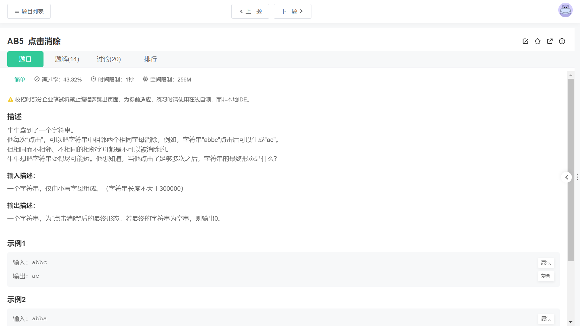
Click "Niuke | daily question" to eliminate it
随机推荐
『HarmonyOS』工程的创建与虚拟机的使用
How to solve the crash when the easygbs platform edits the device management group?
Huffman coding principle
Vim中删除^M
< II> ObjectARX development: create and edit basic graphic objects
Function of hot air pad
mysql优化之show profile的使用及分析
SQL shell (PSQL) tool under PostgreSQL
Leetcode question brushing 1: topic classification
buuReserve(4)
在第一次使用德国小鸡要注意的地方
Differences and relations between varchar and nvarchar in database
Press in and pop-up sequence of "Niuke | daily question" stack
CS5801_ HDMI to EDP advantage replaces lt6711a solution
Exclusive lock
『牛客|每日一题』 栈的压入、弹出序列
mySql建表的基本操作 与常见的函数
Go language configuration vscade
"Niuke | daily question" inverse Polish expression
Queue assistant | product update log in June 2022