当前位置:网站首页>Pandora IOT development board learning (RT thread) - Experiment 2 RGB LED experiment (learning notes)
Pandora IOT development board learning (RT thread) - Experiment 2 RGB LED experiment (learning notes)
2022-07-02 16:07:00 【Xiaohui_ Super】
This article code reference RT-Thread official BSP
List of articles
Experimental function
Routine source code :(main.c)
The experiment realized RGB The lamp 8 Switching between States , Switching interval is 500 ms.
/* * Copyright (c) 2006-2018, RT-Thread Development Team * * SPDX-License-Identifier: Apache-2.0 * * Change Logs: * Date Author Notes * 2018-08-22 balanceTWK first implementation */

#include <rtthread.h>
#include <rtdevice.h>
#include <board.h>

#define DBG_TAG "main"
#define DBG_LVL DBG_LOG
#include <rtdbg.h>

/*  Definition  LED  On off level  */
#define LED_ON (0)
#define LED_OFF (1)

/*  Definition  8  Group  LED  Flash meter , The order is  R G B */
static const rt_uint8_t _blink_tab[][3] =
{

    {
    LED_ON, LED_ON, LED_ON},
    {
    LED_OFF, LED_ON, LED_ON},
    {
    LED_ON, LED_OFF, LED_ON},
    {
    LED_ON, LED_ON, LED_OFF},
    {
    LED_OFF, LED_OFF, LED_ON},
    {
    LED_ON, LED_OFF, LED_OFF},
    {
    LED_OFF, LED_ON, LED_OFF},
    {
    LED_OFF, LED_OFF, LED_OFF},
};

int main(void)
{

    unsigned int count = 1;
    unsigned int group_num = sizeof(_blink_tab)/sizeof(_blink_tab[0]);
    unsigned int group_current;

    /*  Set up  RGB  The lamp pin is in output mode  */
    rt_pin_mode(PIN_LED_R, PIN_MODE_OUTPUT);
    rt_pin_mode(PIN_LED_G, PIN_MODE_OUTPUT);
    rt_pin_mode(PIN_LED_B, PIN_MODE_OUTPUT);

    while (count > 0)
    {

        /*  Get group number  */
        group_current = count % group_num;

        /*  control  RGB  The lamp  */
        rt_pin_write(PIN_LED_R, _blink_tab[group_current][0]);
        rt_pin_write(PIN_LED_G, _blink_tab[group_current][1]);
        rt_pin_write(PIN_LED_B, _blink_tab[group_current][2]);

        /*  Output  LOG  Information  */
        LOG_D("group: %d | red led [%-3.3s] | green led [%-3.3s] | blue led [%-3.3s]",
            group_current,
            _blink_tab[group_current][0] == LED_ON ? "ON" : "OFF",
            _blink_tab[group_current][1] == LED_ON ? "ON" : "OFF",
            _blink_tab[group_current][2] == LED_ON ? "ON" : "OFF");

        /*  Delay for a period of time  */
        rt_thread_mdelay(500);
        count++;
    }
    return 0;
}
Code analysis
rt_pin_mode()
The function is to GPIO Pin The initialization , Defined as
/* RT-Thread Hardware PIN APIs */
void rt_pin_mode(rt_base_t pin, rt_base_t mode)
{

    RT_ASSERT(_hw_pin.ops != RT_NULL);
    _hw_pin.ops->pin_mode(&_hw_pin.parent, pin, mode);
}
Parameters pin It's a rt_base_t Variable (long), Below GET_PIN() yes STM32 Of pin Value macro definition , Fill in capital letters for the first parameter , The second parameter is filled with numbers .
#define GET_PIN(PORTx,PIN) (rt_base_t)((16 * ( ((rt_base_t)__STM32_PORT(PORTx) - (rt_base_t)GPIOA)/(0x0400UL) )) + PIN)

#define __STM32_PORT(port) GPIO##port // ##  Is a character connector , If  port  by  A, said  GPIOA
For example, in the experiment
#define PIN_LED_R GET_PIN(E, 7), Express GPIOE GPIO_Pin7
at present RT-Thread Supported pin operating modes include :
#define PIN_MODE_OUTPUT 0x00 /*  Output  */
#define PIN_MODE_INPUT 0x01 /*  Input  */
#define PIN_MODE_INPUT_PULLUP 0x02 /*  Pull up input  */
#define PIN_MODE_INPUT_PULLDOWN 0x03 /*  Drop down input  */
#define PIN_MODE_OUTPUT_OD 0x04 /*  Open drain output  */
stay bsp Of drv_gpio.c In file , There is a bottom layer GPIO drive , Here is STM32 Of GPIO Driver function of mode setting ( You should be familiar with , Just use HAL Library written GPIO Initialization code )
static void stm32_pin_mode(rt_device_t dev, rt_base_t pin, rt_base_t mode)
{

    const struct pin_index *index;
    GPIO_InitTypeDef GPIO_InitStruct;

    index = get_pin(pin);
    if (index == RT_NULL)
    {

        return;
    }

    /* Configure GPIO_InitStructure */
    GPIO_InitStruct.Pin = index->pin;
    GPIO_InitStruct.Mode = GPIO_MODE_OUTPUT_PP;
    GPIO_InitStruct.Pull = GPIO_NOPULL;
    GPIO_InitStruct.Speed = GPIO_SPEED_FREQ_HIGH;

    if (mode == PIN_MODE_OUTPUT)
    {

        /* output setting */
        GPIO_InitStruct.Mode = GPIO_MODE_OUTPUT_PP;
        GPIO_InitStruct.Pull = GPIO_NOPULL;
    }
    else if (mode == PIN_MODE_INPUT)
    {

        /* input setting: not pull. */
        GPIO_InitStruct.Mode = GPIO_MODE_INPUT;
        GPIO_InitStruct.Pull = GPIO_NOPULL;
    }
    else if (mode == PIN_MODE_INPUT_PULLUP)
    {

        /* input setting: pull up. */
        GPIO_InitStruct.Mode = GPIO_MODE_INPUT;
        GPIO_InitStruct.Pull = GPIO_PULLUP;
    }
    else if (mode == PIN_MODE_INPUT_PULLDOWN)
    {

        /* input setting: pull down. */
        GPIO_InitStruct.Mode = GPIO_MODE_INPUT;
        GPIO_InitStruct.Pull = GPIO_PULLDOWN;
    }
    else if (mode == PIN_MODE_OUTPUT_OD)
    {

        /* output setting: od. */
        GPIO_InitStruct.Mode = GPIO_MODE_OUTPUT_OD;
        GPIO_InitStruct.Pull = GPIO_NOPULL;
    }

    HAL_GPIO_Init(index->gpio, &GPIO_InitStruct);
}
rt_pin_write()
GPIO Write function , Here is the definition of the function ,
void rt_pin_write(rt_base_t pin, rt_base_t value)
{

    RT_ASSERT(_hw_pin.ops != RT_NULL);
    _hw_pin.ops->pin_write(&_hw_pin.parent, pin, value);
}
and GPIO The mode configuration function is similar , In fact, it will also call the corresponding functions in the underlying driver , The underlying function is through HAL_GPIO_WritePin() To complete GPIO Pin Modification of .
static void stm32_pin_write(rt_device_t dev, rt_base_t pin, rt_base_t value)
{

    const struct pin_index *index;

    index = get_pin(pin);
    if (index == RT_NULL)
    {

        return;
    }

    HAL_GPIO_WritePin(index->gpio, index->pin, (GPIO_PinState)value);
}
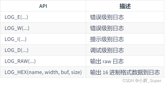
LOG_D()
In this study , We can LOG_D() As rt_kprintf(),
#define dbg_log_line(lvl, color_n, fmt, ...) \ do \ {
       \ _DBG_LOG_HDR(lvl, color_n); \ rt_kprintf(fmt, ##__VA_ARGS__); \ _DBG_LOG_X_END; \ } \ while (0)
LOG_D yes RT-Thread A log printing function in the kernel , Details visible :《RT-Thread Document center ——ulog journal 》
RT-Thread Log API Include :
rt_thread_mdelay()
This is a RT-Thread Millisecond delay function , The definition is as follows :
rt_err_t rt_thread_mdelay(rt_int32_t ms)
{

    rt_tick_t tick;

	//  Get the required clock beat
    tick = rt_tick_from_millisecond(ms);

	//  Block the corresponding beat time
    return rt_thread_sleep(tick);
}
rt_tick_from_millisecond()
/** *  Work out  ms  The number of corresponding clock beats  * * * @param ms the specified millisecond * - Negative Number wait forever * - Zero not wait * - Max 0x7fffffff * * @return the calculated tick */
rt_tick_t rt_tick_from_millisecond(rt_int32_t ms)
{

    rt_tick_t tick;

    if (ms < 0)
    {

        tick = (rt_tick_t)RT_WAITING_FOREVER;  // -1
    }
    else
    {

    	//  take “ Beats per second ” / 1000 * ms, Calculate the corresponding second beats
        tick = RT_TICK_PER_SECOND * (ms / 1000);

		//  Plus less than  1000ms  Part of the beat number
        tick += (RT_TICK_PER_SECOND * (ms % 1000) + 999) / 1000;
    }

    /* return the calculated tick */
    return tick;
}
rt_thread_sleep()
Thread sleep ( Hang up ) function , The parameter is the number of system beats :
/** *  This function can make the current thread hang for a period of time ( from  tick  decision ) * * @param tick the sleep ticks * * @return RT_EOK */
rt_err_t rt_thread_sleep(rt_tick_t tick)
{

    register rt_base_t temp;
    struct rt_thread *thread;

    /* set to current thread */
    thread = rt_thread_self();
    RT_ASSERT(thread != RT_NULL);
    RT_ASSERT(rt_object_get_type((rt_object_t)thread) == RT_Object_Class_Thread);

    /* disable interrupt */
    temp = rt_hw_interrupt_disable();

    /* suspend thread */
    rt_thread_suspend(thread);

    /* reset the timeout of thread timer and start it */
    rt_timer_control(&(thread->thread_timer), RT_TIMER_CTRL_SET_TIME, &tick);
    rt_timer_start(&(thread->thread_timer));

    /* enable interrupt */
    rt_hw_interrupt_enable(temp);

    rt_schedule();

    /* clear error number of this thread to RT_EOK */
    if (thread->error == -RT_ETIMEOUT)
        thread->error = RT_EOK;

    return RT_EOK;
}
边栏推荐
- 原神2.6服务端下载以及搭建安装教程
- Boot connection to impala database
- 构建多架构镜像的最佳实践
- Analysis of the difference between array and linked list
- Wavedec2 in MATLAB, talk about the wavedec2 function [easy to understand]
- /Bin/ld: cannot find -llz4
- JS learning notes - variables
- C # get PLC information (kepserver) II
- Postgressql stream replication active / standby switchover primary database no read / write downtime scenario
- Astra: could not open "2bc5/ [email protected] /6“: Failed to set USB interface
猜你喜欢

中科大脑知识图谱平台建设及业务实践

结构体的内存对齐

Mobile web development learning notes - Layout

华为云服务器安装mysqlb for mysqld.service failed because the control process exited with error code.See “sys
如何实现十亿级离线 CSV 导入 Nebula Graph
Figure database | Nepal graph v3.1.0 performance report

The outline dimension function application of small motherboard

Why does the system convert the temp environment variable to a short file name?

Experiment collection of University "Fundamentals of circuit analysis". Experiment 6 - observation and measurement of typical signals

隐藏在 Nebula Graph 背后的星辰大海
随机推荐
Add user-defined formula (time sharing t+0) to mobile app access as an example
HMS core machine learning service helps zaful users to shop conveniently
/Bin/ld: cannot find -lssl
Solve the problem of base64encoder error
Boot 中bean配置覆盖
Soul torture, what is AQS???
Experiment collection of University "Fundamentals of circuit analysis". Experiment 6 - observation and measurement of typical signals
Use ffmpeg command line to push UDP and RTP streams (H264 and TS), and ffplay receives
死锁的条件及解决方法
去除router-link中的下划线
Traversal before, during and after binary tree
Group by的用法
《大学“电路分析基础”课程实验合集.实验四》丨线性电路特性的研究
Armv8-a programming guide MMU (4)
源码look me
Bean configuration override in boot
Pyobject to char* (string)
Application of visualization technology in Nebula graph
How to import a billion level offline CSV into Nepal graph
Solve * * warning * *: your ApplicationContext is unlikely to start due to a @componentscan of the defau