当前位置:网站首页>STM32F103 realize IAP online upgrade application
STM32F103 realize IAP online upgrade application
2022-07-07 04:54:00 【Hua Weiyun】
One 、 Introduction to the environment
MCU: STM32F103ZET6
Programming IDE: Keil5.25
Two 、 IAP Introduce
IAP, The full name is “In-Application Programming”, The Chinese explanation is “ To program in a program ”.IAP It is an external interface through microcontroller ( Such as USART,IIC,CAN,USB, Ethernet interface and even radio frequency channel ) The technology of updating the internal program of the microcontroller running the program ( Note that this is completely different from ICP perhaps ISP technology ).
ICP(In-Circuit Programming) Technology is to burn the program of single chip microcomputer through online simulator , and ISP Technology is built-in through MCU bootloader Program guided burning technology . Whether it's ICP Technology or ISP technology , All need mechanical operations, such as connecting the download line , Set jumper cap, etc . If the circuit board of the product has been sealed in the shell layer by layer , It is undoubtedly difficult to update its program , If the product is installed in a narrow space and other inaccessible places , It was a disaster . But if you introduce IAP technology , Can completely avoid the above embarrassing situation , Moreover, if a long-distance or wireless data transmission scheme is used , It can even realize remote programming and wireless programming . This is absolutely ICP or ISP What technology can't do . Some kind of microcontroller supports IAP The first premise of technology is that it must be a microcontroller based on reprogrammable flash memory .STM32 The microcontroller has a programmable built-in flash memory , meanwhile STM32 It has abundant peripheral communication interfaces in quantity and types , So in STM32 Implemented on IAP The technology is completely feasible .
Realization IAP The core of the technology is a section of pre written in the MCU IAP Program . This program is mainly responsible for handshake synchronization with external host computer software , Then the program data from the upper computer software is received through the peripheral communication interface and written into the flash memory area specified in the MCU , Then jump to execute the newly written program , Finally, the purpose of program update is achieved .
stay STM32 Implemented on a microcontroller IAP Before the procedure, first review STM32 Internal flash organizational structure and its startup process .STM32 The internal flash address of starts at 0x8000000, In general , Program files are written from this address . Besides STM32 Is based on Cortex-M3 Microcontrollers in the kernel , It passes through a “ Interrupt vector table ” In response to the interruption , After the program starts , Will start with “ Interrupt vector table ” Take out the reset interrupt vector and execute the reset interrupt program to complete the startup . And this one “ Interrupt vector table ” The starting address of is 0x8000004, When the interruption comes ,STM32 The internal hardware mechanism will also automatically PC The pointer is positioned to “ Interrupt vector table ” It's about , According to the interrupt source, the corresponding interrupt vector is taken out to execute the interrupt service program . Finally, you need to know the key point , By modifying the STM32 The link script of the project can modify the starting address of the program file written to the flash memory .
stay STM32 Implemented on a microcontroller IAP programme , In addition to conventional operations such as receiving data through serial port and writing flash data , Attention is also needed STM32 Startup process and interrupt response mode .
The image below shows STM32 Routine operation process :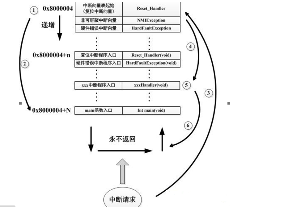
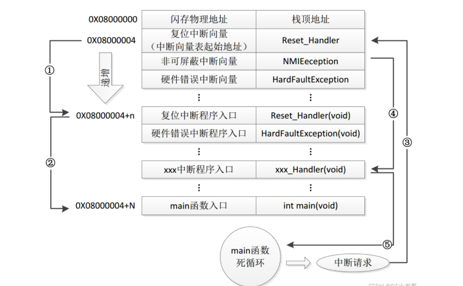
The diagram reads as follows :
1、 STM32 After reset , From the address 0x8000004 Take out the address of reset interrupt vector , And jump to execute the reset interrupt service program .
2、 The final result of the reset interrupt service program execution is to jump to C programmatic main function , and main The function should be an endless loop , Is a function that never returns .
3、 stay main During the execution of the function , An interrupt request has occurred , here STM32 The hardware mechanism will PC The pointer forcibly refers back to the interrupt vector table .
4、 Enter the corresponding interrupt service program according to the interrupt source .
5、 After the interrupt service program is executed , The program returns to main Execute in function .
If in STM32 Added IAP Program :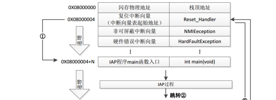
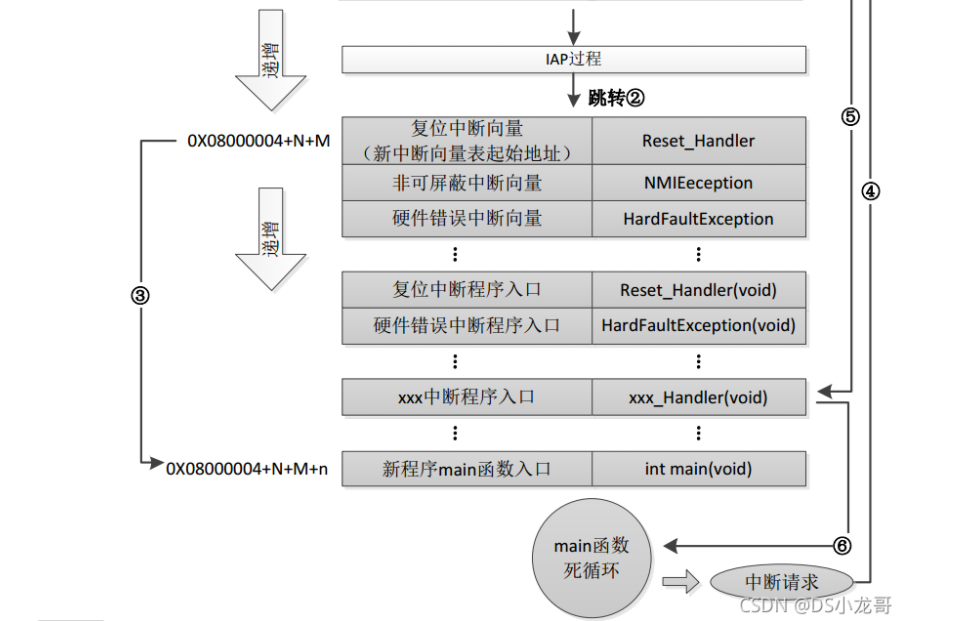
1、 STM32 After reset , From the address of 0x8000004 Take out the address of reset interrupt vector , And jump to execute the reset interrupt service program , Then jump to IAP programmatic main function .
2、 After execution IAP After the process (STM32 There are many new programs written inside , The address begins with 0x8000004+N+M) Jump to the reset vector table of the new writer , Take out the address of the reset interrupt vector of the new program , And jump to execute the new program reset interrupt service program , Then jump to the main function . Of the new program main Functions should also have the property of never returning . At the same time, we should pay attention to STM32 The internal storage space of appears in different locations 2 An interrupt vector table .
3、 In the new program main During the execution of the function , An interrupt request is coming ,PC The pointer will still turn to the address 0x8000004 At the interrupt vector table , Not the interrupt vector table of the new program , Notice that this is caused by STM32 The hardware mechanism determines .
4、 Jump to the corresponding interrupt service according to the interrupt source , Note that this is a jump to the interrupt service program of the new program .
5、 After the execution of the interrupt service , return main function .
Two 、hex File with the bin File differences
Intel HEX A file is a record of text lines ASCII text file , stay Intel HEX In file , Each row is one HEX Record , A machine code or data constant consisting of hexadecimal numbers .Intel HEX Files are often used to transfer and store programs or data to ROM、EPROM, Most programmers and simulators use Intel HEX file .
Many compilers support generation HEX Format of the burning file , In especial Keil c. But what programmers can download is often BIN Format , therefore HEX turn BIN Is a function that every programmer must support .HEX Format files are in behavioral units , Each line by “:”(0x3a) Start , End with enter (0x0d,0x0a). The data in a row is represented by two characters 16 Hexadecimal bytes , such as ”01” It means number 0x01;”0a”, It means 0x0a. about 16 Address of bit , Then the high is in the front and the low is in the back , Like the address 0x010a, stay HEX The format file is represented as a string ”010a”.hex and bin File format
Hex file , This means Intel Standard hexadecimal file , That is, the hexadecimal form of machine code , And it is in a certain file format ASCII Code to represent . The specific format is as follows : Intel hex File is often used to save the target program code of MCU or other processors . It holds the object code image in the physical program store . General programmers support this format . hex and bin File format Hex file , This means Intel Standard hexadecimal file , That is, the hexadecimal form of machine code , And it is in a certain file format ASCII Code to represent . The specific format is as follows : Intel hex File is often used to save the target program code of MCU or other processors . It holds the object code image in the physical program store . General programmers support this format .
3、 ... and 、 Use Keil Software complete hex File transfer bin file
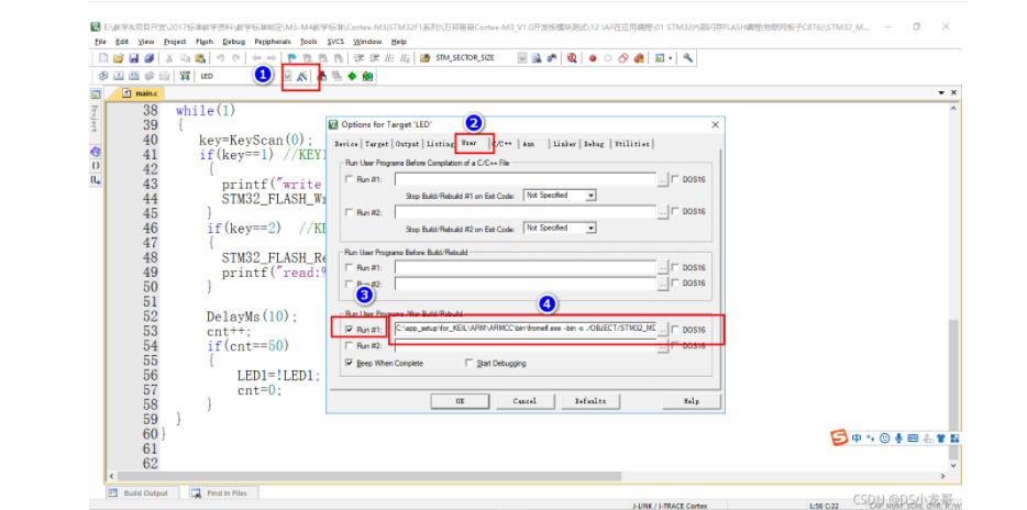
The code in the option box :
C:\app_setup\for_KEIL\ARM\ARMCC\bin\fromelf.exe --bin -o ./OBJECT/STM32_MD.bin ./OBJECT/STM32_MD.axf
The analysis is as follows :
C:\app_setup\for_KEIL\ARM\ARMCC\bin\fromelf.exe: yes keil A tool in the software installation directory , Used to generate bin
–bin -o ./OBJECT/STM32_MD.bin : Specify generation bin Directory and name of the file
./OBJECT/STM32_MD.axf : Specify the input file . Generate hex Documentation needs axf file
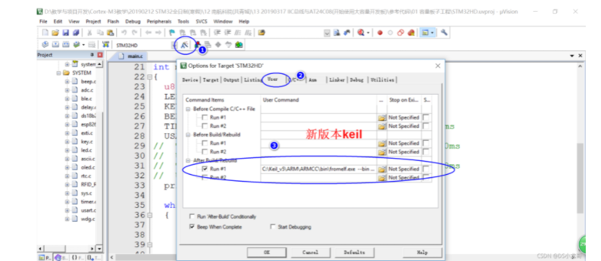
Compilation instructions for new projects :
C:\Keil_v5\ARM\ARMCC\bin\fromelf.exe --bin -o ./obj/STM32HD.bin ./obj/STM32HD.axf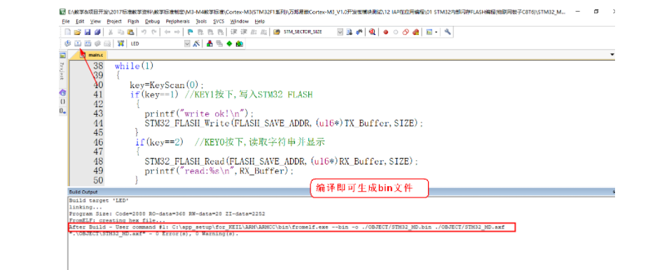

Download the file to STM32 built-in FLASH, Reset the development board , You can start the program .
Four 、 Use win hex The software will bin Make the file into an array
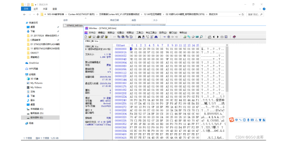
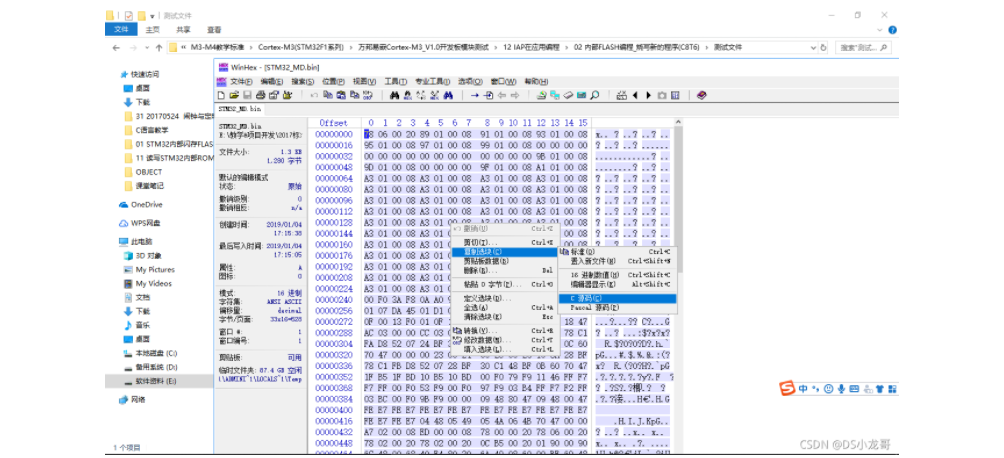
After generating the array , You can directly compile the array into the program , And then use STM32 built-in FLASH Programming code , Burn the program to the built-in FLASH in , Then reset the development board to run the new program .
5、 ... and 、 Keil Compiler size calculation
Program Size: Code=x RO-data=x RW-data=x ZI-data=x The meaning of
Code( Code ): The time occupied by the program FLASH size , Stored in FLASH.
\2. RO-data( Read only data ): Read-only-data, Program defined constants , Such as const type , Stored in FLASH in .
\3. RW-data( With initial value requirements 、 Readable and writable data ):
\4. Read-write-data, Variables that have been initialized , Stored in FLASH in . On initialization RW-data from flash copy to SRAM.
\5. ZI-data:Zero-Init-data, Uninitialized read / write variables , Stored in SRAM in .ZI-data It won't be counted in the code because it won't be initialized .
ROM(Flash) size = Code + RO-data + RW-data;
RAM size = RW-data + ZI-data
In short, when burning, it is FLASH The occupied space in is :Code+RO Data+RW Data
While the program is running , Inside the chip RAM The space used is : RW Data + ZI Data
6、 ... and 、 View project compilation information and stack information
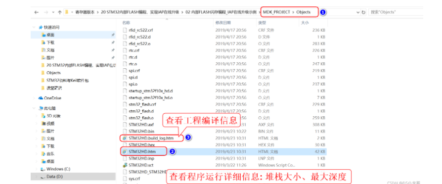
For no OS The program , The stack size is in startup.s In the setting of : Stack_Size EQU 0x00000800
For use uCos The system of ,OS The stack with its own tasks , stay os_cfg.h It defines :
/* ——————— TASK STACK SIZE ———————- */ #define OS_TASK_TMR_STK_SIZE 128 /* Timer task stack size (# of OS_STK wide entries) */#define OS_TASK_STAT_STK_SIZE 128 /* Statistics task stack size (# of OS_STK wide entries) */ #define OS_TASK_IDLE_STK_SIZE 128 /* Idle task stack size (# of OS_STK wide entries) */ The task stack of the user program , stay app_cfg.h It defines :
#define APP_TASK_MANAGER_STK_SIZE 512 #define APP_TASK_GSM_STK_SIZE 512 #define APP_TASK_OBD_STK_SIZE 512 #define OS_PROBE_TASK_STK_SIZE 128 summary :
1, It's important to set the stack properly
2, A combination of methods , Check each other 、 check
3, Try to avoid large arrays , If you must use , Try to define it as Global variables , So that it doesn't take up stack space , If the function has the possibility of reentry , Pay attention to protection .
7、 ... and 、 Realization STM32 Online upgrade program
7.1 Ideas and steps for upgrading
\1. First you have to finish STM32 built-in FLASH Programming operations
\2. take ( Upgraded program ) The new program compiles and generates bin file ( Before compiling, you need to Keil Set in the software FLASH Starting position )
\3. Create a dedicated for upgrade boot Program (IAP Bootloader)
\4. Use the Internet 、 A serial port 、SD Receive... By card, etc bin file , then bin The document burns to write STM32 built-in FLASH in
\5. Set the main stack pointer
\6. The second word in the user code area ( The first 4**** Bytes ) Is the program start address ( Force to function pointer )
\7. Execute function , Program jump
7.2 Program to be upgraded FLASH Start setting
Bootloader The program size of is fixed to : 20KB, It's better to be as small as possible , You can reserve more space for APP Program usage .
20KB----->20480Byte-----> 0x5000
STM32 built-in FLASH The starting address of flash memory is : 0x08000000 , Size is 512KB.
Will now be built in FLASH Before flash 20KB Leave room for Bootloader Program usage , The remaining space in the back is for APP Program usage .
APP The starting position of the program can be set to : 0x08000000+ 0x5000=0x08005000 The remaining size is : 512KB-20KB=492KB------>503808Byte-------->0x7B000
Set up FLASH Starting position (APP The main program ):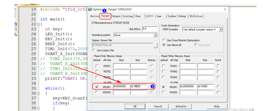
Interrupt vector table offset setting 
Set up compilation bin file 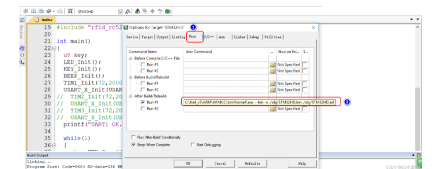

7.3 Bootloader Program settings
// Set the address to write , Must be even , Because data is read and written according to 2 Bytes #define FLASH_APP_ADDR 0x08005000 // The application is stored in FLASH Starting address in int main(){ printf("UART1 OK.....\n");printf(" Get into IAP Bootloader Program !\n"); while(1) { key=KEY_Scanf(); if(key==1) //KEY1 Press down , write in STM32 FLASH { printf(" Updating IAP Program ...............\n"); iap_write_appbin(FLASH_APP_ADDR,(u8*)app_bin_data,sizeof(app_bin_data));// Burn a new program into the built-in FLASH printf(" Program update succeeded ....\n"); iap_load_app(FLASH_APP_ADDR);// perform FLASH APP Code } }}/* The functionality : Jump to application segment appxaddr: User code start address .*/typedef void (*iap_function)(void); // Define the parameters of a function type . void IAP_LoadApp(u32 app_addr){ // Assign a legal address to the function pointer jump2app=(iap_function)*(vu32*)(app_addr+4);// The second word in the user code area is the program start address ( Reset address ) __set_MSP(*(vu32*)app_addr); // Set the main stack pointer jump2app(); // Jump to APP.}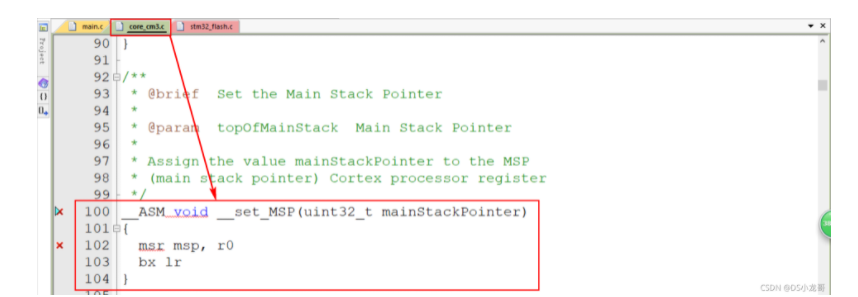
边栏推荐
- Basic idea of counting and sorting
- 未婚夫捐5亿美元给女PI,让她不用申请项目,招150位科学家,安心做科研!
- A simple and beautiful regression table is produced in one line of code~
- Flex layout and usage
- Deeply cultivate the developer ecosystem, accelerate the innovation and development of AI industry, and Intel brings many partners together
- JS variable case
- Fiance donated 500million dollars to female PI, so that she didn't need to apply for projects, recruited 150 scientists, and did scientific research at ease!
- Chapter 9 Yunji datacanvas company won the highest honor of the "fifth digital finance innovation competition"!
- Run the command once per second in Bash- Run command every second in Bash?
- STM32 system timer flashing LED
猜你喜欢
5G VoNR+之IMS Data Channel概念
Programmers go to work fishing, so play high-end!

九章云极DataCanvas公司摘获「第五届数字金融创新大赛」最高荣誉!

Tree map: tree view - draw covid-19 array diagram
Common methods of list and map

九章云极DataCanvas公司获评36氪「最受投资人关注的硬核科技企业」

为什么很多人对技术债务产生误解
01机器学习相关规定

Break the memory wall with CPU scheme? Learn from PayPal to expand the capacity of aoteng, and the volume of missed fraud transactions can be reduced to 1/30

Windows are not cheap things
随机推荐
JS variable plus
What is JVM? What are the purposes of JVM tuning?
A simple and beautiful regression table is produced in one line of code~
Depth first traversal template principle of tree and graph
过气光刻机也不能卖给中国!美国无理施压荷兰ASML,国产芯片再遭打压
【Android Kotlin协程】利用CoroutineContext实现网络请求失败后重试逻辑
JS input and output
微信能开小号了,拼多多“砍一刀”被判侵权,字节VR设备出货量全球第二,今日更多大新闻在此
How does vscade use the built-in browser?
Wechat can play the trumpet. Pinduoduo was found guilty of infringement. The shipment of byte VR equipment ranks second in the world. Today, more big news is here
Common Oracle SQL statements
赠票速抢|行业大咖纵论软件的质量与效能 QECon大会来啦
3GPP信道模型路损基础知识
Comment les tests de logiciels sont - ils effectués sur le site Web? Testez la stratégie!
Introduction to the PureMVC series
Gavin teacher's perception of transformer live class - rasa project actual combat e-commerce retail customer service intelligent business dialogue robot microservice code analysis and dialogue experim
jvm是什么?jvm调优有哪些目的?
九章云极DataCanvas公司获评36氪「最受投资人关注的硬核科技企业」
抖音或将推出独立种草社区平台:会不会成为第二个小红书
Camera calibration (I): robot hand eye calibration