当前位置:网站首页>Camera calibration (I): robot hand eye calibration
Camera calibration (I): robot hand eye calibration
2022-07-07 04:35:00 【Oak China】
hello, Hello everyone , Here is OAK China , I'm your assistant .
Recently, many friends have asked to use OAK Do robot projects , The assistant Jun happened to see this excellent article , Share with you . notes : This article has been obtained from the author @ Zhang Fuen authorized the reprint , original text Address .
Camera calibration is a very important step in robot vision , It can help the robot convert the recognized visual information , So as to complete the follow-up control work , For example, visual capture and so on . The author has done some robot hand eye calibration work , Here, the process of robot hand eye calibration is described in as simple language as possible . The purpose of this paper is to let everyone have a perceptual understanding of camera calibration , Be able to know the process of robot hand eye calibration under different conditions , The specific implementation method and technical details need to be determined by ourselves google.
1. General method of coordinate system calibration
Robot hand eye calibration is actually the calibration of the conversion relationship between two coordinate systems . Suppose there are now two coordinate systems robot and camera, And we know the corresponding fixed points P The coordinates in these two coordinate systems robotP and cameraP . Then according to the coordinate system conversion formula , We can get :
[1] robotP = robotTcameracameraP
In the above formula robotTcamera It represents the conversion matrix from camera to robot that we hope to find . robotP and cameraP To make up for 1 After “ Homogeneous coordinates ”: [x,y,z,1]T, So our homogeneous coordinate transformation matrix robotTcamera You can include both rotation and translation .
Students who have studied linear algebra should know , type [1] It's equivalent to a N The first-order equation of variables , Just order it P The number of points is larger than the dimension of the transformation matrix we solve, and these points are linearly uncorrelated , We can calculate it from the pseudo inverse matrix robotTcamera :
[2] robotTcamera = robotP(cameraP)-1
The calculated coordinate transformation matrix can be directly applied to the subsequent coordinate transformation . Now the calculated matrix allows the coordinates to rotate , translation , And zoom in any direction . If you want to turn this coordinate matrix into a rigid transformation matrix , Just orthogonalize the rotation matrix in the upper left corner , However, adding this constraint may reduce the accuracy of coordinate transformation , That is, there are too many constraints on the rigid transformation matrix , Cause under fitting .
When there is a nonlinear transformation in the coordinate transformation , We can also design and train a neural network Tnet Directly fit the relationship between the two sets of coordinates :
[3] robotP =Tnet (cameraP)
Of course, in general , type [2] The linear matrix in is enough to describe the coordinate transformation relationship between the robot and the camera . Neural network is introduced for nonlinear fitting , The fitting accuracy of the training set will be very high , But when the number of training points is insufficient , It will happen , The fitting accuracy is reduced in the actual test .
Through the above calculation, we can know , As long as we can measure the fixed points at the same time P Coordinates in two coordinate systems robotP and cameraP And measure multiple groups of data , We can easily calculate the coordinate transformation matrix . Of course, in the actual process, it may be difficult for us to measure the fixed points at the same time P Coordinates in two coordinate systems , Later, I will discuss how to use some small cameras and robots trick Try to measure this goal , How to calibrate , And how to verify the calibration accuracy .
2. Place the camera in a fixed position , Separate from the robot (eye-to-hand)
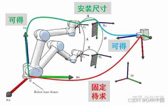
Fig 1. robot eye-to-hand calibration .
We should form a habit , That is, when we encounter problems, we first consider our required quantity and known quantity . Such as Fig 1 Shown . stay eye-to-hand In the question of , The quantity to be solved is the fixed transformation matrix from the camera to the robot base coordinate system baseTcamera . Pay attention to the... We use here base instead of robot To represent the robot base coordinate system , Because it needs to be distinguished from the coordinate system of other parts of the robot . The robot base coordinate system is fixed , And the other joints , For example, robot terminal coordinate system end, It's changing . Considering that the camera is fixed in one position , The coordinate system is fixed relative to the camera base , So our demand baseTcamera It's a fixed parameter , Calibration makes sense .
According to our festival 1 What is discussed in , Next we need to measure several sets of fixed points P Coordinates in the robot base coordinate system baseP and Coordinates in the camera coordinate system cameraP. So how to measure the coordinates of these points ? Next we need to use a calibration artifact : Chessboard .
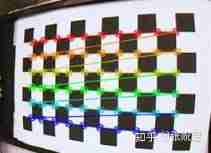
Fig 2. Checkerboard and corner recognition .
Such as Fig 2 Shown , We can accurately identify the corners of the chessboard through the corresponding visual algorithm , The specific algorithm is opencv,python,matlab, and ros And other commonly used platforms have packaged functions , Just call it directly , I will not elaborate here .
By recognizing the checkerboard , Then we can get the coordinates of the corner of the chessboard in the camera coordinate system imgP, But this is a two-dimensional coordinate , Through depth information of the object in camera, we can calculate cameraP , This will be divided into 3D Camera and 2D Camera for discussion . We can assume that we have measured cameraP , Next, we just need to measure the coordinates of the corresponding checkerboard grid points in the robot baseP, The conversion matrix between the robot and the camera can be calibrated baseTcamera. When the chessboard is calibrated , Will be fixed at the end of the robot , And the end coordinate system of the robot (end) To the base coordinate system (base) It can be calculated by the forward kinematics of the robot . Then we can measure the coordinates of the checkerboard grid points in the robot base coordinate system through the following relationship baseP :
[4]baseP = baseTendendTboardboradP
type [4] in ,baseTend and endTboard Respectively represent the robot end coordinate system (end) To the base coordinate system (base) Transformation matrix and checkerboard coordinate system (board) To the robot end coordinate system (end) The transformation matrix of . among baseTend It can be obtained in real time according to the forward kinematics of the robot , and endTboard It can be obtained by designing a checkerboard of fixed size . When the checkerboard size and installation are fixed , We can set the upper left corner of the chessboard as the origin , Then measure or obtain the translation coordinates from the checkerboard origin to the robot end coordinate origin according to the design size . In addition, the chessboard plane is generally parallel to the end plane of the robot , So we know the normal vector of the origin , Then you can calculate endTboard. boradP Represents the coordinates of the corners of the chessboard in the chessboard coordinate system , This is also obtained according to the size of the designed chessboard . In addition, we need to pay attention to the order of the corners of the chessboard in the robot coordinate system and the image coordinate system , But the general square chessboard will have the problem of rotational symmetry , That is, we can't tell whether the origin of the chessboard is the upper left corner or the lower right corner , Therefore, we can also use the following asymmetric chessboard when marking hands and eyes .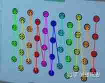
Fig 3. Asymmetric checkerboard and corner recognition , rotate 180 Degree can distinguish the upper left corner from the lower right corner .
When we follow the formula [4] The coordinates of the checkerboard corner in the robot base coordinate system are calculated baseP , Then the coordinates of the chessboard in the camera coordinate system are obtained according to the image recognition and the depth information of the camera cameraP , Then we can according to the festival 1 The method calculates the conversion matrix from the camera to the robot :
[5] baseTcamera = baseP(cameraP)-1
Next, I will discuss how to coordinate the checkerboard in the image imgP , Convert to the coordinates of the checkerboard in the camera coordinate system cameraP.
2.1. 3D The camera
The image coordinates of the camera are two-dimensional coordinates , Represents the number of rows and columns in the image . Convert the two-dimensional image coordinates into three-dimensional coordinates in the camera coordinate system , It is based on the internal parameter formula and depth value of the camera :
type [6] in z Is the depth value of the target point ,3D The camera can measure the depth of the target point , Thus, the of the target point can be calculated 3 Dimensional coordinates . Number of columns u And the number of lines v Is the coordinates of the target point in the image .x,y,z Represents the three-dimensional coordinates of the target point in the camera coordinate system . fx and fy For focus , Used to describe the proportional relationship between pixel units and three-dimensional coordinate units . u0 and v0 Is the projection position of the camera optical center in the image , It is used to calculate the displacement between the image origin and the origin of the camera coordinate system .
By finding the inverse matrix , The three-dimensional coordinates of the target point can be calculated according to the image coordinates of the target point cameraP. Camera internal parameters are generally given by the camera provider , Some camera providers will also directly provide calculated 3D point cloud information . If the camera provider gives only one depth map , No internal reference to the camera , We need to pass the Zhang Zhengyou calibration method , Calibrate the internal parameters of the camera .opencv,python,matlab And so on , You can use it directly .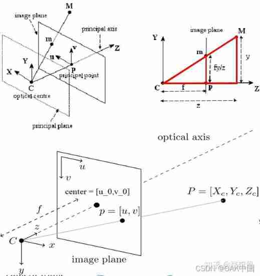
Fig 4. Camera internal reference interpretation .
2.2. 2D The camera
2.2.1. Based on plane depth z Proceed to target 3D Coordinate estimation
In section 2.1 In, we explained 3D Camera case by 2D Convert image coordinates to 3D Method of camera coordinate system . If we use 2D The camera , Then we are missing depth information , That's the formula [6] Medium z , therefore 2D Cameras are generally used for object recognition of a plane . So we only need to estimate a plane z coordinate , Then we can use the formula [6] Calculate the three-dimensional coordinates of the target point in the camera coordinate system cameraP.
2.2.2. Target selection based on plane reference point set 3D Coordinate estimation
In addition, when 2D The camera is only used to recognize the displacement and rotation of objects on the plane , We can also directly estimate the position and rotation of the target point through the following method .
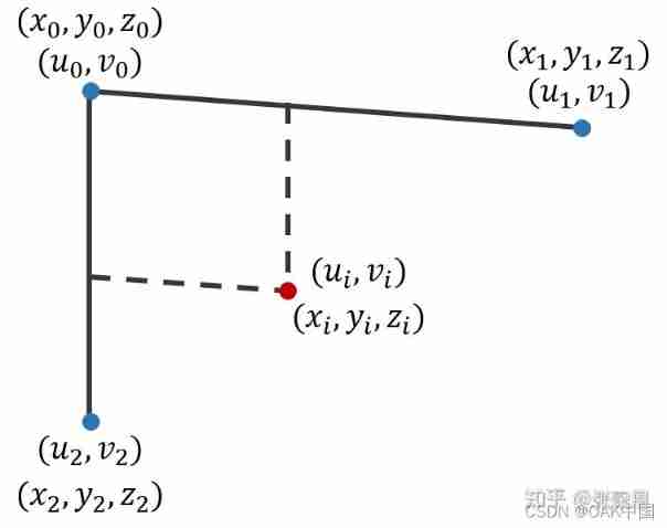
Fig 5. Representation of target point in non vertical coordinate system .
Such as Fig 5 Shown , We can place three landmarks in the corner of the camera's field of view , In this way, three location points are identified Coordinates in the image coordinate system ![[u0,v0]T](/img/d7/af5f3deb688a1faa7d5167d06beab5.jpg)
,[u1,v1]T, [u2,v2]T . Then we can construct parallelogram , Use the vectors of two coordinate axes to calculate the coordinates of the target point in the image coordinate system [ui,vi]T. Note that the coordinate axis here does not need to be a rectangular coordinate axis , So as to be more in line with the actual situation , Because it is impossible to make the two coordinate axes completely perpendicular when actually pasting markers .
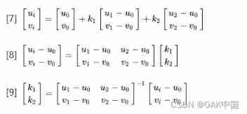
Next , We install probes at the end of the robot , By touching the sign , The coordinates of the three position points in the robot base coordinate system are obtained [x0,y0,z0]T, [x1,y1,z1]T , [x2,y2,z2]T , These three points should be on a plane . Because of the style [9] What is calculated is a proportional relationship , So according to the principle of similar triangles , We can calculate the target point in the robot base coordinate system base Coordinates of basepi= [xi,yi,zi]T :
Through [7]-[10] We can find out , By establishing a non rectangular coordinate system of three reference points in a plane , Then the image coordinates of the target point can be [ui,vi]T Convert to three-dimensional coordinates in the robot base coordinate system basepi= [xi,yi,zi]T . This method requires the target plane to be parallel to the camera plane , However, you do not need to know the depth value of the target point , There is no need for the reference point to be a rectangular coordinate system .
3. The camera is fixed at the end of the robot (eye-in-hand)
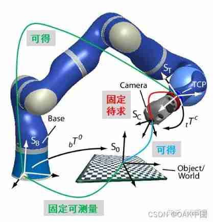
Fig 6. robot eye-in-hand calibration .
3.1. 3D The camera
Such as Fig 6 Shown , When the camera is fixed at the end of the manipulator , At this time, the transformation relationship between the camera coordinate system and the manipulator end coordinate system is fixed , The transformation relationship with the base coordinate system will change from time to time , Therefore, at this time, our quantity to be solved becomes the camera coordinate system camera To the end coordinate system of the manipulator end The transformation matrix of endTcamera . According to the Fig 6 The relationship of each coordinate system in the figure , We can list the following coordinate transformation equations :
[11] baseP= baseTendendP=baseTendendTcameracameraP
type [11] in baseP The position of the robot's chessboard is fixed to the coordinate system of a certain chessboard . There are two ways to calculate this coordinate :(i) Install a probe at the end of the manipulator , Touch the checkerboard directly from the end , The transformation matrix from the end to the base coordinate system is obtained according to the forward kinematics of the robot [ The formula ] Add the coordinates from the corner of the chessboard to the end coordinate system baseTend , We can get the coordinates of the fixed checkerboard corner in the robot base coordinate system endP.(ii) Next, we put... On the end camera, because 3D The camera can directly measure the corners of the chessboard and the corresponding 3D coordinate baseP , So we add the transformation matrix from the end of the robot to the base coordinate system baseTend And the transformation matrix from camera coordinate system to robot end coordinate system endTcamera The coordinates of the chessboard grid in the robot base coordinate system can be obtained baseP . But unfortunately , Transformation matrix from camera coordinate system to robot end coordinate system endTcamera It's our demand , We don't know yet , So we need the opposite [11] Make a simple transformation :
[12] (baseTend)-1basep(cameraP)-1=endTcamera
Observation type [12] We can find out , The three variables in the left formula are known quantities , Therefore, we can recognize the corners of the chessboard by touching the chessboard with a robot and a camera 3D Coordinate method , Find out the conversion matrix from the camera to the robot end coordinate system endTcamera .
3.2. 2D The camera
Just like Festival 2.2 As discussed in ,2D The camera cannot measure the depth value , Therefore, it is impossible to reconstruct the of the target object directly 3D Coordinate information . If 2D The camera is mounted on the arm , Most of them are used for visual servo control , There is no need to calibrate the end coordinate system of camera and robot . But we were at the festival 2.2.2 A method based on plane reference point set is proposed , The same applies here . As long as the reference point set of the working platform where the target object is located can be measured in real time , At the same time, we calibrated the coordinates of the reference point set in the robot base coordinate system in advance , Then we can use the same proportional relationship ( See formula [7]-[10]), The coordinates of the target point in the robot base coordinate system are calculated .
4. Evaluation of calibration results
After hand eye calibration , We also hope to evaluate our calibration results . According to the type [1] We can find out , The target point P The coordinates in the robot coordinate system can be obtained in two ways , One is to get the measured value directly by touching the end of the robot robotPmeasure , The other is to get the predicted value through the camera recognition and calibrated conversion matrix robotPpredict =robotTcameracameraP. By measuring several groups of target points at different positions , We can compare measurements robotPmeasure And the forecast robotPpredict =robotTcameracameraP Distance error . By calculating the mean and standard deviation of the error of each point , Finally, we can calculate the systematic error of the calibration results ( mean value ) And random error ( Standard deviation ).
5. summary
This paper discusses in 3D/2D eye-to-hand/eye-in-hand In different situations , Different calibration methods of robot hand eye relationship . As we did in the festival 1 As mentioned in , The most direct way to calibrate two coordinate systems is to measure the coordinates of the same group of points in different coordinate systems , Thus, the coordinate transformation matrix can be calculated directly by the method of matrix pseudo inverse . Of course , There are more advanced methods to calibrate the matrix when the above conditions are not met , That's classic Ax=xB The solution of the problem , among A,B It is known that ,x For the quantity to be sought . I will write an article to discuss this solution later . In addition, there is the classic Zhang Zhengyou camera calibration method , I will also take time to interpret .
OAK China | track AI New developments in technology and products
official account | OAK Visual artificial intelligence development
spot 「 here 」 Add wechat friends ( Remarks )
stamp 「+ Focus on 」 Get the latest information
边栏推荐
- This "advanced" technology design 15 years ago makes CPU shine in AI reasoning
- Network Security Learning - Information Collection
- 英特尔与信步科技共同打造机器视觉开发套件,协力推动工业智能化转型
- 一图看懂!为什么学校教了你Coding但还是不会的原因...
- 软件测试之网站测试如何进行?测试小攻略走起!
- 广告归因:买量如何做价值衡量?
- sscanf,sscanf_s及其相关使用方法「建议收藏」
- 案例大赏:英特尔携众多合作伙伴推动多领域AI产业创新发展
- Zero knowledge private application platform aleo (1) what is aleo
- 高薪程序员&面试题精讲系列120之Redis集群原理你熟悉吗?如何保证Redis的高可用(上)?
猜你喜欢

Win11控制面板快捷键 Win11打开控制面板的多种方法
What if the win11 screenshot key cannot be used? Solution to the failure of win11 screenshot key

1.19.11. SQL client, start SQL client, execute SQL query, environment configuration file, restart policy, user-defined functions, constructor parameters
The easycvr platform is connected to the RTMP protocol, and the interface call prompts how to solve the error of obtaining video recording?
Five years of automated testing, and finally into the ByteDance, the annual salary of 30W is not out of reach
Continuous learning of Robotics (Automation) - 2022-

【实践出真理】import和require的引入方式真的和网上说的一样吗
【线段树实战】最近的请求次数 + 区域和检索 - 数组可修改+我的日程安排表Ⅰ/Ⅲ

Network Security Learning - Information Collection

NFT meta universe chain diversified ecosystem development case
随机推荐
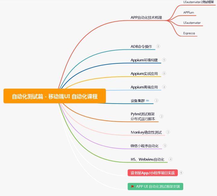
5年自动化测试,终于进字节跳动了,年薪30w其实也并非触不可及
别样肉客联手德克士在全国部分门店推出别样汉堡
B站大佬用我的世界搞出卷积神经网络,LeCun转发!爆肝6个月,播放破百万
Zhou Yajin, a top safety scholar of Zhejiang University, is a curiosity driven activist
SQL where multiple field filtering
Break the memory wall with CPU scheme? Learn from PayPal to expand the capacity of aoteng, and the volume of missed fraud transactions can be reduced to 1/30
Mathematical analysis_ Notes_ Chapter 10: integral with parameters
Why does WordPress open so slowly?
Both primary and secondary equipment numbers are 0
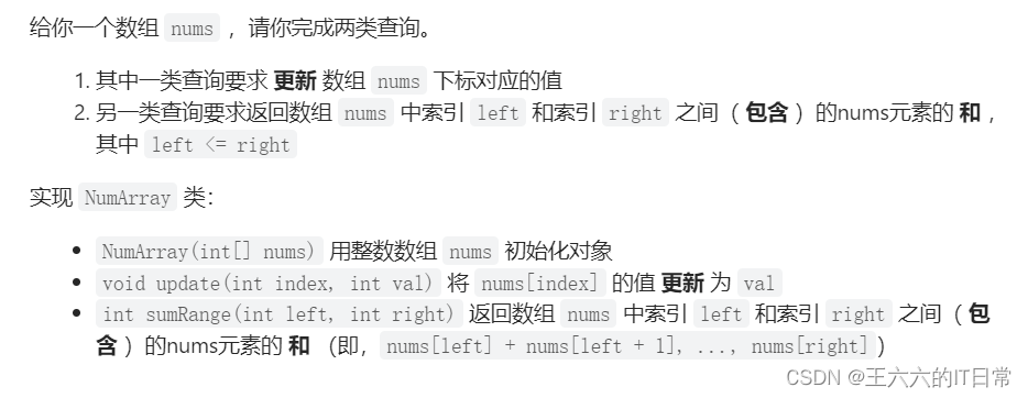
【线段树实战】最近的请求次数 + 区域和检索 - 数组可修改+我的日程安排表Ⅰ/Ⅲ
Network Security Learning - Information Collection
Nanopineo use development process record
两个div在同一行,两个div不换行「建议收藏」
Analysis on the thinking of college mathematical modeling competition and curriculum education of the 2022a question of the China Youth Cup
NFT meta universe chain diversified ecosystem development case
NanopiNEO使用开发过程记录
What if win11 pictures cannot be opened? Repair method of win11 unable to open pictures
jvm是什么?jvm调优有哪些目的?
高薪程序员&面试题精讲系列120之Redis集群原理你熟悉吗?如何保证Redis的高可用(上)?
How to conduct website testing of software testing? Test strategy let's go!