当前位置:网站首页>Systick tick timer
Systick tick timer
2022-07-07 09:06:00 【A big cat 1201】
author : A big cat 1201
special column :《STM32 Study 》
Maxim : You just try to , Leave the rest to time !

List of articles
describe
Systick Timer , It's a simple timer , about CM3,CM4 Kernel chip , There are Systick Timer .Systick Timers are often used to delay , Or the heartbeat clock of the real-time system . This can save MCU resources , Don't waste a timer .
Systic Timers are also called tick timers , It's a 24 Bit countdown timer , Count 0 when , Will be taken from RELOAD The initial value of the automatic reload timing in the register . As long as you don't put it in SysTick Enable bits in the control and status registers are cleared , Never stop , Works even in sleep mode .
Related register introduction
register CTRL
be called SysTick Control and status register , It has four bits for control and monitoring , The distribution is as follows 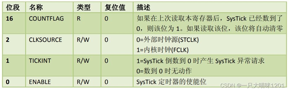
position 0:( Can make )ENABLE position . Like all peripherals , Before use , Both need to be enabled 1, That is to say, open Systic Timer , Write 0 Then close .
position 1:TICKINT position . It is a bit related to interrupts ,SysTick The timer is tied to NVIC in , Used to produce SYSTICK abnormal ( Exception number :15).Systick The priority of interrupts can also be set . Put this position 1 after ,VAL The value in the register is reduced to 0 Will enter interrupt . If write 0,VAL The value in the register is reduced to 0 Will not enter interrupt , Will restart the next round of counting .
position 2:CLKSOURE position . It is used to select the clock source .Systick The timer has two clock sources , One is the internal clock source , Its frequency is higher , In general, and HCLK identical , The other is the external clock source , Its frequency is low , yes HCLK One eighth of .
position 16:COUNTFALG position . This is a status bit , It is 0, When VAL The value in the register is reduced to 0 when , This bit will be automatically set by the hardware 1, And this bit can only read , Can't write .
register LOAD
be called SysTick Reload the load value register , It's a 24 Bit register , The distribution is shown in the figure below 
this 24 Position is from 0 To 23 Of , be called RELOAD position . The value in it is the initial value for timing ,VAL The value in the register is taken from here , When VAL The value in the register is reduced to 0 after , Will automatically from LOAD Take out the initial value from the register and put it into VAL In the register , Then continue to subtract one , Keep cycling , Unless it will enable bit writing 0.
register VAL
be called Sysytic Current value register . It's a 24 Bit register , The distribution is shown in the figure below 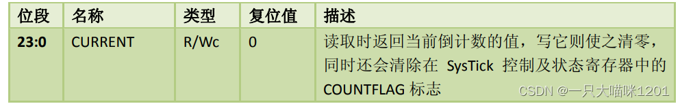
this 24 Bit is also from 0 To 23 Of , be called CURRENT position . The value in it is the initial value for timing minus one , When the value here decreases 1 To 0 after , Will automatically from LOAD Get another initial value from the register , Continue to reduce 1 operation , So circular , Unless it will enable bit writing 0. and VAL The value in the register can be modified , If you want to modify the timing time during the timing process , Then put the initial value to be timed into LOAD In the register , Right again VAL Register write 1, be VAL The register will clear 0, And then from LOAD Take the initial value in the register for new timing .
register CALIB
be called SysTick Calibration value register . Its distribution is shown in the figure below 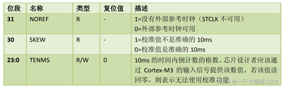
This register is rarely used , When it comes to use, Ben meow will make a detailed introduction .
And Systick Related library functions
alike ,STM The official response to Systick The use of also provides library functions , Make it more convenient for us to use , There is no need to configure the relevant registers one by one .
Clock source selection library function
stay STM In the official library function misc.c The clock source selection library function is defined in the source file .
The code is as follows :
#define SysTick_CLKSource_HCLK_Div8 ((uint32_t)0xFFFFFFFB)
#define SysTick_CLKSource_HCLK ((uint32_t)0x00000004)
#define IS_SYSTICK_CLK_SOURCE(SOURCE) (((SOURCE) == SysTick_CLKSource_HCLK) || \ ((SOURCE) == SysTick_CLKSource_HCLK_Div8))

void SysTick_CLKSourceConfig(uint32_t SysTick_CLKSource)
{

  /* Check the parameters */
  assert_param(IS_SYSTICK_CLK_SOURCE(SysTick_CLKSource));
  if (SysTick_CLKSource == SysTick_CLKSource_HCLK)
  {

    SysTick->CTRL |= SysTick_CLKSource_HCLK;
  }
  else
  {

    SysTick->CTRL &= SysTick_CLKSource_HCLK_Div8;
  }
}
Through macro definition and legitimacy judgment , We can see , The formal parameters of this function can only be SysTick_CLKSource_HCLK_Div8 The external clock , or SysTick_CLKSource_HCLK
Internal clock .
When the parameter is an internal clock , will CTRL The clock source selection bit in the register (CLKSOURE) Set as 1, This is achieved through the mapping of register address names , You can see the mapping rules in the previous corresponding article .
When the formal parameter is an external clock , will CTRL The clock source selection bit in the register (CLKSOURE) clear 0, This is achieved through the mapping of register address names , You can see the mapping rules in the previous corresponding article .
In this way , The choice of clock source is done .
Count initial value configuration function
STM The counting initial value configuration function is officially provided , We just need to calculate how many we need to count Systick The clock cycle of , as for LOAD Register and VAL The value in the register does not need to be calculated and then put in .
The code is as follows :
#define SysTick_LOAD_RELOAD_Pos 0
#define SysTick_LOAD_RELOAD_Msk (0xFFFFFFul << SysTick_LOAD_RELOAD_Pos)

#define SysTick_CTRL_CLKSOURCE_Pos 2
#define SysTick_CTRL_CLKSOURCE_Msk (1ul << SysTick_CTRL_CLKSOURCE_Pos)

#define SysTick_CTRL_TICKINT_Pos 1
#define SysTick_CTRL_TICKINT_Msk (1ul << SysTick_CTRL_TICKINT_Pos)

#define SysTick_CTRL_ENABLE_Pos 0
#define SysTick_CTRL_ENABLE_Msk (1ul << SysTick_CTRL_ENABLE_Pos)

static __INLINE uint32_t SysTick_Config(uint32_t ticks)
{

  if (ticks > SysTick_LOAD_RELOAD_Msk)  return (1);            /* Reload value impossible */

  SysTick->LOAD  = (ticks & SysTick_LOAD_RELOAD_Msk) - 1;      /* set reload register */
  NVIC_SetPriority (SysTick_IRQn, (1<<__NVIC_PRIO_BITS) - 1);  /* set Priority for Cortex-M0 System Interrupts */
  SysTick->VAL   = 0;                                          /* Load the SysTick Counter Value */
  SysTick->CTRL  = SysTick_CTRL_CLKSOURCE_Msk |
                   SysTick_CTRL_TICKINT_Msk   |
                   SysTick_CTRL_ENABLE_Msk;                    /* Enable SysTick IRQ and SysTick Timer */
  return (0);                                                  /* Function successful */
}
First, judge in this Systick Number of clock cycles , Will the initial value of the count exceed VAL register 24 The size of the bit value , If it exceeds , Just go back to 1.
If the maximum value is not exceeded , Just give it to LOAD The register of RELOAD Initial value of bit assignment timing , As for the specific content of assignment , The delay function will be explained later .
After the initial value of timing is assigned , take VAL The value in the register is cleared 0, Directly from LOAD Get the initial timing value in the register , Try to avoid timing errors .
Next is to choose the clock source , Set whether to interrupt , And enable Systick Timer .
The function of clock source selection here is the same as that of the above clock source selection function , Just use one , Of course, repeated configuration is also every problem , But it needs the same configuration .
The time delay function
It was mentioned at the beginning ,Systick Timing is often used as a delay , Its original purpose is to save resources , Save timer resources , So we should also save interrupt resources when using it for timing , The timing is carried out by means of interruption .
Benmew will explain the delay function written by punctual atoms that we use more .
The code is as follows :
void delay_init()
{

	SysTick_CLKSourceConfig(SysTick_CLKSource_HCLK_Div8);	// Select the external clock  HCLK/8
	fac_us=SystemCoreClock/8000000;				// For the system clock 1/8
	fac_ms=(u16)fac_us*1000;					// Not OS Next , For each ms Needed systick The number of clocks
}
First, the external clock is selected through the clock source selection function in the program , about STMF103ZET6 Chip , At this time Systick The clock frequency is HCLK One eighth of the clock frequency , That is to say 72MHZ/8=9MHZ.
Here, the main function of delay initialization is to calculate two factors fac_us and fac_ms.
1️⃣fac_us:
This factor is a value , Its meaning is that time is 1 Microsecond , There will be a few Systick Clock cycle .SystemCoreClock The value of is the system clock frequency , That is to say 72MHZ.
Divide 8000000 It can be seen as two steps , Divide by 8 Carry out one eighth frequency division , Get is 9MHZ frequency , Divided by 1000000 What you get is 1 Within microseconds Systick Number of clock cycles .
2️⃣fac_ms:
This factor is also a value , Its meaning is that time is 1 millisecond , There will be a few Systick Clock cycle . because us And ms The rate of advance is 1000, therefore fac_ms The value of is fac_us Based on the value of 1000.
In this way , We will Systick The timer is initialized , In fact, we have calculated two factors .
Next I'll see how to use it .
Microsecond level timer
The code is as follows :
oid delay_us(u32 nus)
{

	u32 temp;
	SysTick->LOAD=nus*fac_us; 					// Time loading
	SysTick->VAL=0x00;        					// Clear the counter
	SysTick->CTRL|=SysTick_CTRL_ENABLE_Msk ;	// Start counting down
	do
	{

		temp=SysTick->CTRL;
	}while((temp&0x01)&&!(temp&(1<<16)));		// Wait for time to arrive
	SysTick->CTRL&=~SysTick_CTRL_ENABLE_Msk;	// Turn off the counter
	SysTick->VAL =0X00;      					 // Clear the counter
}
Multiply the factor calculated during initialization by the time of delay , Get is the beat number , That is, how many times is the timing time Systick Clock cycle .
Then put this value in LOAD In register RELOAD Bit as the initial value of timing .
then VAL The value in the register is cleared 0, Let it go directly from LOAD Get the initial timing value in the register , To reduce timing error .
And then CRTL Medium ENABLE Bit enable , That is, turn on the timer
Then it enters the cycle . Keep reading CTRL Value in register , Just to watch the seats 16 That is to say COUNTFLAG The state of , If it 0, It means that the timing is not over , Then continue the cycle , If it is 1, It means that the timing is over .
Finally, turn off the counter , It will enable you to be clear 0, And will VAL The value in the register is cleared 0.
The above is the microsecond delay program , Next, let's look at the millisecond delay program
Millisecond level timer
The code is as follows :
void delay_ms(u16 nms)
{

	u32 temp;
	SysTick->LOAD=(u32)nms*fac_ms;				// Time loading (SysTick->LOAD by 24bit)
	SysTick->VAL =0x00;							// Clear the counter
	SysTick->CTRL|=SysTick_CTRL_ENABLE_Msk ;	// Start counting down
	do
	{

		temp=SysTick->CTRL;
	}while((temp&0x01)&&!(temp&(1<<16)));		// Wait for time to arrive
	SysTick->CTRL&=~SysTick_CTRL_ENABLE_Msk;	// Turn off the counter
	SysTick->VAL =0X00;       					// Clear the counter
}
You can see , Its process is the same as the microsecond delay program , Just use different factors , What we use here is fac_ms, This value has been calculated in the initialization function .
The above is the whole content of the delay function , But this delay has a time limit , You can't delay as long as you want , Next, benmeow will show you the delay range .
Delay range
Take this cat STM32F103ZET6 Chip as an example , Its system clock is 72MHZ Of .Systick The clock source of the timer is 9MHZ Of .
9000000 Divide 1000000 And what you get is 9, therefore fac_us The value is 9, That is to say 1 In microseconds 9 individual Systick The clock .
and fac_ms The value of is 9000, That is to say 1 Within milliseconds 9000 individual Systick The clock .
and VAL The register has LOAD The registers are 24 Of , Its maximum value is
111111111111111111111111, After converting to multiply by decimal is 16777215.
For microsecond level timing , The maximum timing duration is
16777215/9=1864135 Microsecond , That is to say 1864.135 millisecond .
When using the timing in milliseconds , The maximum timing duration can only be an integer of milliseconds , That is to say 1864 millisecond .
This is it. Systick The maximum timing duration that can be reached by a timer cycle . Of course, you can also achieve longer timing through circular nesting .
summary
Timing or delay is what we are using STM32 Functions often used in , and Systick Timers can solve most of our timing situations , And it's easy to use , It takes up less resources . in general ,Systick The steps of using the timer are , Choose the clock source , Calculate the initial value of the count , Put in LOAD In the timer , Then start the timer , Then monitor whether the timing is completed .
If it helps you , Please click three times to support benmew .
边栏推荐
- What is the value of getting a PMP certificate?
- Output a spiral matrix C language
- Nanjing commercial housing sales enabled electronic contracts, and Junzi sign assisted in the online signing and filing of housing transactions
- 如何统计项目代码行数
- Goldbach conjecture C language
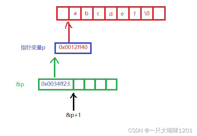
- C语言指针(上篇)
- Recommended by Alibaba P8, the test coverage tool - Jacobo is very practical
- 实现自定义内存分配器
- PMP Exam details after the release of the new exam outline
- Unityshader introduction essentials personal summary -- Basic chapter (I)
猜你喜欢

为不同类型设备构建应用的三大更新 | 2022 I/O 重点回顾
C语言指针(中篇)
Goldbach conjecture C language
Druid monitoring - Introduction to JMX usage and principle
C语言指针(特别篇)
Several stages of PMP preparation study
C语言指针(习题篇)
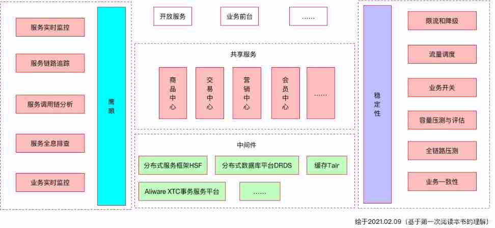
Reflections on the way of enterprise IT architecture transformation (Alibaba's China Taiwan strategic thought and architecture practice)
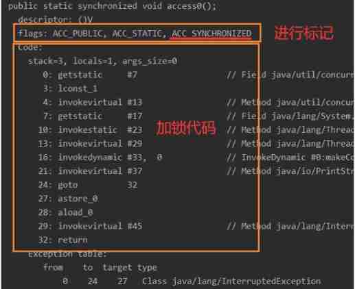
Synchronized underlying principle, volatile keyword analysis
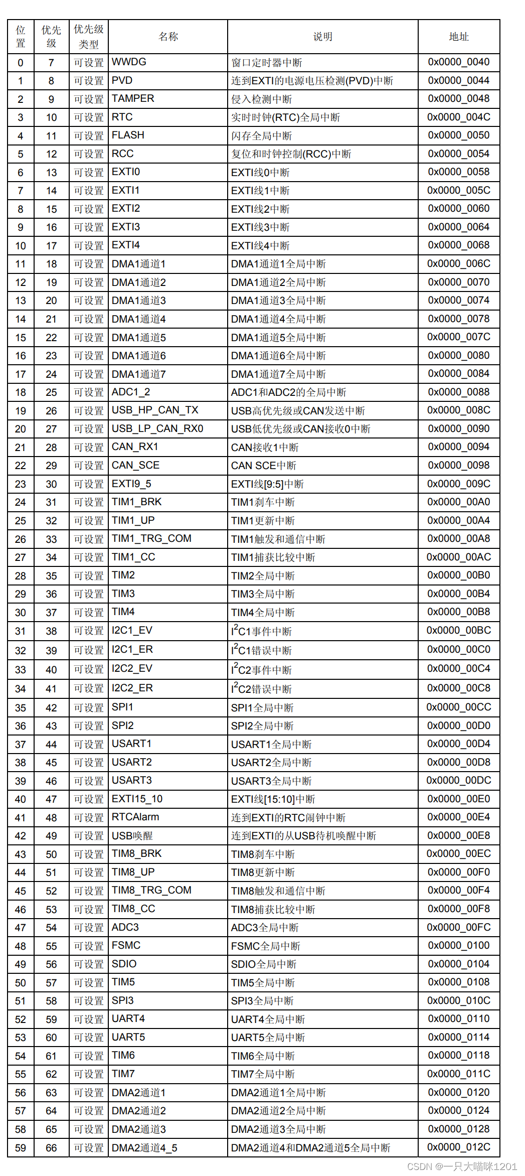
NVIC中断优先级管理
随机推荐
Uniapp wechat applet monitoring network
Problems encountered in the use of go micro
E-commerce campaign Guide
Calculation s=1+12+123+1234+12345 C language
数据在内存中的存储
模拟卷Leetcode【普通】1706. 球会落何处
PMP experience learning and sharing process
Full link voltage test of the e-commerce campaign Guide
模拟卷Leetcode【普通】1557. 可以到达所有点的最少点数目
How to realize sliding operation component in fast application
Cmake command line use
Simulation volume leetcode [general] 1705 The maximum number of apples to eat
PPT模板、素材下载网站(纯干货,建议收藏)
【ChaosBlade:根据标签删除POD、Pod 域名访问异常场景、Pod 文件系统 I/O 故障场景】
systemd
【ChaosBlade:节点 CPU 负载、节点网络延迟、节点网络丢包、节点域名访问异常】
【Istio Network CRD VirtualService、Envoyfilter】
Mountaineering team (DFS)
RuntimeError: Calculated padded input size per channel: (1 x 1). Kernel size: (5 x 5). Kernel size c
cmake命令行使用