当前位置:网站首页>[play with FPGA learning 5 in simple terms ----- reset design]
[play with FPGA learning 5 in simple terms ----- reset design]
2022-07-02 11:02:00 【Ape Zhou】
Play in depth FPGA Study 5----- Reset design
Asynchronous reset and synchronous reset
FPGA The common reset methods in the design are asynchronous reset and synchronous reset . Asynchronous , It means that the reset signal and system clock signal can be triggered at any time , They are independent of each other .
Asynchronous reset instance
Here is a code for asynchronous reset :
always @ (posedge clk or negedge rst_n)
		if(!rst_n) b <= 1'b0;
		else b <= a;
The following figure is the result of the above code synthesis RTL View , You can see FPGA All registers have an asynchronous zeroing end (CLR), In the design of asynchronous reset , This port is usually connected to a low-level effective reset signal rst_n, Even if the design is high-level reset , After the actual synthesis, the asynchronous reset signal will also be reversely connected to this CLR End .
Synchronous reset instance
Here is a code for synchronous reset :
always @ (posedge clk)
			if(!rst_n) b <= 1'b0;
			else b <=a;
After code synthesis RTL View , Compared with asynchronous reset , Synchronous reset does not use registers CLR port , The actual circuit synthesized is only the reset signal rst_n As an enable signal of input logic , that , Such synchronous reset is bound to increase FPGA Internal resource consumption .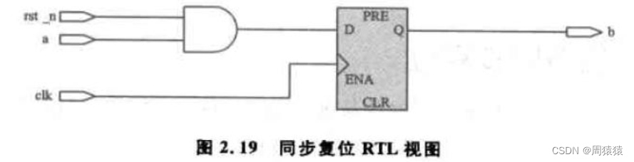
that , Which is better between asynchronous reset and synchronous reset ? It can only be said , Each has its own advantages and disadvantages .FPGA The register of has a dedicated port that supports asynchronous reset , Using asynchronous reset does not need to increase the additional resources of the device , But asynchronous reset also has hidden dangers . The metastable problem of asynchronous clock domain also exists between asynchronous reset signal and system clock signal . Synchronous reset at clock signal clk When the rising edge of is triggered, judge whether the system is reset , This reduces the probability of metastable states ( Just lower , It's impossible to avoid ); Its disadvantage is that it needs to consume more device resources , Unable to make full use of dedicated Reset the port CLR.
Then through the following example of asynchronous reset of two-level registers to illustrate the hidden dangers of asynchronous reset .
always @ (posedge clk or negedge rst_n)
			if(!rst_n) b <= 1'b0;
			else b <=a;
always @ (posedge clk or negedge rst_n)
			if (!rst_n) c <= 1'b0;
			else c <= b;
After code synthesis RTL The view is as shown :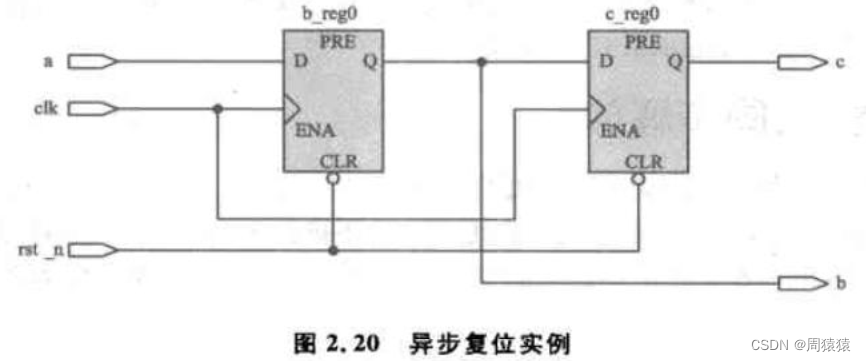
Under normal circumstances , stay clk The rising edge of will c Updated to b,b Updated to a. Once reset is entered ,b、c Will be cleared ; However, the reset signal cannot be determined rst_n When will it end . If it ends in b_reg0 and c_reg0 Of {latch edge setup time,latch edge + hold time} Out of time , Then everything will be normal . But if the opposite is true , What will happen ? Reset signal rst_n The revocation of ( Change from low level to high level ) Appear in the clk The establishment time or holding time of the latch data , here clk detected rst_n The state will be metastable ( Not sure 0 still 1). You can see from the code , If at this time b_reg0 Think rst_n by 0, Then keep reset and reset ; And if you think rst_n by 1, Then jump out of the reset , Perform the corresponding operation .
Because of this time rst_n uncertainty , There may be 4 In this case , namely b_reg0 and c_reg0 Reset all or jump out of reset , Or reset one by one and jump out of reset , Then the latter will cause the problem that the system functions are not synchronized .
Reset and metastable
Metastable state has relatively little effect on a register , But for the metastable effect of registers such as bus type, the problem is big , Maybe it's a fatal blow .
Asynchronous reset 、 Simultaneous release
Asynchronous reset will affect registers recovery Time , Cause design stability problems , Especially for the unconscious reset of the state machine , Will lead to an uncertain state . There are similar problems with synchronous reset , And for devices without a dedicated port for synchronous reset, additional logic resources will be added .
Here is a more reliable asynchronous reset 、 Double buffer circuit for synchronous release . The circuit consists of two stacked registers triggered by the same clock edge , The clock must be in the same clock domain as the target register .Verilog The code is as follows :
input clk;   // System clock signal
input rst_n;  // Input reset signal , Low efficiency
output rst_nr2;  // Asynchronous reset 、 Release output synchronously
reg rst_nr1,rst_nr2;
// Two level cascade reset is generated , Low level reset
always @ (posedge clk or negedge rst_n)
		if(!rst_n) rst_nr2 <= 1'b0;
		else rst_nr2 <= rst_nr1;
The circuit realized by this code is shown in the figure :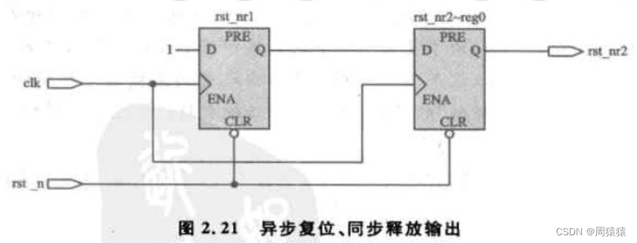
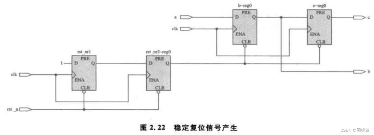
So since , It not only solves the problem of resource consumption of synchronous reset , The metastable reset problem is solved again , Its fundamental thought , It also synchronizes asynchronous signals .
PLL Reset the design after configuration
quite a lot FPGA Many clocks are involved in the design , Use the inside of the device PLL perhaps DLL It will make the management of multiple clocks easier . But when multiple clocks are used PLL/DLL When it comes into being , How can their system reset circuit be designed to be more stable ?
As shown in the figure , First use FPGA External input clock clk take FPGA Input reset signal rst_n Do asynchronous reset 、 Synchronous release processing , Then the reset signal is input PLL, meanwhile clk Also input PLL. The original intention of the design is PLL Before the output clock is valid , The rest of the system remains reset .PLL Output locked The signal is PLL The active output is always low ,PLL The signal will not be pulled up until the output is stable and effective , So here we put FPGA External input reset signal rst_n And this locked The signal phase and as the reset signal of the whole system , Yes, of course , This reset signal also needs to be properly PLL Output clock is reset asynchronously 、 Synchronous release processing . in other words , In order to achieve a reliable and stable reset signal , In this design, the reset signal is processed twice , Respectively in PLL Before and after output PLL After output .
The engineering source code of this design is as follows :
module sys_ctrl(
						clk,rst_n,sys_rst_n,clk_25m,clk_100m
						);
input clk;      //FPGA Input clock signal 25Mhz
input rst_n;   // System reset signal
output sys_rst_n;   // System reset signal , Low efficiency
output clk_25m;    //PLL Output 25MHZ clock frequency
output clk_100m;   //PLL Output 100MHZ clock frequency
wire locked;    //PLL Output valid flag bit , High means PLL The output is valid
/PLL Reset signal generation , Highly effective
// Asynchronous reset , Simultaneous release
wire pll_rst;     //PLL Reset signal , Highly effective
reg rst_r1,rst_r2;
always @ (posedge clk or negedge rst_n)
				if(!rst_n) rst_r1 <= 1'b1;
				else rst_r1 <= 1'b0;
always @ (posedge clk or negedge rst_n)
 				if(!rst_n) rst_r2 <= 1'b1;
 				else rst_r2 <= rst_r1;
 assign pll_rst = rst_r2;
 // System reset signal generation , Low efficiency
 // Asynchronous reset , Simultaneous release
 wire sys_rst_n;   // System reset signal , Low efficiency
 wire sysrst_nr0;
 reg sysrst_nr1,sysrst_nr2;
 assign sysrst_nr0 = rst_n & locked;  // System reset knows PLL Effective output
 always @ (posedge clk_100m or negedge sysrst_nr0)
 			if(!sysrst_nr0) sysrst_nr1 <= 1'b0;
 			else sysrst_nr1 <= 1'b1;
 always @ (posedge clk_100m or negedge sysrst_nr0)
 			if(!sysrst_nr0) sysrst_nr2 <= 1'b0;
 			else sysrst_nr2 <= sysrst_nr1;
 assign sys_rst_n = sysrst_nr2;
 // Exemplification PLL Generation module
 PLL_ctrl      uut_PLL _ctrl(
 									.areset(pll_rst),    //PLL Reset signal , High level reset
 									.inclk0(clk),    //PLL Input clock ,25MHz
 									.c0(clk_25m),  //PLL Output 25MHz clock frequency
 									.c1(clk_100m),   //PLL  Output 100MHZ  clock frequency
 									.locked(locked)   //PLL Output valid flag bit , High level means PLL The output is valid
 									);
 endmodule
边栏推荐
猜你喜欢

Leetcode+ 76 - 80 storm search topic
QT学习日记7——QMainWindow
集成学习概览
Special topic of binary tree -- acwing 19 The next node of the binary tree (find the successor of the node in the tree)
JSP webshell free -- webshell free
华为AppLinking中统一链接的创建和使用

Nodejs+express+mysql simple blog building
JSP webshell免殺——JSP的基礎
MongoDB 学习整理(条件操作符,$type 操作符,limit()方法,skip() 方法 和 sort() 方法)
![Luogu p5536 [xr-3] core city (greed + tree DP looking for the center of the tree)](/img/dc/2aa55c9b3f23c292820a56ea72fedd.png)
Luogu p5536 [xr-3] core city (greed + tree DP looking for the center of the tree)
随机推荐
MySQL lethal serial question 4 -- are you familiar with MySQL logs?
【快应用】Win7系统使用华为IDE无法运行和调试项目
JSP webshell free -- the basis of JSP
主键策略问题
The URL in the RTSP setup header of the axis device cannot take a parameter
[SUCTF2018]followme
LabVIEW为什么浮点数会丢失精度
最详细MySql安装教程
洛谷 P5536 【XR-3】核心城市(贪心 + 树形 dp 寻找树的中心)
In the face of uncertainty, the role of supply chain
Open the encrypted SQLite method with sqlcipher
【深入浅出玩转FPGA学习2----设计技巧(基本语法)】
Huawei game failed to initialize init with error code 907135000
Special topic of binary tree -- [deep base 16. Example 7] ordinary binary tree (simplified version) (multiset seeks the precursor and subsequent sentry Art)
2022-06-17
二叉树专题--AcWing 1497. 树的遍历(利用后、中序遍历,构建二叉树)
1287_FreeRTOS中prvTaskIsTaskSuspended()接口实现分析
MySQL lethal serial question 3 -- are you familiar with MySQL locks?
Thanos Receiver
HDU1234 开门人和关门人(水题)