当前位置:网站首页>2837xd code generation - stateflow (1)
2837xd code generation - stateflow (1)
2022-07-02 09:43:00 【Quikk】
2837xd Code generation ——StateFlow(1)
stay Command Window Type in sf Can enter the , It can also be done through Simulink In the library StateFlow Sub library entry .
StateFlow Finite state machine , Reuse matlab when , May feel : A simple if Statements or ++ The operation needs to be built too complex . But the introduction of state machine can greatly reduce this situation .
Entering the library function module, you can see that these three components are all state machine modules , Learn one by one : First look at Chart modular .

1 Chart modular
Create a new Chart modular , After opening , Right click to enter Properties Set it up .
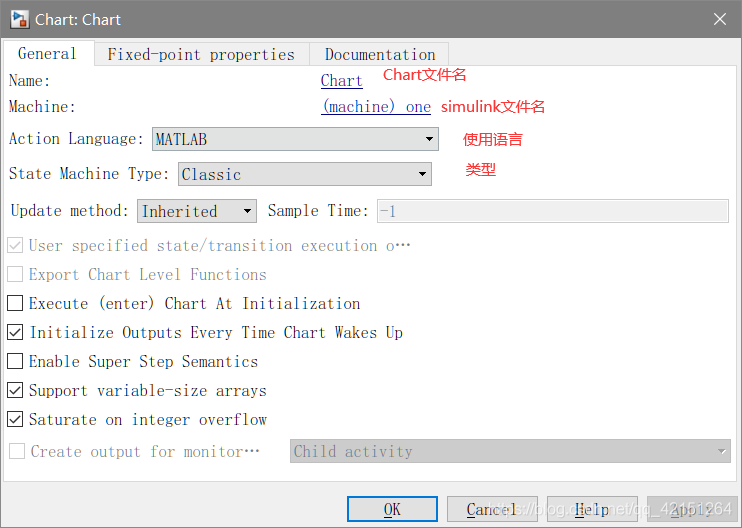
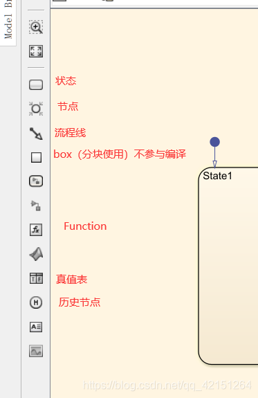
On the left side of the interface are some Chart Components used in :
among , There is only mutual exclusion between each module ( Only one can execute ) And parallelism . There will be an execution order identifier in the upper right corner under the parallel relationship .
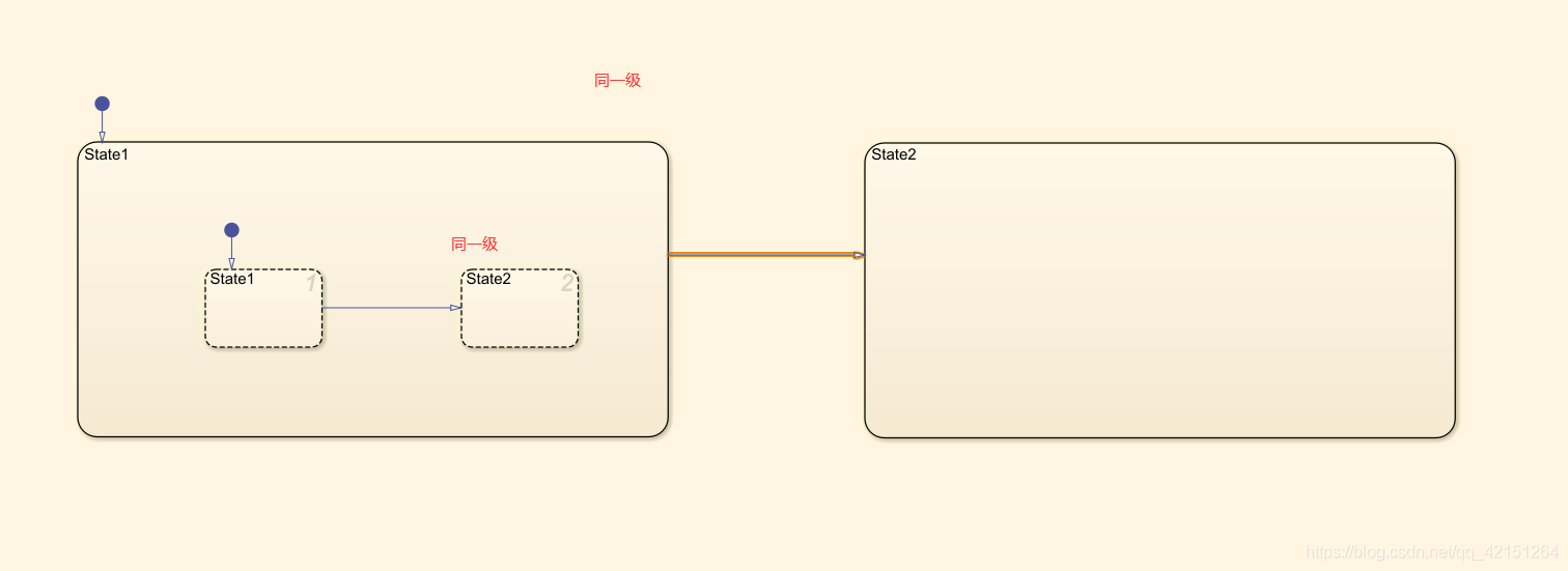
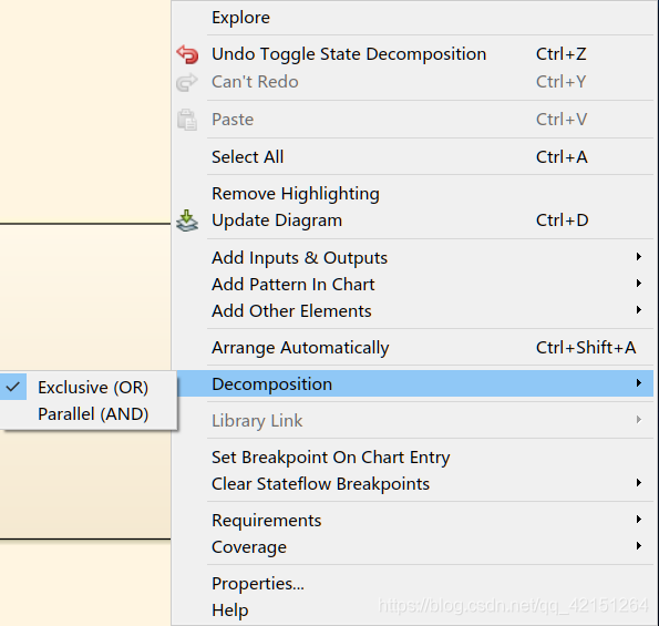
Which is divided into different levels by modules , The content under the same module is a level , If you need to set parallel and mutually exclusive relationships . Right click the blank space of the level to be set and select Decomposition Choose parallel and mutually exclusive relationships .
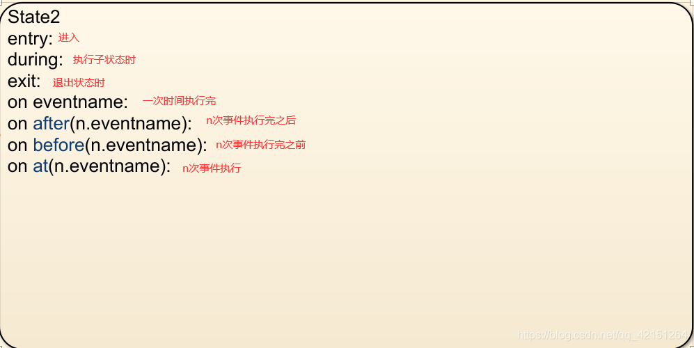
State Modules have some keywords that can be used to define the actions to be performed after entering these modules :

Using the above knowledge, we can build a simple model , Take a look at the concept of flow chart .

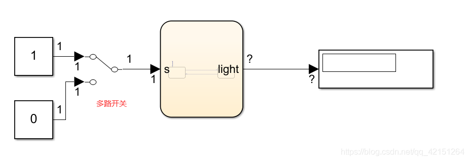
First, build a simple model as shown in the above figure ,s Is the condition ,light It's the result of action . This is a process that simulates the switching of lights , turn on the light (s=1) Obviously, we need to give ,light The program needs to run to produce relevant results . Now enter Model Explorer The relevant settings are made in .


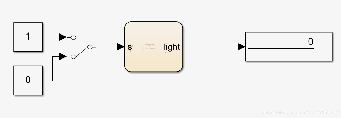
And then in Simulink Add relevant external modules , Give and display input and output .
The simulation results are as follows . change s Value , Can be changed accordingly light Value .
Transform the above process , Join the event .Open_switch(Close_Switch),b And in Model Exporer Defined in . Here, pay attention to the defined input port and demux The input should be consistent .

Then build a circuit ,Input3 It is used to activate the module . You can know at this time , It's not just about s=1, And need the rising edge (Open_switch The rising edge of the trigger of the event setting ) To trigger light=1. Similar to the rising edge in digital electricity, the corresponding signal can be locked .

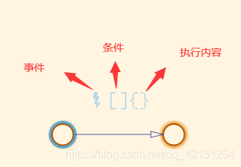
In order to better write the process ,StateFlow The concept of connection node is introduced . Click on Parretn The following structures can be set .
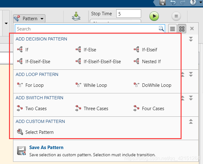
You can also add conditions for your connection , When the mouse is placed on the line between the two connection points, the following marks will automatically appear , By default, when one node has multiple branches , Will give priority to the conditional branch .:
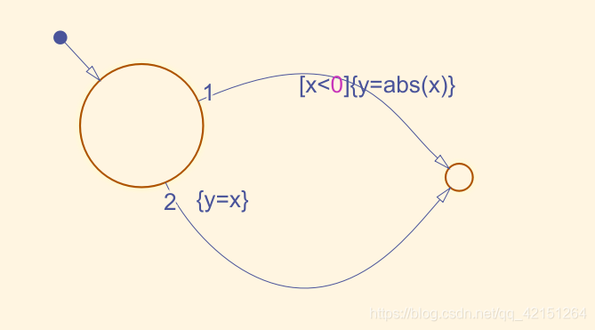
Pictured , Set up the following branches , Equate to C Code :
if (x<0)
    y=abs(x);
else
    y=x;
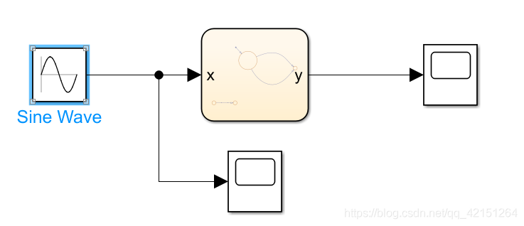
stay Model Explorer Set relevant... In data Properties of , Given inputs and outputs . The given input here is 1Hz The sine wave of .

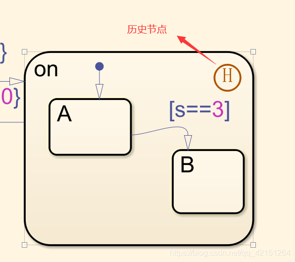
Now combine the state of the first switch lamp , If there are two states in the light on state (A、B) Represents different brightness . Then if we set the brightness for the first time , I certainly don't want to adjust the brightness again next time I turn on the light . Therefore, historical nodes are introduced here , That is, you can remember the last exit state , Even though A It's the default state . But the state at this time is determined by the state of the last exit :
2 Model instance construction
2.1 Car status judgment
Build the following logic circuit for judging the car state , Be able to define the events generated above , Run , It can simulate gear shifting and start stop status monitoring :

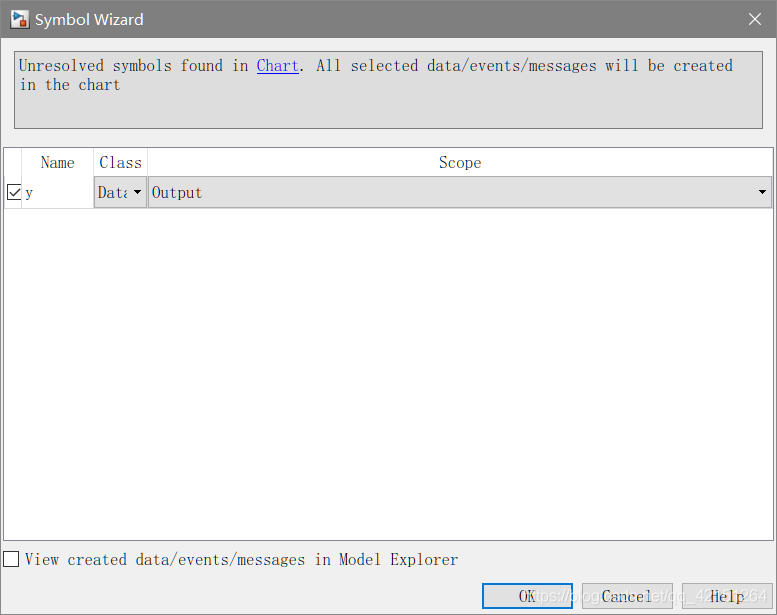
After the completion of construction , You can click run directly , At this time, because there is no definition of related data and event An automatically defined interface will pop up , Make relevant modifications above to quickly add :
Build peripheral circuits , Set the device runtime triggered by related events , Change the simulation duration to inf( Infinite length ), You can operate and observe experimental phenomena :

2.2 Media playback status detection
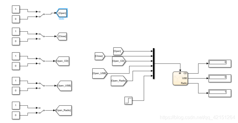
The media playing status can be observed through the flow chart , This example introduces historical nodes and state detection , Build as shown in the following figure chart, You can see in the power_on Some of the state transition flow charts in have no trigger conditions ( That means anything can trigger ). for example , If now in USB state , If sent Open_CD(Open_Radio) After that, state transition can be triggered .

Right click on the status to enter the attribute (Properties), Modify the status output , Then you can observe the status at the output port ( Boolean variable output , by 1 It means in secondary state ).

The history node is added , Represents the next entry power_on When the module , It will directly enter the state of the last exit .
Build the external circuit as shown in the figure below :
2.3 2837xd Running water lamp online debugging
First, build the following chart, here led1 and led2 It's all output . Direct connection GPIO Interface .

The picture below is led1 and led2 Output waveform of , Identified in the figure 1.2.3.4 Corresponding to the execution process in the above figure . That's the cycle 3 After that , Out of the loop , Then go out and wait , Enter the next cycle . Here the test found , It will last one step in the state , Act at the node (3、4) It will take another step .[ The step size is set to 0.5s], Setting of relevant parameters , Please refer to the previous blog article .

Program peripheral circuit diagram :

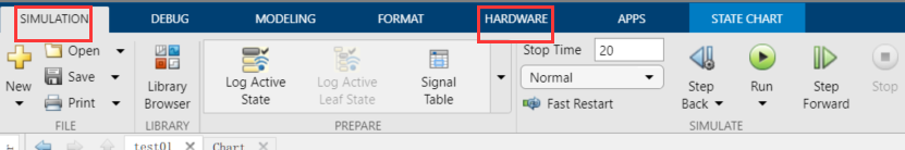
This is a debugging skill , The following figure SIMULATION and HARDWARE There is one in each RUN,SIMULINK Medium RUN Hardware can be disconnected , Run the software running results directly , That is, it can also be easily debugged chart Output module .HARDWARE Medium RUN Is to generate DSP Code burning into DSP And then run .
边栏推荐
- C语言之到底是不是太胖了
- How to use PHP spoole to implement millisecond scheduled tasks
- MySQL multi column in operation
- College Students' CET-4 and CET-6 composition template (self created version, successfully crossed CET-6)
- Alibaba / popular JSON parsing open source project fastjson2
- Pool de connexion redis personnalisé
- Personal experience & blog status
- 因上努力,果上随缘
- PI control of three-phase grid connected inverter - off grid mode
- 在SQL注入中,为什么union联合查询,id必须等于0
猜你喜欢

DTM distributed transaction manager PHP collaboration client V0.1 beta release!!!

上班第一天的报错(AWVS卸载不彻底)

逆变器simulink模型——处理器在环测试(PIL)

三相逆变器离网控制——PR控制

自定義Redis連接池

JDBC回顾

三相并网逆变器PI控制——离网模式

Memories of a chat

Navicat remote connection MySQL reports an error 1045 - access denied for user 'root' @ '222.173.220.236' (using password: yes)

Creation and jump of activity
随机推荐
JVM instruction mnemonic
2837xd 代碼生成——StateFlow(4)
每天睡觉前30分钟阅读_day3_Files
JDBC review
Matplotlib swordsman - a stylist who can draw without tools and code
C语言之最小数
How to use PHP spoole to implement millisecond scheduled tasks
Discussion on improving development quality and reducing test bug rate
Pool de connexion redis personnalisé
Read Day5 30 minutes before going to bed every day_ All key values in the map, how to obtain all value values
tinyxml2 读取和修改文件
Number structure (C language) -- Chapter 4, compressed storage of matrices (Part 2)
C语言之判断直角三角形
Safety production early warning system software - Download safety production app software
记录一下初次使用Xray的有趣过程
In depth analysis of how the JVM executes Hello World
QT qlabel style settings
Say goodbye to 996. What are the necessary plug-ins in idea?
互联网API接口幂等设计
记录下对游戏主机配置的个人理解与心得