当前位置:网站首页>Feedforward feedback control system design (process control course design matlab/simulink)
Feedforward feedback control system design (process control course design matlab/simulink)
2022-06-27 10:15:00 【Chloroplasts do not forget to breathe】
WeChat official account : Chuangxiang diary
Send keywords : Feedforward and feedback
Get the full report for free +matlab/simulink Simulation source file
One 、 Course design task analysis
The transfer function of a given process is G_PC (s)=(s+1)/(s+2)(2s+3) ,G_PD (s)=5/(s+2) , Controller use PID law . Try to design a feedforward - Mathematical model of feedforward regulator in feedback control system G_ff, And use SIMULINK and MATLAB Program simulation implementation . When the disturbance signal F(s) Unit step signal and SINS The signal , System setpoint R(s) by 1 when , adjustment PID Parameters , It can overcome interference F Impact on the system , It can also track the set value R The change of .( Suppose the transfer function of the detection transmission link is 1).
1、 The design requirements
① The model expression of feedforward controller is given ;
② Provide system simulation diagram ;
③ Give the debugging steps of the system after the design is completed , Explanation of experimental results and analysis of experimental data ;
④ If the control channel has large pure delay , namely G_PC (s)=(s+1)/(s+2)(2s+3) e^(-10s), Control how performance changes ? The improved feedforward - Structure model control scheme and simulation results of feedback hole control system .
⑤ Write the experiment report .
2、 Process analysis
In the system, there is a feedforward control to compensate the main disturbance signal , There is also the problem of using feedback control to overcome other interference signals , Such a system is feedforward - Feedback control system . The function of the feedforward control system is to compensate the main interference signals , It can be aimed at the main interference signal , Set the corresponding feedforward controller . The purpose of introducing feedback control is that the system can overcome the influence of all interference signals on the regulated quantity , In addition to known interference signals , There are other interference signals in the system , These disturbance signals have little influence on the system , Some can be considered , Some cannot be considered or measured , Through feedback control to overcome . The signals to be measured in the system include both modulated and disturbed signals .
Two 、 Object property analysis
From the title we can see , The transfer function of the control channel of the system is G_PC (s)=(1/6(s+1))/(1/2 s+1)(2/3 s+1) , The transfer function of the disturbance channel is G_PD (s)=5/(s+2). Therefore, the controlled process is a self balancing multi capacity process , That is, when the input changes , No additional control is required , The process can spontaneously approach a new equilibrium state .
Static gain of the controlled process ( Amplification factor )K=1/6, That is, the ratio of output variation to input variation , It is easy to know that the amplification factor is small , The control function of the process is weak . According to its time constant T_1=1/2,T_2=2/3, The control process is slow .
Interfere with channel transmission G_PD (s)=5/(s+2), Its static gain K=5/2, It can be seen that the amplification coefficient of the disturbance channel is large , That is, a small disturbance will have a greater impact on the system , Feedforward shall be used - Feedback control to eliminate the influence of disturbance .
3、 ... and 、 Control scheme design and simulation
1、 Initial structure of the system
According to the design requirements , The transfer function of the control channel is G_pc(s)=(s+1)/((s+2)(s+3)) And the transfer function of the interference channel is G_pd(s)=5/(s+2), Input set to unit step signal , Do you want to join us PID Controller and feedforward controller , Form a simple single closed-loop system , The original structure block diagram of the system is established as shown in Figure 4-1 Shown .
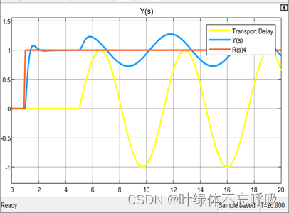
When the interference input is set to the unit step response signal , The simulation time is set to 20s, In the 10s Add interference when , The system simulation waveform is shown in the figure 4-2 Shown .
From the figure 4-2 You know , When there is no controller , Output cannot follow a given , There is a serious margin , After the interference is added , The anti-interference performance of the system is very poor .
When the interference input is set to a sinusoidal signal , The simulation time is set to 10s, The system simulation waveform is shown in the figure 4-3 Shown .
From the figure 4-3 You know , The system has poor rapidity , And it can not produce stable oscillation after the introduction of sinusoidal signal .
2、 Join in PID Behind the controller
Add... To the system PID The controller keeps the control variable at the set value . Get the system simulation structure diagram 4-4 Shown .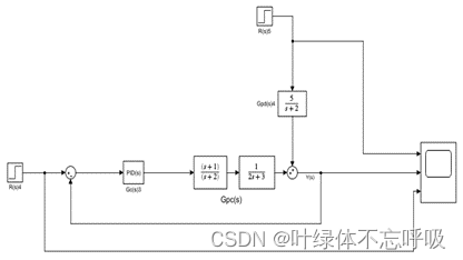
When the interference input is set to the unit step response signal , The simulation time is set to 10s, In the 5s Add interference when , The system simulation waveform is shown in the figure 4-5 Shown .

From the figure 4-5 You know , The system can be fast and stable , However, the stability of the system decreases obviously after the disturbance occurs , There is a large overshoot , And it will take longer to regain stability again .
When the interference input is set to a sinusoidal signal , The simulation time is set to 20s, In the 5s Add interference when , The system simulation waveform is shown in the figure 4-6 Shown .
From the figure 4-6 You know , When the disturbance occurs, the system is affected to produce overshoot and the feedback control function has a certain lag , Disturbance cannot be eliminated in time .
3、 After adding the feedforward controller
A feedforward controller is introduced to measure the disturbance in the process and change the control quantity according to the measured value . Not joined at this time PID controller , Only the feedforward control system is composed as shown in the figure 4-7 Shown .
When the interference input is set to the unit step response signal , The simulation time is set to 20s, In the 5s Add interference when , The system simulation waveform is shown in the figure 4-8 Shown .

From the figure 4-8 You know , The system is little affected by interference when interference occurs , But the system has a large margin , Can't follow the given well .
When the interference input is set to a sinusoidal signal , The simulation time is set to 20s, In the 5s Add interference when , The system simulation waveform is shown in the figure 4-9 Shown .

From the figure 4-9 You know , The system can still ensure the stability of the system in case of sinusoidal signal interference , Make the system suffer little interference , But the system has a large margin , Can't follow the given well .
4、 feedforward - Feedback control system
( See report for details )
5、 The system has a large lag
( See report for details )
6、 Smith predictor compensator
( See report for details )
Four 、 Design summary and experience
Through this course design , The three members of our group are responsible for feedforward and feedback control 、PID Parameter setting 、 We have a deeper understanding of the hazards of lagging links and Smith control , Realized the importance of division of labor and cooperation in the group , And apply what we have learned in the textbook to practice . In the process , We also have a lot of problems , I can't adjust to the ideal one many times PID Controller parameters , By searching for information , got it Simulink Can be done PID Self tuning . Understand this , We have abandoned the traditional method of setting parameters , Use Simulink Library Browser Medium Continuous In the module PID controller Self contained Tuner Function to complete PID Automatic parameter setting . Let's talk about MATLAB Have a deeper understanding of the use .
Even though PID The problem of parameter setting has been solved , But at the beginning, the output waveform result is not particularly ideal . In the process , The three members of our group carefully discussed and analyzed the reason through curve comparison , Check every possible problem carefully , Let each person do his best , Finally, a good control effect has been achieved . This process , We have not only learned new knowledge , Consolidate what you have learned , It has also exercised our thinking ability and teamwork ability , This may be the charm of curriculum design .
边栏推荐
- Use aspese slides to convert PPT to PDF
- 通俗易懂理解樸素貝葉斯分類的拉普拉斯平滑
- The tutor invites you to continue your doctoral study with him. Will you agree immediately?
- 前馈-反馈控制系统设计(过程控制课程设计matlab/simulink)
- Ubuntu手动安装MySQL
- C language learning day_ 06
- [STM32] Hal library stm32cubemx tutorial 12 - IIC (read AT24C02)
- How do I get the STW (pause) time of a GC (garbage collector)?
- 2021 CSP J2入门组 CSP-S2提高组 第2轮 视频与题解
- 运维一线工作常用shell脚本再整理
猜你喜欢
![leetcode:522. Longest special sequence II [greed + subsequence judgment]](/img/43/9b17e9cb5fee9d14c2986a2141889d.png)
leetcode:522. Longest special sequence II [greed + subsequence judgment]

用户认证技术

Stop using system Currenttimemillis() takes too long to count. It's too low. Stopwatch is easy to use!
Win10 shortcut key sorting

谷歌浏览器 chropath插件

mysql数据库汉字模糊查询出现异常
User authentication technology

邮件系统(基于SMTP协议和POP3协议-C语言实现)

通俗易懂理解樸素貝葉斯分類的拉普拉斯平滑
Easy to understand Laplace smoothing of naive Bayesian classification
随机推荐
6月23日《Rust唠嗑室》第三期B站视频地址
R language uses econcharts package to create microeconomic or macro-economic charts, demand function to visualize demand curve, and customize the parameters of demand function to enrich the visualizat
你睡觉时大脑真在自动学习!首个人体实验证据来了:加速1-4倍重放,深度睡眠阶段效果最好...
Location and solution of network connection failure of primary online mobile terminal Report
Error im002 when Oracle connects to MySQL
细说物体检测中的Anchors
audiotrack与audioflinger
Only one confirmcallback is supported by each rabbittemplate
12个网络工程师必备工具
上周热点回顾(6.20-6.26)
片刻喘息,美国电子烟巨头禁令推迟,可暂时继续在美销售产品
Une compréhension facile de la simplicité de la classification bayésienne du lissage laplacien
运维一线工作常用shell脚本再整理
通俗易懂理解朴素贝叶斯分类的拉普拉斯平滑
【云享新鲜】社区周刊·Vol.68-华为云招募工业智能领域合作伙伴,强力扶持+商业变现
2021 CSP J2 entry group csp-s2 improvement group round 2 video and question solution
flutter 微信分享
Mongodb cross host database copy and common commands
BufferedWriter 和 BufferedReader 的使用
How do I get the STW (pause) time of a GC (garbage collector)?