当前位置:网站首页>External parameter calibration method for 16 line mechanical radar and monocular camera based on solid state lidar
External parameter calibration method for 16 line mechanical radar and monocular camera based on solid state lidar
2022-06-28 21:28:00 【3D vision workshop】
Click on the above “3D Visual workshop ”, choice “ Star standard ”
The dry goods arrive at the first time
The purpose of laser vision joint calibration is to construct the relationship between laser point cloud and visual pixel , Through the external parameters between the calibrated lidar and the camera, the three-dimensional laser points are projected into the camera coordinate system , Then use the model of the camera to project the three-dimensional points to the pixel plane . Because the result of calibration directly affects the effect of information fusion , Therefore, calibration technology is the key in the information interaction between multi-sensor .
The key of calibration is to find the corresponding points between the laser point cloud and the image plane in the scene , The external parameters between the camera and the lidar are obtained by using the corresponding points . about 2D Pixels and 3D Laser spot , So this problem can be constructed as shown in the formula .
(1-1)
The left side of the formula represents the homogeneous coordinates of the pixels of the laser in the image coordinate system , The first matrix on the right is the camera's internal parameter matrix , Parameters in the pinhole model of the camera ; The second matrix represents the external parameters from lidar to camera , Mainly rotation matrix R Vector of peaceful shift t; The last vector represents the homogeneous coordinates of the laser point in the laser coordinate system .
Due to the sparse point cloud in a single frame of mechanical lidar , It is difficult to build matching relationship directly based on mechanical point cloud and image matching , In this paper, a dense solid-state LIDAR point cloud with non repeated scanning characteristics is introduced as the intermediate calibration process . First, the dense point cloud of the scene is obtained by using the solid-state laser , The line features in the scene are extracted based on the method shown in the table , And then based on the mature line segment detector in the visual image (Line Segment Detector, LSD) Extract line features , Finally, based on the laser point cloud and the line features in the image, the accurate external parameter calibration results between the Solid-state Radar and the camera are obtained .
surface 1: Voxel based edge detection algorithm
The detected laser line features match the visual line features , For each line feature in the laser point cloud , Points on the sampling line , Each sampling point is projected to the camera plane through the currently estimated external parameters .
(1-2)
The position of the laser point in the camera coordinate system can be obtained by rigid body transformation , Then use the pinhole model introduced in Section 2 π And the distortion model of the camera f Project the laser in the camera coordinate system onto the point and onto the image plane , And get the position of the laser spot on the image after de distortion .
(1-3)
It is composed of line feature pixels in the image kd-tree Find several points closest to the current projection point , You can get a set Q, Calculate the mean and variance of the nearest pixel .
(1-4)
Finally, a point on the image line feature q The eigenvector corresponding to the minimum eigenvalue of the covariance matrix obtains the vertical direction of the line feature n Get the mathematical expression of line feature . At the same time, the line features projected on the image by the laser point cloud and the calculated results are verified n To quickly remove the close but non parallel mismatches . A point on a line feature detected in a laser point cloud LPi , The normal vector of image line feature matching by laser line feature ni And a point on the image line feature corresponding to the laser point cloud line feature qi Build residual function .
(1-5)
After the residual equation and optimization variables are obtained, the optimal external parameters of solid-state lidar and camera can be obtained based on Gauss Newton or other nonlinear optimization methods .
After getting the accurate external parameters of the camera and Solid-state Radar , The next step is to make external parameters between mechanical radar and solid-state radar Tlil calibration , Similarly, collect point cloud information in a static environment , Use point cloud information to optimize external parameters in stages , First, according to the previous introduction NDT Align the input two frame point cloud to get the initial value of the external parameter , Then detect the line feature and plane feature in the point cloud of two frames , The error function is constructed to further optimize the external parameters between mechanical radar and solid-state radar . Finally, the external parameters between the solid state and the camera are used Tcl1 External parameters between mechanical radar and solid-state radar Tlil The external parameters between the camera and the mechanical radar can be obtained Tcl.
(1-6)
Dense point cloud based on solid-state lidar for mechanical radar and ZED Calibrate the left eye of the camera , The camera 、 Solid state lidar and 16 The data collected by the mechanical radar of the line is shown in the figure below .
(a) Mechanical LIDAR point cloud (b) Solid state LIDAR point cloud (c) Image information
Schematic diagram of sensor acquisition information
chart (a) Point cloud acquired for mechanical radar , It can be seen that the information contained in a single frame laser point is very little and it is difficult to align directly with the image , and (b) Scene information obtained by repeated scanning for solid-state lidar , You can see the rich structural information in the scene , Easier and (c) The visual information shown is aligned .
Firstly, the dense point cloud and visual image of the scene obtained by solid-state laser are calibrated based on line features , First based on table 1 The proposed method extracts line features from solid-state laser point clouds , And then use it LSD Extract line features from visual images .
(a) Characteristics of solid-state laser point cloud (b) Image line features
Laser point cloud and image line feature extraction diagram
Because the line features in different directions have different direction constraints for solving different poses , So look for scenes with rich line features and more directions , This paper chooses to experiment based on the rich line features in the appearance of the library . Pictured (a) Shown is the line feature extracted from the solid-state LIDAR point cloud , chart (b) Rich line features in images . The nearest neighbor search method is used to match the line features in the laser point cloud and the image , Then the external parameters between the optimal camera and the solid-state lidar are solved , The external parameters after iterative optimization are used to project the laser point cloud onto the image. The results are shown in the figure .
Solid state laser point cloud and image alignment results
After obtaining the external parameters of the camera and solid-state lidar , Use solid-state LIDAR point cloud and mechanical radar point cloud icp Or other methods for data association , Get accurate external parameters , Align the solid-state laser point cloud with the mechanical radar point cloud by using the external parameter as shown below .
Alignment results of solid-state laser point cloud and mechanical radar point cloud
The red dot indicates the original mechanical radar point cloud , The blue dot indicates the aligned mechanical radar point cloud , Green dots represent dense solid-state LIDAR point clouds , The aligned edge details are shown in the figure .
Solid state laser point cloud and mechanical radar point cloud alignment details
Based on the external parameters of Solid-state Radar and camera and the external parameters of Solid-state Radar and mechanical radar, the accurate external parameters of camera and mechanical radar can be obtained , The external parameter is used to project the mechanical radar point cloud onto the image, as shown in the figure .
Mechanical LIDAR point cloud and image alignment results
References and codes :
solid state - Monocular camera calibration :https://github.com/hku-mars/livox_camera_calib
The paper was shared in the workshop : A pixel level external parameter self calibration method without calibration board for high resolution radar and camera .
Laser point cloud data association method :
https://github.com/ethz-asl/robust_point_cloud_registration
In order to get a more accurate posture , You can write a small tool for manual adjustment and optimization . It can also be multi-stage , First obtain the more accurate external parameters , Then optimize again .
This article is only for academic sharing , If there is any infringement , Please contact to delete .
边栏推荐
- Leetcode daily question - 515 Find the maximum value in each tree row
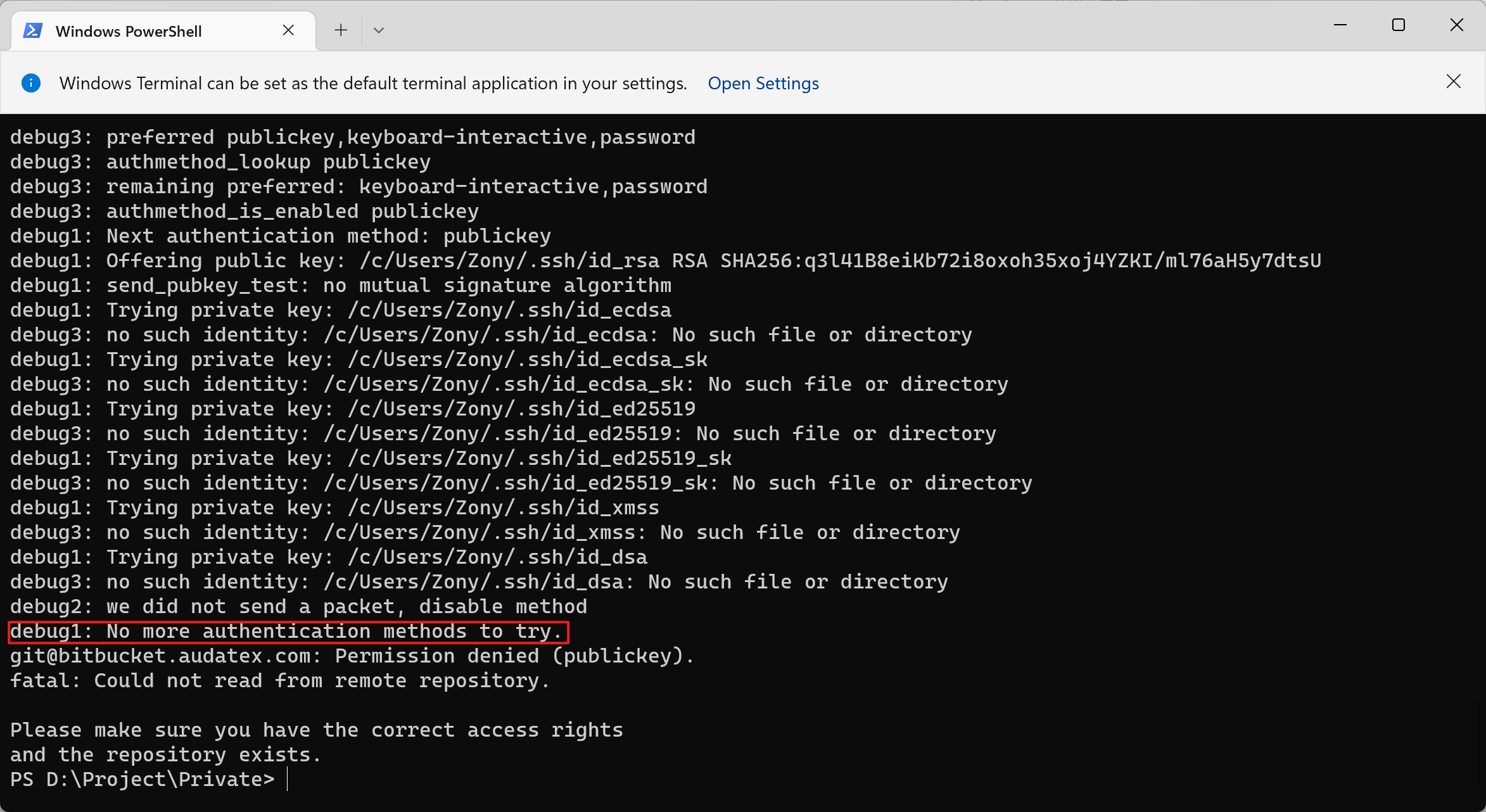
- Bitbucket 使用 SSH 拉取仓库失败的问题
- List of domestic database directory
- LeetCode每日一题——30. 串联所有单词的子串
- Leetcode daily question - 710 Random numbers in the blacklist
- 如何使用 DataAnt 监控 Apache APISIX
- Ref attribute, props configuration, mixin mixing, plug-in, scoped style
- Definition and precautions of genuine St link/v2 j-link jtag/swd pin
- Lumiprobe non fluorescent alkyne research - dbco NHS ester
- 【激活函数】
猜你喜欢

什么是接口?什么是接口测试?
Bitbucket 使用 SSH 拉取仓库失败的问题

Interface use case design

我也差点“跑路”

An artifact extracted from a well-known software and paid by a group of people

阿里云 MSE 基于 Apache APISIX 的全链路灰度方案实践

Mongodb - replica set and sharding

题解 Pie(POJ3122)超详细易懂的二分入门

Apisik helps Middle East social software realize localized deployment

Lumiprobe proteorange protein gel dye instructions
随机推荐
The blocks problem (uva101) Purple Book p110vector application
Understanding web automated testing
阿里云 MSE 基于 Apache APISIX 的全链路灰度方案实践
LeetCode每日一题——710. 黑名单中的随机数
Apisik helps Middle East social software realize localized deployment
Biovendor free light chain( κ and λ) Test steps of ELISA Kit
Stability summary
Understand the construction of the entire network model
Leetcode daily question - 515 Find the maximum value in each tree row
LeetCode:二叉树展开为链表_114
嵌入式中 动态阿拉伯语字符串 转换 LCD显示字符串【感谢建国雄心】
Postman introduction and installation steps
关于不完全类型的认识
postman简介与安装步骤
Comprehensive evaluation of easy-to-use and powerful PDF reading software: PDF expert, marginnote, liquidtext, notability, goodnotes, Zotero
LeetCode121. 买卖股票的最佳时机
在哪个软件上开户比较安全,开户流程是什么?
LeetCode226. 翻转二叉树
Application of Andy s first dictionary (uva10815) Purple Book p112set
QT 一个控件的坐标怎么相对固定显示在另一个控件上(坐标系)