当前位置:网站首页>【Arduino connects SD card module to realize data reading and writing】
【Arduino connects SD card module to realize data reading and writing】
2022-08-02 04:32:00 【WENJIE Technology】
Arduino 连接 SD The card module realizes data reading and writing
前言
SD 卡或 micro sd 卡,It can pack gigabytes of data,And its size is smaller than a coin.本教程中,我们将 SD 卡模块与 Arduino 连接,实现数据读写.
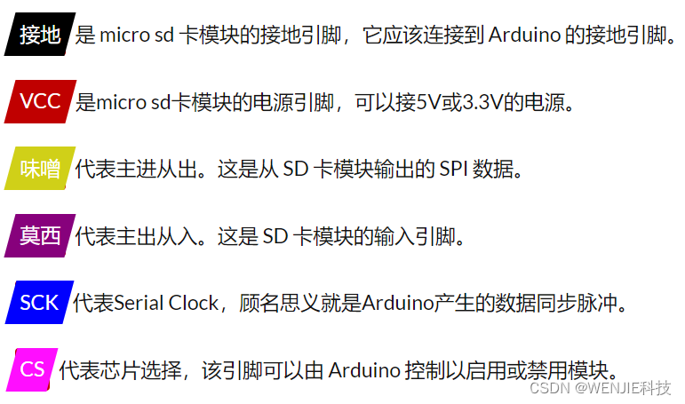
Micro SD Card module pinout
Micro SD The card module has 6 个引脚;它们是 GND、VCC、MISO、MOSI、SCK 和 CS.这个传感器模块的所有引脚都是数字的,除了 VCC 和地.Micro SD The pinout of the card module is shown below: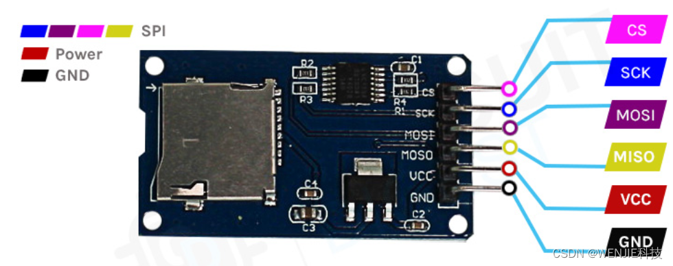
 This is an inexpensive and easy-to-use sensor,Can be used for many different applications.This sensor can be used to read by a microcontroller SD 卡数据.SD The part markings of the card modules are shown below.
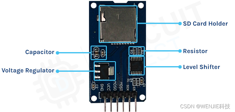 If you look carefully Micro SD 卡模块,PCB Not much in itself.There are only three important components,首先是 Micro SD The deck itself.This bracket allows us to easily switch between different SD exchange between card modules.The second most important is the level shifterIC,因为SDCard module only3.3V上运行,Its maximum operating voltage is 3.6V,So if we directly put SD卡连接到5V,It will definitely killSD卡.此外,The module has an onboard ultra-low dropout voltage regulator,Voltage can be changed from 5V 转换为 3.3V.This is also why this module can be found in 3.3V The reason for working under power.
Micro SDCard module circuit diagram
The module is made of very versatile and easy-to-use components.Micro SD The schematic diagram of the card module is shown below.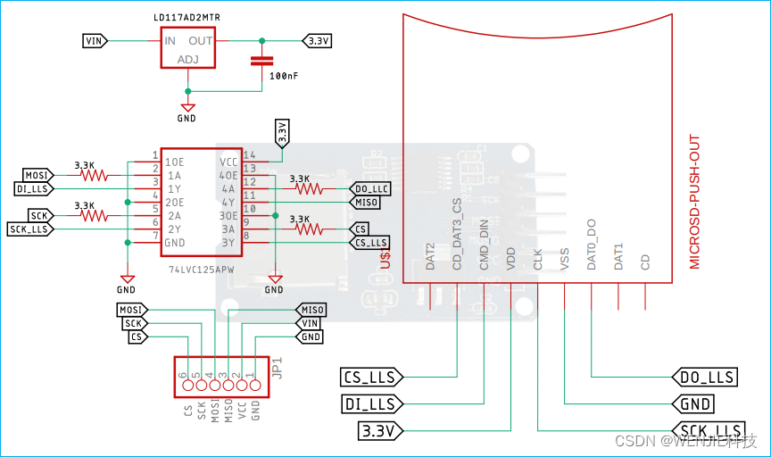 正如您在上面的示意图中看到的,我们有一个 Micro SD 卡连接器,It is a push-out connector,This connector connects to a logic level translator IC.The maximum operating voltage of the module is 3.6V,Hence the logic level converter IC 变得非常重要.为了给 SD Cards and logic level converters are powered,我们使用了 LM1117 LDO,That's why this module can be found in 3.3V 和 5V The reason for working at logic levels.Connectors at the bottom of the schematic JP1 代表 micro SD Connector on the bottom of the card module.
Arduino Micro SDCard module circuit connection diagram
现在我们已经完全了解了 Micro SD How the card module works,We can connect all needed wires to Arduino 并编写代码以从传感器中获取所有数据.Micro SD卡模块与Arduino的连接图如下所示 -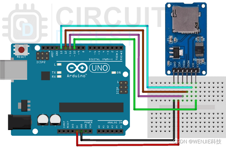 将 Micro SD Card module is connected to Arduino UNO 非常简单,我们只需将 SCK、MISO 和 MOSI 的 SPI 线连接到 SCK(D13)、MOSI(D12) 和 MISO( D11) 如果 SPI 总线上连接了多个设备,那么我们还需要将 CS 线连接到 Arduino.除此之外,VCC and ground are used to power the device.
Arduino 代码说明
Arduino 从 SD The card module reads and writes data as shown below.代码非常简单易懂.The code checks to see if the filename exists“data_log.txt” ,如果文件存在,Then continue to write the given information SD 卡,如果不存在,代码将在 SD Create a file in the card,然后将数据写入SD卡.We can open the file later and check if the content has been written.
我们通过定义 SD The library starts our code,We also declare the module'schipSelect引脚,Next we define a filetype variable and name itmyFile.
#include <SD.h>
const int chipSelect = 10;
File myFile;
接下来,我们有我们的设置功能;在 setup 函数中,We initialize the serial port for debugging.我们还检查 SD card is properly connected to Arduino 的 SPI 引脚.
  // Open serial communications and wait for port to open:
  Serial.begin(9600);
  // wait for Serial Monitor to connect. Needed for native USB port boards only:
  while (!Serial);
接下来,我们创建了一个名为“check_and_create_file()”的函数. 在该函数中,我们检查 SD exists in the carddata_log.txt文件,如果该文件存在,We will continue to execute our code,如果不存在,then we will create the file.要在 SD 卡上创建文件,You just turn it on and off very quickly,不会有任何延迟,文件就会被创建.
void check_and_create_file()
{

  Serial.print("Initializing SD card...");

  if (!SD.begin(chipSelect)) {

    Serial.println("initialization failed!");
    while (1);
  }
  Serial.println("initialization done.");
  if (SD.exists("data_log.txt"))
    Serial.println("data_log.txt exists.");
  else
  {

    Serial.println("data_log.txt doesn't exist.");

    Serial.println("Creating data_log.txt...");
    myFile = SD.open("data_log.txt", FILE_WRITE);
    myFile.close();

    if (SD.exists("data_log.txt"))
      Serial.println("data_log.txt exists.");
    else
      Serial.println("data_log.txt doesn't exist.");
  }
}
接下来,我们将向 SD The card writes some text,and read that text back into the Serial Monitor window.This way we know that the text was successfully written SD 卡.我们创建了一个名为read_write_sd_text()的函数,It does this automatically.Just call this function and it's done.
在函数内部,我们打开一个
void read_write_sd_text()
{

  myFile = SD.open("data_log.txt", FILE_WRITE);
  // if the file opened okay, write to it:
  if (myFile) {

    Serial.print("Writing to data_log.txt...");
    myFile.println("Testing Data Write 1, 2, 3.");
    // close the file:
    myFile.close();
    Serial.println("done.");
  } else {

    // if the file didn't open, print an error:
    Serial.println("error opening data_log.txt");
  }
  // re-open the file for reading:
  myFile = SD.open("data_log.txt");
  if (myFile) {

    Serial.println("data_log.txt:");
    // read from the file until there's nothing else in it:
    while (myFile.available()) {

      Serial.write(myFile.read());
    }
    // close the file:
    myFile.close();
  } else {

    // if the file didn't open, print an error:
    Serial.println("error opening data_log.txt");
  }
}
模块的工作
我们编写了 arduino 代码,以便在 arduino After initialization the code checks to see if it can be found SD 卡.如果找到 SD 卡,It will check if the text file exists,如果文件存在,代码将继续,如果不存在,The code will simply create a new text file,一旦完成,It will write tests 1、2、3 .text file inside.接下来,The code will read the text file and print the data in the text to the serial monitor window.
边栏推荐
猜你喜欢


随机推荐
案例|工业物联网解决方案·智慧钢厂高性能安全数采
C# 关键字学习手记
Binder机制详解(二)
kotlin语法总结(二)
Glide使用及原理分析
【Arduino 连接 SD 卡模块实现数据读写】
Arduino D1----Mlx90614红外温度传感器接线和安装包
Spark MLlib特征处理 之 StringIndexer、IndexToString使用说明以及源码剖析
关于我的大创、论文~
View的滑动
ontop-vkg 学习1
倍福ET2000侦听器使用
[Popular Science Post] I2C Communication Protocol Detailed Explanation - Partial Software Analysis and Logic Analyzer Example Analysis
十大实用的办公工具网站,可以解决你日常100%的问题
PCB设计思路
物联网方案
Nest 的实现原理?理解了 reflect metadata 就懂了
Temporal Segment Networks:Towards Good Practices for Deep TSN论文精读笔记
深度学习实战(1):花的分类任务
Temporal action localization in untrimmed videos via Multi-stage CNNs SCNN论文阅读笔记