当前位置:网站首页>STM32 ADC和DMA
STM32 ADC和DMA
2022-07-07 07:48:00 【小李干净又卫生】
STM32 ADC和DMA简单总结
1.简介
使用野火开发板F429IGT6
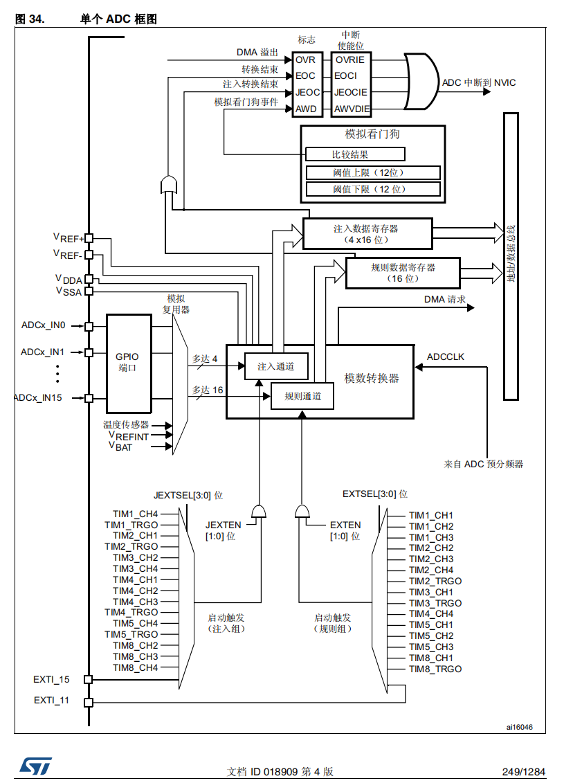
ADC框图
![[外链图片转存失败,源站可能有防盗链机制,建议将图片保存下来直接上传(img-hcRJQP6A-1656898707918)(https://raw.githubusercontent.com/Master-4869/pictures/main/image-20220702105905661.png)]](/img/ac/00d3ebde6e95b5c95a3850dacfac9d.png)
ADC主要的选项配置有
- 时钟的分频配置,这个决定了ADC的时钟速度,
- 采样时钟数量,采样的时间长一点会更准,整个一个采样的周期是采样时间加上转换时间,如果使用12位的就需要加上12个时钟的转换时间,这样3个采样时间加上12个转换时间,整个采样周期就是15个周期
- 数据对齐的方式为左对齐还是右对齐,因为数据寄存器的宽度是16位的,采样的精度只能12位
- 扫描模式是同一个ADC开启多个通道,是否要轮流转换每个通道
- 连续采样是ADC是否要一直采样转换还是触发一次就停止转换
- EOC是转换结束标志
- 可以配置ADC的触发是软件触发还是硬件触发
- rank可以配置各个通道的转换先后顺序
- ADC可以分为规则转换通道和注入转换通道,一般用的就是规则转换通道
ADC还可以配置为多重采样的模式,一共有3个ADC,可以轮流来采样转换同一个通道,这样在第一个ADC转换的时候第二个可以紧接着采样,可以提升ADC的采样率。
![[外链图片转存失败,源站可能有防盗链机制,建议将图片保存下来直接上传(img-2GFsNAoN-1656898707918)(https://raw.githubusercontent.com/Master-4869/pictures/main/image-20220702111226199.png)]](/img/e7/1425db0a500e93bbfc7cfdab172fa5.png)
将3个ADC的相同通道选中,在ADC1的模式中选择三重采样。配置DMA以ADC1为主,其他ADC不需要配置,每个ADC都要打开循环检测模式。
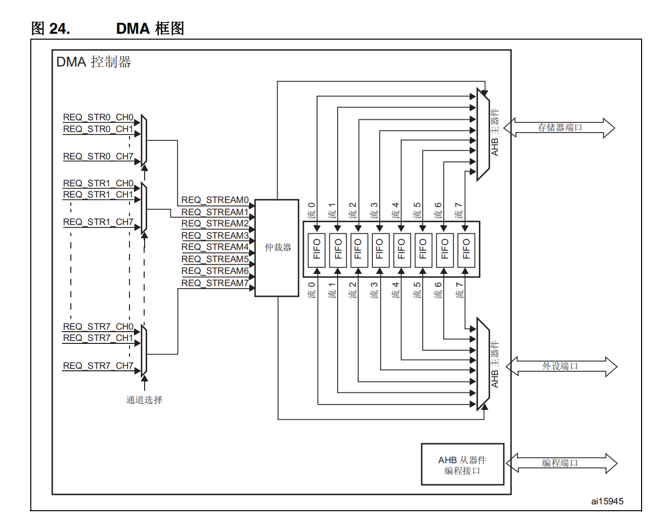

DMA的配置主要有
- 数据传输的方向,分为存储器到存储器,外设到存储器,存储器到外设
- 传输的模式是循环传输还是只传输一次
- 传输数据的宽度
- 传输时外设寄存器的地址和存储器的地址要不要递增,注意每次递增的地址的大小是和设置的数据宽度相同的
如果使用FIFO的话可以设置突发模式等
2.代码
使用cubemx6.6.0
MDK5.34
2.1多通道DMA
/* USER CODE BEGIN Header */
/** ****************************************************************************** * @file adc.c * @brief This file provides code for the configuration * of the ADC instances. ****************************************************************************** * @attention * * Copyright (c) 2022 STMicroelectronics. * All rights reserved. * * This software is licensed under terms that can be found in the LICENSE file * in the root directory of this software component. * If no LICENSE file comes with this software, it is provided AS-IS. * ****************************************************************************** */
/* USER CODE END Header */
/* Includes ------------------------------------------------------------------*/
#include "adc.h"

/* USER CODE BEGIN 0 */

/* USER CODE END 0 */

ADC_HandleTypeDef hadc1;
DMA_HandleTypeDef hdma_adc1;

/* ADC1 init function */
void MX_ADC1_Init(void)
{


  /* USER CODE BEGIN ADC1_Init 0 */

  /* USER CODE END ADC1_Init 0 */

  ADC_ChannelConfTypeDef sConfig = {
    0};

  /* USER CODE BEGIN ADC1_Init 1 */

  /* USER CODE END ADC1_Init 1 */

  /** Configure the global features of the ADC (Clock, Resolution, Data Alignment and number of conversion) */
  hadc1.Instance = ADC1;
  hadc1.Init.ClockPrescaler = ADC_CLOCK_SYNC_PCLK_DIV4;
  hadc1.Init.Resolution = ADC_RESOLUTION_12B;
  hadc1.Init.ScanConvMode = ENABLE;
  hadc1.Init.ContinuousConvMode = ENABLE;
  hadc1.Init.DiscontinuousConvMode = DISABLE;
  hadc1.Init.ExternalTrigConvEdge = ADC_EXTERNALTRIGCONVEDGE_NONE;
  hadc1.Init.ExternalTrigConv = ADC_SOFTWARE_START;
  hadc1.Init.DataAlign = ADC_DATAALIGN_RIGHT;
  hadc1.Init.NbrOfConversion = 3;
  hadc1.Init.DMAContinuousRequests = ENABLE;
  hadc1.Init.EOCSelection = ADC_EOC_SINGLE_CONV;
  if (HAL_ADC_Init(&hadc1) != HAL_OK)
  {

    Error_Handler();
  }

  /** Configure for the selected ADC regular channel its corresponding rank in the sequencer and its sample time. */
  sConfig.Channel = ADC_CHANNEL_13;
  sConfig.Rank = 1;
  sConfig.SamplingTime = ADC_SAMPLETIME_3CYCLES;
  if (HAL_ADC_ConfigChannel(&hadc1, &sConfig) != HAL_OK)
  {

    Error_Handler();
  }

  /** Configure for the selected ADC regular channel its corresponding rank in the sequencer and its sample time. */
  sConfig.Channel = ADC_CHANNEL_4;
  sConfig.Rank = 2;
  if (HAL_ADC_ConfigChannel(&hadc1, &sConfig) != HAL_OK)
  {

    Error_Handler();
  }

  /** Configure for the selected ADC regular channel its corresponding rank in the sequencer and its sample time. */
  sConfig.Channel = ADC_CHANNEL_6;
  sConfig.Rank = 3;
  if (HAL_ADC_ConfigChannel(&hadc1, &sConfig) != HAL_OK)
  {

    Error_Handler();
  }
  /* USER CODE BEGIN ADC1_Init 2 */
  /* USER CODE END ADC1_Init 2 */

}

void HAL_ADC_MspInit(ADC_HandleTypeDef* adcHandle)
{


  GPIO_InitTypeDef GPIO_InitStruct = {
    0};
  if(adcHandle->Instance==ADC1)
  {

  /* USER CODE BEGIN ADC1_MspInit 0 */

  /* USER CODE END ADC1_MspInit 0 */
    /* ADC1 clock enable */
    __HAL_RCC_ADC1_CLK_ENABLE();

    __HAL_RCC_GPIOC_CLK_ENABLE();
    __HAL_RCC_GPIOA_CLK_ENABLE();
    /**ADC1 GPIO Configuration PC3 ------> ADC1_IN13 PA4 ------> ADC1_IN4 PA6 ------> ADC1_IN6 */
    GPIO_InitStruct.Pin = GPIO_PIN_3;
    GPIO_InitStruct.Mode = GPIO_MODE_ANALOG;
    GPIO_InitStruct.Pull = GPIO_NOPULL;
    HAL_GPIO_Init(GPIOC, &GPIO_InitStruct);

    GPIO_InitStruct.Pin = GPIO_PIN_4|GPIO_PIN_6;
    GPIO_InitStruct.Mode = GPIO_MODE_ANALOG;
    GPIO_InitStruct.Pull = GPIO_NOPULL;
    HAL_GPIO_Init(GPIOA, &GPIO_InitStruct);

    /* ADC1 DMA Init */
    /* ADC1 Init */
    hdma_adc1.Instance = DMA2_Stream0;
    hdma_adc1.Init.Channel = DMA_CHANNEL_0;
    hdma_adc1.Init.Direction = DMA_PERIPH_TO_MEMORY;
    hdma_adc1.Init.PeriphInc = DMA_PINC_DISABLE;
    hdma_adc1.Init.MemInc = DMA_MINC_ENABLE;
    hdma_adc1.Init.PeriphDataAlignment = DMA_PDATAALIGN_HALFWORD;
    hdma_adc1.Init.MemDataAlignment = DMA_MDATAALIGN_HALFWORD;
    hdma_adc1.Init.Mode = DMA_CIRCULAR;
    hdma_adc1.Init.Priority = DMA_PRIORITY_LOW;
    hdma_adc1.Init.FIFOMode = DMA_FIFOMODE_DISABLE;
    if (HAL_DMA_Init(&hdma_adc1) != HAL_OK)
    {

      Error_Handler();
    }

    __HAL_LINKDMA(adcHandle,DMA_Handle,hdma_adc1);

  /* USER CODE BEGIN ADC1_MspInit 1 */

  /* USER CODE END ADC1_MspInit 1 */
  }
}

void HAL_ADC_MspDeInit(ADC_HandleTypeDef* adcHandle)
{


  if(adcHandle->Instance==ADC1)
  {

  /* USER CODE BEGIN ADC1_MspDeInit 0 */

  /* USER CODE END ADC1_MspDeInit 0 */
    /* Peripheral clock disable */
    __HAL_RCC_ADC1_CLK_DISABLE();

    /**ADC1 GPIO Configuration PC3 ------> ADC1_IN13 PA4 ------> ADC1_IN4 PA6 ------> ADC1_IN6 */
    HAL_GPIO_DeInit(GPIOC, GPIO_PIN_3);

    HAL_GPIO_DeInit(GPIOA, GPIO_PIN_4|GPIO_PIN_6);

    /* ADC1 DMA DeInit */
    HAL_DMA_DeInit(adcHandle->DMA_Handle);
  /* USER CODE BEGIN ADC1_MspDeInit 1 */

  /* USER CODE END ADC1_MspDeInit 1 */
  }
}

/* USER CODE BEGIN 1 */
//void HAL_ADC_ConvCpltCallback(ADC_HandleTypeDef* hadc)
//{

// ADC_Value = HAL_ADC_GetValue(hadc);

//}
/* USER CODE END 1 */
/* USER CODE BEGIN Header */
/** ****************************************************************************** * @file : main.c * @brief : Main program body ****************************************************************************** * @attention * * Copyright (c) 2022 STMicroelectronics. * All rights reserved. * * This software is licensed under terms that can be found in the LICENSE file * in the root directory of this software component. * If no LICENSE file comes with this software, it is provided AS-IS. * ****************************************************************************** */
/* USER CODE END Header */
/* Includes ------------------------------------------------------------------*/
#include "main.h"
#include "adc.h"
#include "dma.h"
#include "usart.h"
#include "gpio.h"

/* Private includes ----------------------------------------------------------*/
/* USER CODE BEGIN Includes */

/* USER CODE END Includes */

/* Private typedef -----------------------------------------------------------*/
/* USER CODE BEGIN PTD */

/* USER CODE END PTD */

/* Private define ------------------------------------------------------------*/
/* USER CODE BEGIN PD */
/* USER CODE END PD */

/* Private macro -------------------------------------------------------------*/
/* USER CODE BEGIN PM */

/* USER CODE END PM */

/* Private variables ---------------------------------------------------------*/

/* USER CODE BEGIN PV */
__IO uint16_t ADC_Value[300];
//extern UART_HandleTypeDef huart1;
/* USER CODE END PV */

/* Private function prototypes -----------------------------------------------*/
void SystemClock_Config(void);
/* USER CODE BEGIN PFP */

/* USER CODE END PFP */

/* Private user code ---------------------------------------------------------*/
/* USER CODE BEGIN 0 */

/* USER CODE END 0 */

/** * @brief The application entry point. * @retval int */
int main(void)
{

  /* USER CODE BEGIN 1 */

  /* USER CODE END 1 */

  /* MCU Configuration--------------------------------------------------------*/

  /* Reset of all peripherals, Initializes the Flash interface and the Systick. */
  HAL_Init();

  /* USER CODE BEGIN Init */
	uint32_t chanel_value[3] = {
    0};
  /* USER CODE END Init */

  /* Configure the system clock */
  SystemClock_Config();

  /* USER CODE BEGIN SysInit */

  /* USER CODE END SysInit */

  /* Initialize all configured peripherals */
  MX_GPIO_Init();
  MX_DMA_Init();
  MX_ADC1_Init();
  MX_USART1_UART_Init();
  /* USER CODE BEGIN 2 */
	if (HAL_ADC_Start_DMA(&hadc1,(uint32_t *)&ADC_Value,300) == HAL_OK)
	{

		printf("dma开启成功\n\r");

	}
	else
		printf("dma开启失败\n\r");
  /* USER CODE END 2 */

  /* Infinite loop */
  /* USER CODE BEGIN WHILE */
  while (1)
  {

		chanel_value[0] = 0;
		chanel_value[1] = 0;
		chanel_value[2] = 0;
		for(int i = 0;i<300;)
		{

			chanel_value[0] += ADC_Value[i++];
			chanel_value[1] += ADC_Value[i++];
			chanel_value[2] += ADC_Value[i++];
		}
		chanel_value[0] = (float)chanel_value[0]/100;
		chanel_value[1] = (float)chanel_value[1]/100;
		chanel_value[2] = (float)chanel_value[2]/100;
		printf("\r\n------ ADC DMA ------\r\n\r\n");
    printf(" AD1 value = %1.3fV \r\n", chanel_value[0]*3.3f/4096);
    printf(" AD2 value = %1.3fV \r\n", chanel_value[1]*3.3f/4096);
		printf(" AD3 value = %1.3fV \r\n", chanel_value[2]*3.3f/4096);


		HAL_Delay(100);
    /* USER CODE END WHILE */

    /* USER CODE BEGIN 3 */
  }
  /* USER CODE END 3 */
}

/** * @brief System Clock Configuration * @retval None */
void SystemClock_Config(void)
{

  RCC_OscInitTypeDef RCC_OscInitStruct = {
    0};
  RCC_ClkInitTypeDef RCC_ClkInitStruct = {
    0};

  /** Configure the main internal regulator output voltage */
  __HAL_RCC_PWR_CLK_ENABLE();
  __HAL_PWR_VOLTAGESCALING_CONFIG(PWR_REGULATOR_VOLTAGE_SCALE1);

  /** Initializes the RCC Oscillators according to the specified parameters * in the RCC_OscInitTypeDef structure. */
  RCC_OscInitStruct.OscillatorType = RCC_OSCILLATORTYPE_HSE;
  RCC_OscInitStruct.HSEState = RCC_HSE_ON;
  RCC_OscInitStruct.PLL.PLLState = RCC_PLL_ON;
  RCC_OscInitStruct.PLL.PLLSource = RCC_PLLSOURCE_HSE;
  RCC_OscInitStruct.PLL.PLLM = 15;
  RCC_OscInitStruct.PLL.PLLN = 216;
  RCC_OscInitStruct.PLL.PLLP = RCC_PLLP_DIV2;
  RCC_OscInitStruct.PLL.PLLQ = 4;
  if (HAL_RCC_OscConfig(&RCC_OscInitStruct) != HAL_OK)
  {

    Error_Handler();
  }

  /** Activate the Over-Drive mode */
  if (HAL_PWREx_EnableOverDrive() != HAL_OK)
  {

    Error_Handler();
  }

  /** Initializes the CPU, AHB and APB buses clocks */
  RCC_ClkInitStruct.ClockType = RCC_CLOCKTYPE_HCLK|RCC_CLOCKTYPE_SYSCLK
                              |RCC_CLOCKTYPE_PCLK1|RCC_CLOCKTYPE_PCLK2;
  RCC_ClkInitStruct.SYSCLKSource = RCC_SYSCLKSOURCE_PLLCLK;
  RCC_ClkInitStruct.AHBCLKDivider = RCC_SYSCLK_DIV1;
  RCC_ClkInitStruct.APB1CLKDivider = RCC_HCLK_DIV4;
  RCC_ClkInitStruct.APB2CLKDivider = RCC_HCLK_DIV2;

  if (HAL_RCC_ClockConfig(&RCC_ClkInitStruct, FLASH_LATENCY_5) != HAL_OK)
  {

    Error_Handler();
  }
}

/* USER CODE BEGIN 4 */

/* USER CODE END 4 */

/** * @brief This function is executed in case of error occurrence. * @retval None */
void Error_Handler(void)
{

  /* USER CODE BEGIN Error_Handler_Debug */
  /* User can add his own implementation to report the HAL error return state */
  __disable_irq();
  while (1)
  {

  }
  /* USER CODE END Error_Handler_Debug */
}

#ifdef USE_FULL_ASSERT
/** * @brief Reports the name of the source file and the source line number * where the assert_param error has occurred. * @param file: pointer to the source file name * @param line: assert_param error line source number * @retval None */
void assert_failed(uint8_t *file, uint32_t line)
{

  /* USER CODE BEGIN 6 */
  /* User can add his own implementation to report the file name and line number, ex: printf("Wrong parameters value: file %s on line %d\r\n", file, line) */
  /* USER CODE END 6 */
}
#endif /* USE_FULL_ASSERT */
HAL_ADC_Start_DMA函数的作用就是启动ADC并且使用DMA传输数据。后面跟的数据长度要和自己设定的缓冲区长度一致,DMA会自动递增地址存放数据,递增设置的长度之后会自动复位地址重新开始从第一个地址写数据,覆盖掉之前的数据。
ADC规则通道只有一个数据寄存器, ADC_DR,在使能 DMA 模式的情况下(ADC_CR2 寄存器中的 DMA 位置 1),每完成规则通道组中的 一个通道转换后,都会生成一个 DMA 请求。这样便可将转换的数据从 ADC_DR 寄存器传输 到用软件选择的目标位置。
2.2三重ADC
/* USER CODE BEGIN Header */
/** ****************************************************************************** * @file adc.c * @brief This file provides code for the configuration * of the ADC instances. ****************************************************************************** * @attention * * Copyright (c) 2022 STMicroelectronics. * All rights reserved. * * This software is licensed under terms that can be found in the LICENSE file * in the root directory of this software component. * If no LICENSE file comes with this software, it is provided AS-IS. * ****************************************************************************** */
/* USER CODE END Header */
/* Includes ------------------------------------------------------------------*/
#include "adc.h"

/* USER CODE BEGIN 0 */

/* USER CODE END 0 */

ADC_HandleTypeDef hadc1;
ADC_HandleTypeDef hadc2;
ADC_HandleTypeDef hadc3;
DMA_HandleTypeDef hdma_adc1;

/* ADC1 init function */
void MX_ADC1_Init(void)
{


  /* USER CODE BEGIN ADC1_Init 0 */

  /* USER CODE END ADC1_Init 0 */

  ADC_MultiModeTypeDef multimode = {
    0};
  ADC_ChannelConfTypeDef sConfig = {
    0};

  /* USER CODE BEGIN ADC1_Init 1 */

  /* USER CODE END ADC1_Init 1 */

  /** Configure the global features of the ADC (Clock, Resolution, Data Alignment and number of conversion) */
  hadc1.Instance = ADC1;
  hadc1.Init.ClockPrescaler = ADC_CLOCK_SYNC_PCLK_DIV4;
  hadc1.Init.Resolution = ADC_RESOLUTION_12B;
  hadc1.Init.ScanConvMode = DISABLE;
  hadc1.Init.ContinuousConvMode = ENABLE;
  hadc1.Init.DiscontinuousConvMode = DISABLE;
  hadc1.Init.ExternalTrigConvEdge = ADC_EXTERNALTRIGCONVEDGE_NONE;
  hadc1.Init.ExternalTrigConv = ADC_SOFTWARE_START;
  hadc1.Init.DataAlign = ADC_DATAALIGN_RIGHT;
  hadc1.Init.NbrOfConversion = 1;
  hadc1.Init.DMAContinuousRequests = ENABLE;
  hadc1.Init.EOCSelection = ADC_EOC_SINGLE_CONV;
  if (HAL_ADC_Init(&hadc1) != HAL_OK)
  {

    Error_Handler();
  }

  /** Configure the ADC multi-mode */
  multimode.Mode = ADC_TRIPLEMODE_INTERL;
  multimode.DMAAccessMode = ADC_DMAACCESSMODE_2;
  multimode.TwoSamplingDelay = ADC_TWOSAMPLINGDELAY_5CYCLES;
  if (HAL_ADCEx_MultiModeConfigChannel(&hadc1, &multimode) != HAL_OK)
  {

    Error_Handler();
  }

  /** Configure for the selected ADC regular channel its corresponding rank in the sequencer and its sample time. */
  sConfig.Channel = ADC_CHANNEL_13;
  sConfig.Rank = 1;
  sConfig.SamplingTime = ADC_SAMPLETIME_3CYCLES;
  if (HAL_ADC_ConfigChannel(&hadc1, &sConfig) != HAL_OK)
  {

    Error_Handler();
  }
  /* USER CODE BEGIN ADC1_Init 2 */

  /* USER CODE END ADC1_Init 2 */

}
/* ADC2 init function */
void MX_ADC2_Init(void)
{


  /* USER CODE BEGIN ADC2_Init 0 */

  /* USER CODE END ADC2_Init 0 */

  ADC_ChannelConfTypeDef sConfig = {
    0};

  /* USER CODE BEGIN ADC2_Init 1 */

  /* USER CODE END ADC2_Init 1 */

  /** Configure the global features of the ADC (Clock, Resolution, Data Alignment and number of conversion) */
  hadc2.Instance = ADC2;
  hadc2.Init.ClockPrescaler = ADC_CLOCK_SYNC_PCLK_DIV4;
  hadc2.Init.Resolution = ADC_RESOLUTION_12B;
  hadc2.Init.ScanConvMode = DISABLE;
  hadc2.Init.ContinuousConvMode = ENABLE;
  hadc2.Init.DiscontinuousConvMode = DISABLE;
  hadc2.Init.DataAlign = ADC_DATAALIGN_RIGHT;
  hadc2.Init.NbrOfConversion = 1;
  hadc2.Init.DMAContinuousRequests = DISABLE;
  hadc2.Init.EOCSelection = ADC_EOC_SINGLE_CONV;
  if (HAL_ADC_Init(&hadc2) != HAL_OK)
  {

    Error_Handler();
  }

  /** Configure for the selected ADC regular channel its corresponding rank in the sequencer and its sample time. */
  sConfig.Channel = ADC_CHANNEL_13;
  sConfig.Rank = 1;
  sConfig.SamplingTime = ADC_SAMPLETIME_3CYCLES;
  if (HAL_ADC_ConfigChannel(&hadc2, &sConfig) != HAL_OK)
  {

    Error_Handler();
  }
  /* USER CODE BEGIN ADC2_Init 2 */

  /* USER CODE END ADC2_Init 2 */

}
/* ADC3 init function */
void MX_ADC3_Init(void)
{


  /* USER CODE BEGIN ADC3_Init 0 */

  /* USER CODE END ADC3_Init 0 */

  ADC_ChannelConfTypeDef sConfig = {
    0};

  /* USER CODE BEGIN ADC3_Init 1 */

  /* USER CODE END ADC3_Init 1 */

  /** Configure the global features of the ADC (Clock, Resolution, Data Alignment and number of conversion) */
  hadc3.Instance = ADC3;
  hadc3.Init.ClockPrescaler = ADC_CLOCK_SYNC_PCLK_DIV4;
  hadc3.Init.Resolution = ADC_RESOLUTION_12B;
  hadc3.Init.ScanConvMode = DISABLE;
  hadc3.Init.ContinuousConvMode = ENABLE;
  hadc3.Init.DiscontinuousConvMode = DISABLE;
  hadc3.Init.DataAlign = ADC_DATAALIGN_RIGHT;
  hadc3.Init.NbrOfConversion = 1;
  hadc3.Init.DMAContinuousRequests = DISABLE;
  hadc3.Init.EOCSelection = ADC_EOC_SINGLE_CONV;
  if (HAL_ADC_Init(&hadc3) != HAL_OK)
  {

    Error_Handler();
  }

  /** Configure for the selected ADC regular channel its corresponding rank in the sequencer and its sample time. */
  sConfig.Channel = ADC_CHANNEL_13;
  sConfig.Rank = 1;
  sConfig.SamplingTime = ADC_SAMPLETIME_3CYCLES;
  if (HAL_ADC_ConfigChannel(&hadc3, &sConfig) != HAL_OK)
  {

    Error_Handler();
  }
  /* USER CODE BEGIN ADC3_Init 2 */

  /* USER CODE END ADC3_Init 2 */

}

void HAL_ADC_MspInit(ADC_HandleTypeDef* adcHandle)
{


  GPIO_InitTypeDef GPIO_InitStruct = {
    0};
  if(adcHandle->Instance==ADC1)
  {

  /* USER CODE BEGIN ADC1_MspInit 0 */

  /* USER CODE END ADC1_MspInit 0 */
    /* ADC1 clock enable */
    __HAL_RCC_ADC1_CLK_ENABLE();

    __HAL_RCC_GPIOC_CLK_ENABLE();
    /**ADC1 GPIO Configuration PC3 ------> ADC1_IN13 */
    GPIO_InitStruct.Pin = GPIO_PIN_3;
    GPIO_InitStruct.Mode = GPIO_MODE_ANALOG;
    GPIO_InitStruct.Pull = GPIO_NOPULL;
    HAL_GPIO_Init(GPIOC, &GPIO_InitStruct);

    /* ADC1 DMA Init */
    /* ADC1 Init */
    hdma_adc1.Instance = DMA2_Stream0;
    hdma_adc1.Init.Channel = DMA_CHANNEL_0;
    hdma_adc1.Init.Direction = DMA_PERIPH_TO_MEMORY;
    hdma_adc1.Init.PeriphInc = DMA_PINC_DISABLE;
    hdma_adc1.Init.MemInc = DMA_MINC_ENABLE;
    hdma_adc1.Init.PeriphDataAlignment = DMA_PDATAALIGN_WORD;
    hdma_adc1.Init.MemDataAlignment = DMA_MDATAALIGN_WORD;
    hdma_adc1.Init.Mode = DMA_CIRCULAR;
    hdma_adc1.Init.Priority = DMA_PRIORITY_LOW;
    hdma_adc1.Init.FIFOMode = DMA_FIFOMODE_DISABLE;
    if (HAL_DMA_Init(&hdma_adc1) != HAL_OK)
    {

      Error_Handler();
    }

    __HAL_LINKDMA(adcHandle,DMA_Handle,hdma_adc1);

  /* USER CODE BEGIN ADC1_MspInit 1 */

  /* USER CODE END ADC1_MspInit 1 */
  }
  else if(adcHandle->Instance==ADC2)
  {

  /* USER CODE BEGIN ADC2_MspInit 0 */

  /* USER CODE END ADC2_MspInit 0 */
    /* ADC2 clock enable */
    __HAL_RCC_ADC2_CLK_ENABLE();

    __HAL_RCC_GPIOC_CLK_ENABLE();
    /**ADC2 GPIO Configuration PC3 ------> ADC2_IN13 */
    GPIO_InitStruct.Pin = GPIO_PIN_3;
    GPIO_InitStruct.Mode = GPIO_MODE_ANALOG;
    GPIO_InitStruct.Pull = GPIO_NOPULL;
    HAL_GPIO_Init(GPIOC, &GPIO_InitStruct);

  /* USER CODE BEGIN ADC2_MspInit 1 */

  /* USER CODE END ADC2_MspInit 1 */
  }
  else if(adcHandle->Instance==ADC3)
  {

  /* USER CODE BEGIN ADC3_MspInit 0 */

  /* USER CODE END ADC3_MspInit 0 */
    /* ADC3 clock enable */
    __HAL_RCC_ADC3_CLK_ENABLE();

    __HAL_RCC_GPIOC_CLK_ENABLE();
    /**ADC3 GPIO Configuration PC3 ------> ADC3_IN13 */
    GPIO_InitStruct.Pin = GPIO_PIN_3;
    GPIO_InitStruct.Mode = GPIO_MODE_ANALOG;
    GPIO_InitStruct.Pull = GPIO_NOPULL;
    HAL_GPIO_Init(GPIOC, &GPIO_InitStruct);

  /* USER CODE BEGIN ADC3_MspInit 1 */

  /* USER CODE END ADC3_MspInit 1 */
  }
}

void HAL_ADC_MspDeInit(ADC_HandleTypeDef* adcHandle)
{


  if(adcHandle->Instance==ADC1)
  {

  /* USER CODE BEGIN ADC1_MspDeInit 0 */

  /* USER CODE END ADC1_MspDeInit 0 */
    /* Peripheral clock disable */
    __HAL_RCC_ADC1_CLK_DISABLE();

    /**ADC1 GPIO Configuration PC3 ------> ADC1_IN13 */
    HAL_GPIO_DeInit(GPIOC, GPIO_PIN_3);

    /* ADC1 DMA DeInit */
    HAL_DMA_DeInit(adcHandle->DMA_Handle);
  /* USER CODE BEGIN ADC1_MspDeInit 1 */

  /* USER CODE END ADC1_MspDeInit 1 */
  }
  else if(adcHandle->Instance==ADC2)
  {

  /* USER CODE BEGIN ADC2_MspDeInit 0 */

  /* USER CODE END ADC2_MspDeInit 0 */
    /* Peripheral clock disable */
    __HAL_RCC_ADC2_CLK_DISABLE();

    /**ADC2 GPIO Configuration PC3 ------> ADC2_IN13 */
    HAL_GPIO_DeInit(GPIOC, GPIO_PIN_3);

  /* USER CODE BEGIN ADC2_MspDeInit 1 */

  /* USER CODE END ADC2_MspDeInit 1 */
  }
  else if(adcHandle->Instance==ADC3)
  {

  /* USER CODE BEGIN ADC3_MspDeInit 0 */

  /* USER CODE END ADC3_MspDeInit 0 */
    /* Peripheral clock disable */
    __HAL_RCC_ADC3_CLK_DISABLE();

    /**ADC3 GPIO Configuration PC3 ------> ADC3_IN13 */
    HAL_GPIO_DeInit(GPIOC, GPIO_PIN_3);

  /* USER CODE BEGIN ADC3_MspDeInit 1 */

  /* USER CODE END ADC3_MspDeInit 1 */
  }
}

/* USER CODE BEGIN 1 */

/* USER CODE END 1 */
/* USER CODE BEGIN Header */
/** ****************************************************************************** * @file : main.c * @brief : Main program body ****************************************************************************** * @attention * * Copyright (c) 2022 STMicroelectronics. * All rights reserved. * * This software is licensed under terms that can be found in the LICENSE file * in the root directory of this software component. * If no LICENSE file comes with this software, it is provided AS-IS. * ****************************************************************************** */
/* USER CODE END Header */
/* Includes ------------------------------------------------------------------*/
#include "main.h"
#include "adc.h"
#include "dma.h"
#include "usart.h"
#include "gpio.h"

/* Private includes ----------------------------------------------------------*/
/* USER CODE BEGIN Includes */

/* USER CODE END Includes */

/* Private typedef -----------------------------------------------------------*/
/* USER CODE BEGIN PTD */

/* USER CODE END PTD */

/* Private define ------------------------------------------------------------*/
/* USER CODE BEGIN PD */
uint32_t adc_buffer[300] = {
    0};
/* USER CODE END PD */

/* Private macro -------------------------------------------------------------*/
/* USER CODE BEGIN PM */

/* USER CODE END PM */

/* Private variables ---------------------------------------------------------*/

/* USER CODE BEGIN PV */

/* USER CODE END PV */

/* Private function prototypes -----------------------------------------------*/
void SystemClock_Config(void);
/* USER CODE BEGIN PFP */

/* USER CODE END PFP */

/* Private user code ---------------------------------------------------------*/
/* USER CODE BEGIN 0 */

/* USER CODE END 0 */

/** * @brief The application entry point. * @retval int */
int main(void)
{

  /* USER CODE BEGIN 1 */

  /* USER CODE END 1 */

  /* MCU Configuration--------------------------------------------------------*/

  /* Reset of all peripherals, Initializes the Flash interface and the Systick. */
  HAL_Init();

  /* USER CODE BEGIN Init */

  /* USER CODE END Init */

  /* Configure the system clock */
  SystemClock_Config();

  /* USER CODE BEGIN SysInit */

  /* USER CODE END SysInit */

  /* Initialize all configured peripherals */
  MX_GPIO_Init();
  MX_DMA_Init();
  MX_ADC1_Init();
  MX_ADC2_Init();
  MX_ADC3_Init();
  MX_USART1_UART_Init();
  /* USER CODE BEGIN 2 */
	printf("\r\n------ ADC DMA ------\r\n\r\n");
	HAL_ADC_Start(&hadc3);
	HAL_ADC_Start(&hadc2);
	HAL_ADCEx_MultiModeStart_DMA(&hadc1,adc_buffer,300);

  /* USER CODE END 2 */

  /* Infinite loop */
  /* USER CODE BEGIN WHILE */
  while (1)
  {

    /* USER CODE END WHILE */
		printf("\r\n------ ADC DMA ------\r\n\r\n");
		printf(" AD1 value = %1.3fV \r\n", (uint16_t)adc_buffer[0]*3.3f/4096);
		printf(" AD1 value = %1.3fV \r\n", (adc_buffer[0]>>16)*3.3f/4096);
		printf(" AD1 value = %1.3fV \r\n", (uint16_t)adc_buffer[1]*3.3f/4096);
		printf(" AD1 value = %1.3fV \r\n", (adc_buffer[1]>>16)*3.3f/4096);
		HAL_Delay(100);

    /* USER CODE BEGIN 3 */
  }
  /* USER CODE END 3 */
}

/** * @brief System Clock Configuration * @retval None */
void SystemClock_Config(void)
{

  RCC_OscInitTypeDef RCC_OscInitStruct = {
    0};
  RCC_ClkInitTypeDef RCC_ClkInitStruct = {
    0};

  /** Configure the main internal regulator output voltage */
  __HAL_RCC_PWR_CLK_ENABLE();
  __HAL_PWR_VOLTAGESCALING_CONFIG(PWR_REGULATOR_VOLTAGE_SCALE1);

  /** Initializes the RCC Oscillators according to the specified parameters * in the RCC_OscInitTypeDef structure. */
  RCC_OscInitStruct.OscillatorType = RCC_OSCILLATORTYPE_HSE;
  RCC_OscInitStruct.HSEState = RCC_HSE_ON;
  RCC_OscInitStruct.PLL.PLLState = RCC_PLL_ON;
  RCC_OscInitStruct.PLL.PLLSource = RCC_PLLSOURCE_HSE;
  RCC_OscInitStruct.PLL.PLLM = 15;
  RCC_OscInitStruct.PLL.PLLN = 216;
  RCC_OscInitStruct.PLL.PLLP = RCC_PLLP_DIV2;
  RCC_OscInitStruct.PLL.PLLQ = 4;
  if (HAL_RCC_OscConfig(&RCC_OscInitStruct) != HAL_OK)
  {

    Error_Handler();
  }

  /** Activate the Over-Drive mode */
  if (HAL_PWREx_EnableOverDrive() != HAL_OK)
  {

    Error_Handler();
  }

  /** Initializes the CPU, AHB and APB buses clocks */
  RCC_ClkInitStruct.ClockType = RCC_CLOCKTYPE_HCLK|RCC_CLOCKTYPE_SYSCLK
                              |RCC_CLOCKTYPE_PCLK1|RCC_CLOCKTYPE_PCLK2;
  RCC_ClkInitStruct.SYSCLKSource = RCC_SYSCLKSOURCE_PLLCLK;
  RCC_ClkInitStruct.AHBCLKDivider = RCC_SYSCLK_DIV1;
  RCC_ClkInitStruct.APB1CLKDivider = RCC_HCLK_DIV4;
  RCC_ClkInitStruct.APB2CLKDivider = RCC_HCLK_DIV2;

  if (HAL_RCC_ClockConfig(&RCC_ClkInitStruct, FLASH_LATENCY_5) != HAL_OK)
  {

    Error_Handler();
  }
}

/* USER CODE BEGIN 4 */

/* USER CODE END 4 */

/** * @brief This function is executed in case of error occurrence. * @retval None */
void Error_Handler(void)
{

  /* USER CODE BEGIN Error_Handler_Debug */
  /* User can add his own implementation to report the HAL error return state */
  __disable_irq();
  while (1)
  {

  }
  /* USER CODE END Error_Handler_Debug */
}

#ifdef USE_FULL_ASSERT
/** * @brief Reports the name of the source file and the source line number * where the assert_param error has occurred. * @param file: pointer to the source file name * @param line: assert_param error line source number * @retval None */
void assert_failed(uint8_t *file, uint32_t line)
{

  /* USER CODE BEGIN 6 */
  /* User can add his own implementation to report the file name and line number, ex: printf("Wrong parameters value: file %s on line %d\r\n", file, line) */
  /* USER CODE END 6 */
}
#endif /* USE_FULL_ASSERT */
注意在启动ADC的时候要以下面的顺序开启,DMA是使用ADC1的
	HAL_ADC_Start(&hadc3);
	HAL_ADC_Start(&hadc2);
	HAL_ADCEx_MultiModeStart_DMA(&hadc1,adc_buffer,300);
在多重ADC模式下,可在多模式数据寄存器(ADC_CDR)中读取转换的数据。可在多模式状态寄存器(ADC_CSR)中读取状态位
在三重 ADC 模式下,ADC 通用数据寄存器 (ADC_CDR) 包含 ADC1、ADC2 和 ADC3 的规则转换数据。 按照所选的存储顺序使用全部 32 个寄存器位。
在双重 ADC 模式下,ADC 通用数据寄存器 (ADC_CDR) 包含 ADC1 和 ADC2 的规则转换数据。使用全部 32 个寄存器位。
![[外链图片转存失败,源站可能有防盗链机制,建议将图片保存下来直接上传(img-segkD2js-1656898707919)(https://raw.githubusercontent.com/Master-4869/pictures/main/image-20220702114556931.png)]](/img/73/5da1168b21bb097724351a6f060ed3.png)

3.结果
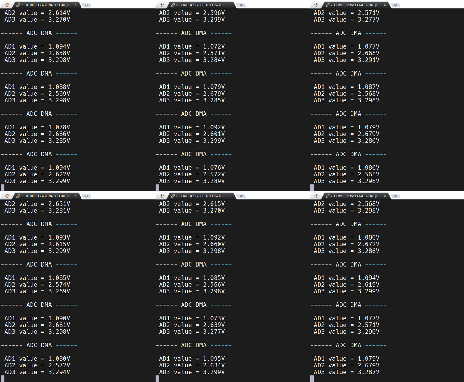
多通道ADC
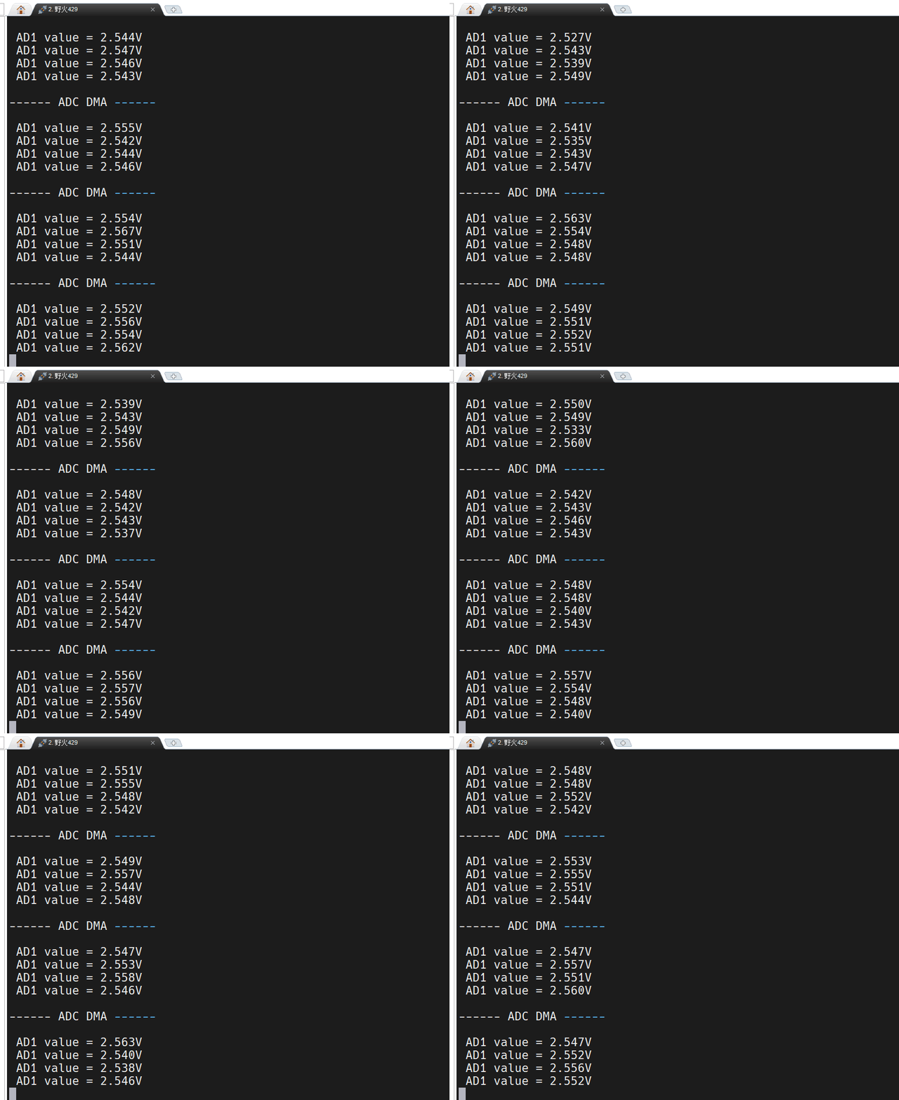
多重ADC
工程文件已上传。
边栏推荐
- [ORM framework]
- 一文讲解单片机、ARM、MUC、DSP、FPGA、嵌入式错综复杂的关系
- 【学习笔记-李宏毅】GAN(生成对抗网络)全系列(一)
- 每周推荐短视频:L2级有哪些我们日常中经常会用到的功能?
- Basic chapter: take you through notes
- The physical meaning of imaginary number J
- Sword finger offer II 107 Distance in matrix
- Parameter sniffing (2/2)
- [original] what is the core of programmer team management?
- The landing practice of ByteDance kitex in SEMA e-commerce scene
猜你喜欢

反卷积通俗详细解析与nn.ConvTranspose2d重要参数解释
Introduction to energy Router: Architecture and functions for energy Internet
Internship log - day04
STM32中AHB总线_APB2总线_APB1总线这些是什么
ISP、IAP、ICP、JTAG、SWD的编程特点

“十二星座女神降临”全新活动推出
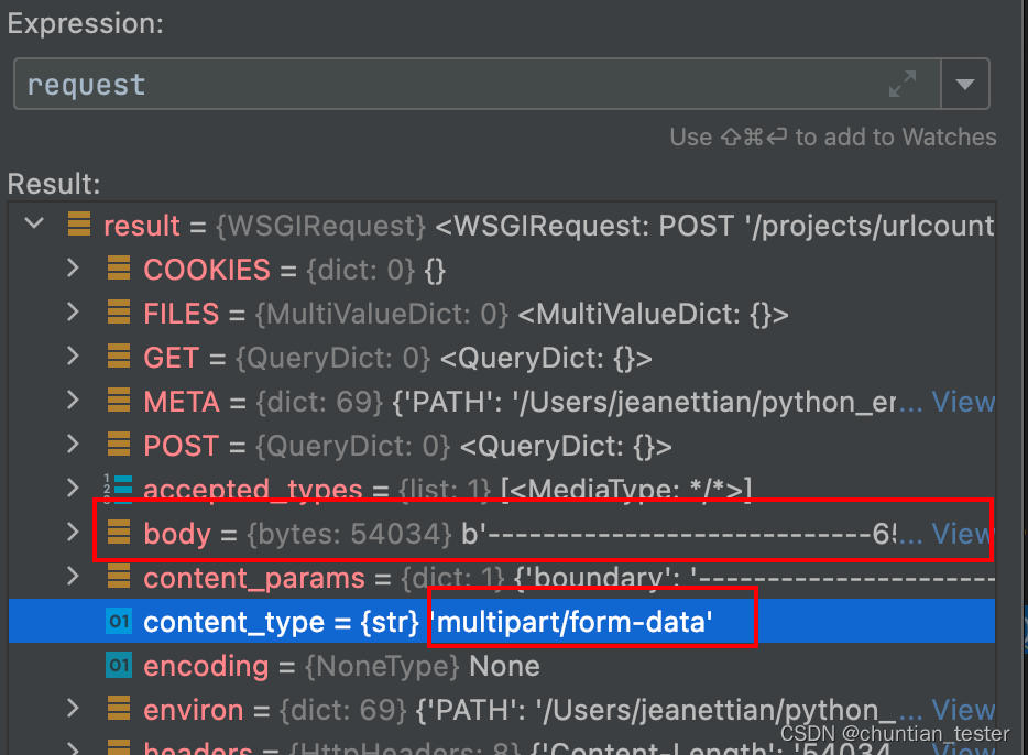
The request object parses the request body and request header parameters

Chris Lattner, père de llvm: Pourquoi reconstruire le logiciel d'infrastructure ai

Pit encountered by vs2015 under win7 (successful)
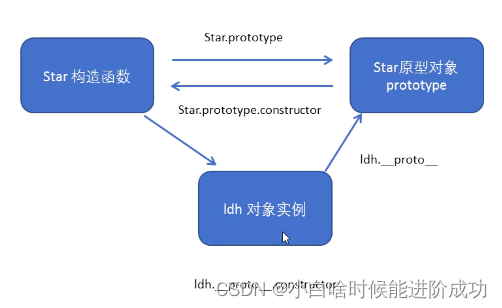
Es classes and objects, prototypes
随机推荐
Flinkcdc failed to collect Oracle in the snapshot stage. How do you adjust this?
企业实战|复杂业务关系下的银行业运维指标体系建设
喜马拉雅网页版每次暂停后弹窗推荐下载客户端解决办法
终于可以一行代码也不用改了!ShardingSphere 原生驱动问世
This article explains the complex relationship between MCU, arm, muc, DSP, FPGA and embedded system
内存==c语言1
Some thoughts on the testing work in the process of R & D
Can I open a stock trading account online? Is it safe
Hcip first day notes sorting
LeetCode 练习——113. 路径总和 II
Three years after graduation
Postman tutorial - scripting
视频化全链路智能上云?一文详解什么是阿里云视频云「智能媒体生产」
Official media attention! The list of top 100 domestic digital collection platforms was released, and the industry accelerated the healthy development of compliance
Analyze Android event distribution mechanism according to popular interview questions (I)
Delete a record in the table in pl/sql by mistake, and the recovery method
ORM模型--关联字段,抽象模型类
MCU is the most popular science (ten thousand words summary, worth collecting)
Postman interface test IV
单片机(MCU)最强科普(万字总结,值得收藏)