当前位置:网站首页>[Key shake elimination] development of key shake elimination module based on FPGA
[Key shake elimination] development of key shake elimination module based on FPGA
2022-07-06 03:49:00 【FPGA and MATLAB】
1. Software version
QUARTUSII8.1
Modelsim6.5d
2. System source code
module tops(
            i_clk,    //100M
            i_rst,    // System reset function , High level reset , If you don't use this corner , Then a direct low level is enough
            i_input1, // Key in 1
            i_input2, // Key in 2
            o_output1,// Pulse output 1
            o_output2,// Pulse output 2
            test_cnt1,// Test counter 1
            test_cnt2,// Test counter 2
            test_enable1,// Test enable signal
            test_enable2 // Test enable signal
           );

//100M be equal to 10ns, therefore 1s The middle is 10_000_000 individual 100M Clock cycle
// When simulating , In order to see the simulation effect conveniently , So will 10_000_000 Change to a smaller value 10_000
//parameter NUM = 32'd10000000;  // Practical use
parameter NUM = 32'd100;       // For simulation


input       i_clk;//100M by 10ns
input       i_rst;
input       i_input1;
input       i_input2;

output      o_output1;
output      o_output2;
output[31:0]test_cnt1;
output[31:0]test_cnt2;
output      test_enable1;
output      test_enable2;


reg      o_output1    = 1'b0;
reg      o_output2    = 1'b0;
reg      test_enable1 = 1'b0;
reg      test_enable2 = 1'b0;
reg[31:0]cnt1         = 32'd0;
reg[31:0]cnt2         = 32'd0;


reg      flag1        = 1'b1;
reg      flag2        = 1'b1;


always @(posedge i_clk or posedge i_rst)// Deal with the main process
begin
     if(i_rst)// System reset
     begin
     test_enable1 <= 1'b0;// Define enable signal
     test_enable2 <= 1'b0;// Define enable signal
     cnt1         <= 32'd0;
     cnt2         <= 32'd0;
     flag1        <= 1'b1;
     flag2        <= 1'b1;
     end
else begin
          if(i_input1 == 1'b0 & i_input2 == 1'b1 & flag1 == 1'b1)// Press the button 1, Do not press the key 2
          begin
               //1s The clock can maintain 10_000_000 Clock cycles

               cnt2 <= 32'd0;

               if(cnt1 < NUM)// Less than 1s
               begin
               cnt1 <= cnt1 + 32'd1;
               test_enable1 <= 1'b1;// Output 1 Pulse ,// After pressing the button , continued 1s The clock
               test_enable2 <= 1'b0;
               flag1        <= 1'b1;// Used to mask the second button
               flag2        <= 1'b0;// Used to mask the second button
               end

               if(cnt1 == NUM)// To 1s, Stop output
               begin
               cnt1 <= cnt1;
               test_enable1 <= 1'b0;
               test_enable2 <= 1'b0;
               flag1        <= 1'b1;
               flag2        <= 1'b1;
               end
          end


          if(i_input1 == 1'b1 & i_input2 == 1'b0 & flag2 == 1'b1)// Press the button 2, Do not press the key 1
          begin
               //50s The clock can maintain
               cnt1 <= 32'd0;

               if(cnt2 < 50*NUM)// Less than 50s
               begin
               cnt2 <= cnt2 + 32'd1;
               test_enable1 <= 1'b0;// Output 1 Pulse ,// After pressing the button , continued 1s The clock
               test_enable2 <= 1'b1;
               flag1        <= 1'b0;// Used to shield No 1 Button
               flag2        <= 1'b1;// Used to shield No 1 Button
               end

               if(cnt2 == 50*NUM)// To 1s, Stop output
               begin
               cnt2 <= cnt2;
               test_enable1 <= 1'b0;
               test_enable2 <= 1'b0;
               flag1        <= 1'b1;
               flag2        <= 1'b1;
               end
          end


          if(i_input1 == 1'b1 & i_input2 == 1'b1)// No key operation
          begin
          cnt1 <= 32'd0;
          cnt2 <= 32'd0;
          end

     end
end
assign test_cnt1 = cnt1;
assign test_cnt2 = cnt2;

// The following is based on the energy signal , Output pulse

// Define two pulse counters
reg[31:0]pcnt1 = 32'd0;
reg[31:0]pcnt2 = 32'd0;
always @(posedge i_clk or posedge i_rst)// Deal with the main process
begin
     if(i_rst)// System reset
     begin
     pcnt1        <= 32'd0;
     pcnt2        <= 32'd0;
     o_output1    <= 1'b0;
     o_output2    <= 1'b0;
     end
else begin
          if(test_enable1 == 1'b1)//1s Inside one 100ns Pulse of , namely 1s A 10M Pulse signal of
          begin
          pcnt1 <= pcnt1 + 32'd1;

               if(pcnt1 < 32'd10)
               begin
               o_output1    <= 1'b1;// produce 100ns The signal of
               end
          else begin
               o_output1    <= 1'b0;
               end
          end
     else begin
          pcnt1        <= 32'd0;
          o_output1    <= 1'b0;
          end


          if(test_enable2 == 1'b1)//50s Inside 50 individual 100ns Pulse of , namely 1s A 10M Pulse signal of
          begin

               if(pcnt2 == NUM-1)
               begin
               pcnt2 <= 32'd0;
               end
          else begin
               pcnt2 <= pcnt2 + 32'd1;
               end


               if(pcnt2 < 32'd10)
               begin
               o_output2    <= 1'b1;// produce 100ns The signal of
               end
          else begin
               o_output2    <= 1'b0;
               end
          end
     else begin
          pcnt2        <= 32'd0;
          o_output2    <= 1'b0;
          end

     end
end

endmodule
3. Simulation conclusion
QII With simulation instructions :

We locally amplify the waveform :
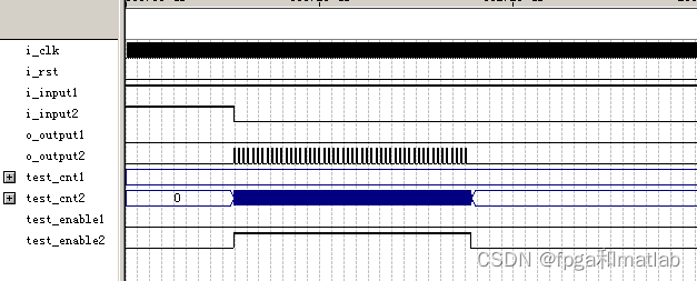
The first part , You can see input1 For the high ,input2 For low , explain 2 Press , therefore output2 Produce continuous 50 Pulse .
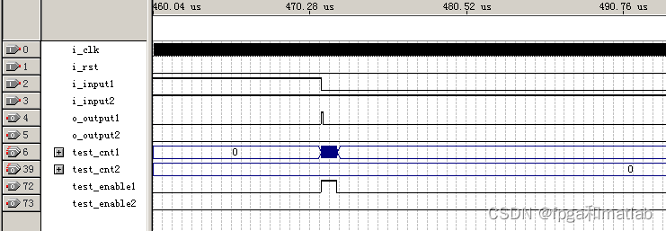
The second part ,input1 For low , The first button is pressed , So only one high-level signal is generated
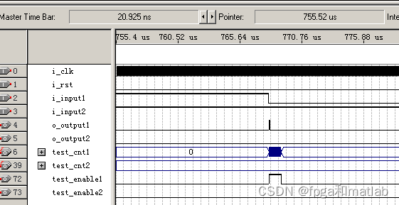
The third part , The first button was pressed , So only one pulse is generated .
Modelsim The simulation shows that :

We will locally magnify the simulation :
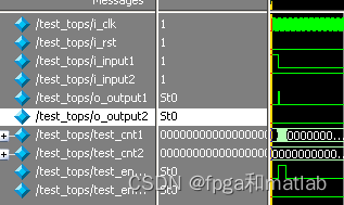
Press the key :

Key two is pressed ;

Or key two is pressed .
A35-09
边栏推荐
- Facebook等大廠超十億用戶數據遭泄露,早該關注DID了
- Factors affecting user perception
- 3分钟带你了解微信小程序开发
- Plus d'un milliard d'utilisateurs de grandes entreprises comme Facebook ont été compromis, il est temps de se concentrer sur le did
- 登录mysql输入密码时报错,ERROR 1045 (28000): Access denied for user ‘root‘@‘localhost‘ (using password: NO/YES
- JS Vanke banner rotation chart JS special effect
- A brief introduction to symbols and link libraries in C language
- Pytorch load data
- [Massey] Massey font format and typesetting requirements
- 遥感图像超分辨率论文推荐
猜你喜欢
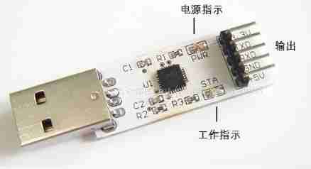
Serial port-rs232-rs485-ttl

WPF effect Article 191 box selection listbox
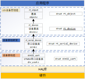
3.1 detailed explanation of rtthread serial port device (V1)
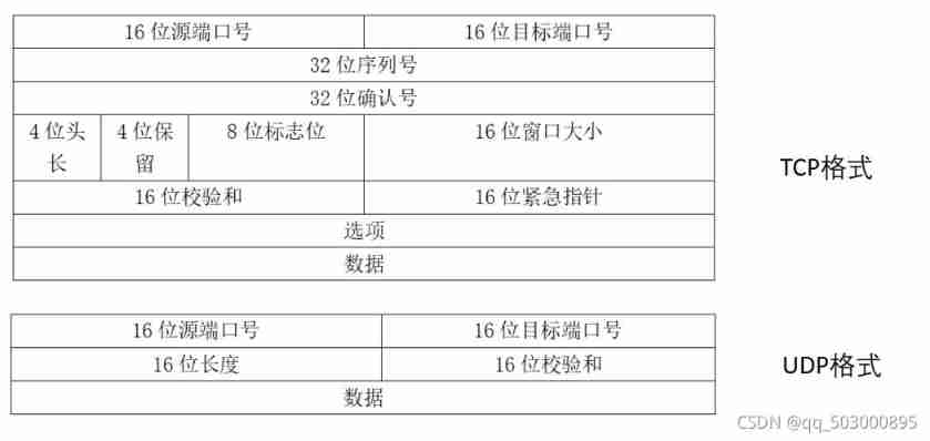
UDP reliable transport protocol (quic)
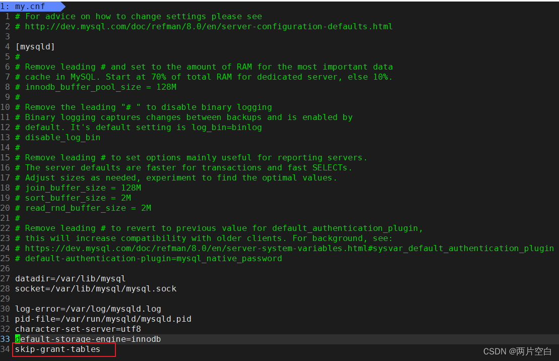
Error 1045 (28000): access denied for user 'root' @ 'localhost' (using password: no/yes
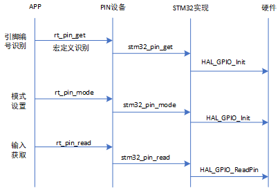
2.2 STM32 GPIO operation
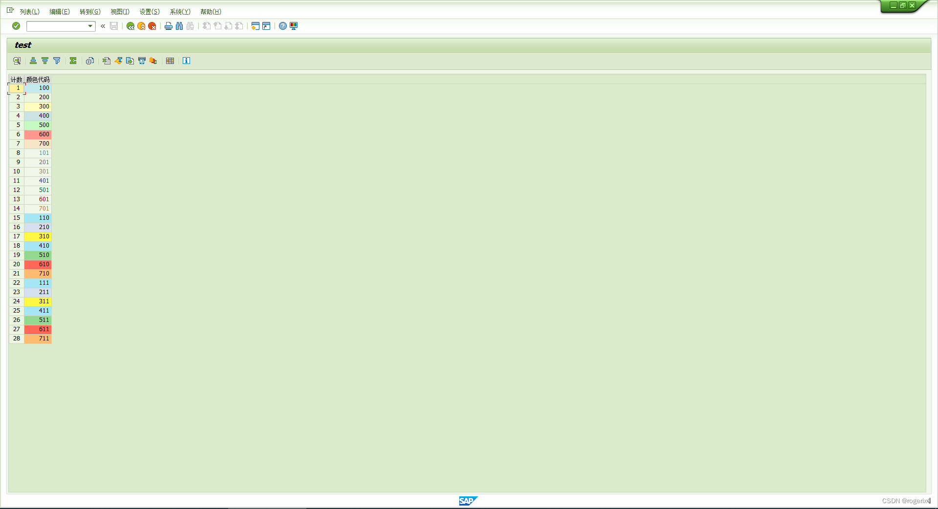
SAP ALV cell level set color

【PSO】基于PSO粒子群优化的物料点货物运输成本最低值计算matlab仿真,包括运输费用、代理人转换费用、运输方式转化费用和时间惩罚费用
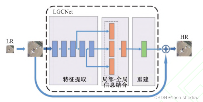
遥感图像超分辨重建综述
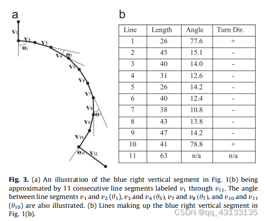
Edcircles: a real time circle detector with a false detection control translation
随机推荐
C language circular statement
2.1 rtthread pin设备详解
给新人工程师组员的建议
Pointer for in-depth analysis (problem solution)
Pointer written test questions ~ approaching Dachang
BUAA calculator (expression calculation - expression tree implementation)
Pytorch基础——(1)张量(tensor)的初始化
1.16 - check code
[American competition] mathematical terms
[practice] mathematics in lottery
在 .NET 6 中使用 Startup.cs 更简洁的方法
cookie,session,Token 这些你都知道吗?
C mouse event and keyboard event of C (XXVIII)
Canvas cut blocks game code
ESP32(基于Arduino)连接EMQX的Mqtt服务器上传信息与命令控制
Cf464e the classic problem [shortest path, chairman tree]
[rust notes] 18 macro
Quick sort function in C language -- qsort
C (thirty) C combobox listview TreeView
施努卡:3d视觉检测应用行业 机器视觉3d检测