当前位置:网站首页>[STM32] (I) overview and GPIO introduction
[STM32] (I) overview and GPIO introduction
2022-07-05 00:28:00 【Record the years of ignorance】
Preface
For a variety of reasons ,STM32 It is imperative to study , Can't , But for high-quality learning , I first collated and summarized many materials I found before , I plan to write a systematic study note .
For a single-chip learning , I think we should generally pay attention to the following points :
- Specify chip pins and on-chip peripherals , Such as IO mouth , interrupt , Timer , Serial port ,ADC etc.
- Data manual , It is convenient to refer to the register or program responding to the query when using a module
- routine , Generally speaking , The official will give a certain routine , It is convenient for users to learn and use .
- Practice more
Reference link
- Automation Association of Jiangke University _STM32 Introductory tutorial _bilibili—— It's really very detailed , Recommendation of conscience !
The following text and pictures are mostly from the content in this video tutorial .
STM32F103 summary
STM32 yes ST( Italian French semiconductor ) The company is based on ARM Cortex-M Kernel developed 32 Bit MCU , So-called M, namely Microcontroller An acronym for ,32 Represents that the single chip microcomputer is 32 position .
Core understanding and product selection
STM32 Is based on ARM Kernel design , But it seems that many people can't distinguish the relationship between kernel and MCU . This video details this point . As shown in the figure below :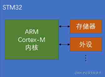
Simply speaking , Namely ARM The company provides cores , then ST The company improves the peripheral memory and peripherals , Make the single chip microcomputer have different functions . Besides , Other SCM companies will also be based on ARM Kernel to add other types of peripherals (Peripherals), Thus forming be based on ARM Kernel but function 、 SCM products of different models .
About ARM The various models of the kernel are shown in the figure below :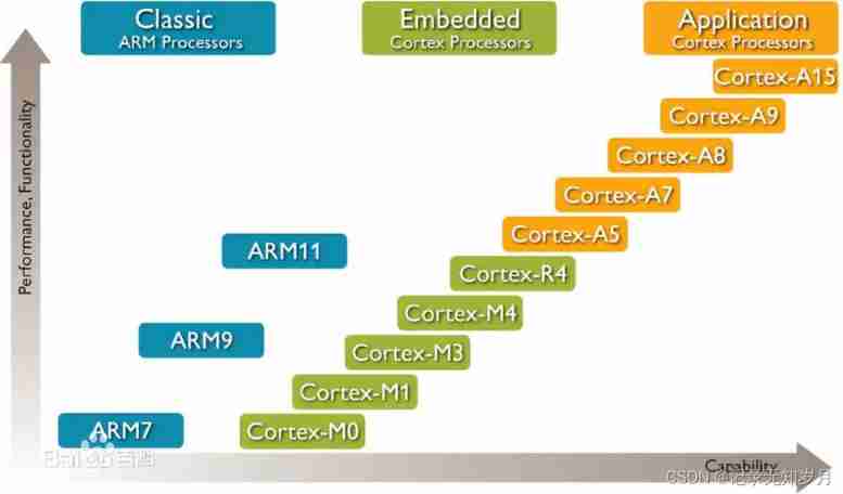
among ,Cortex-M Series is mainly used for embedded and single chip computers , That's what we're used to STM32F103 The kernel of . Other product cores and features are shown in the figure below :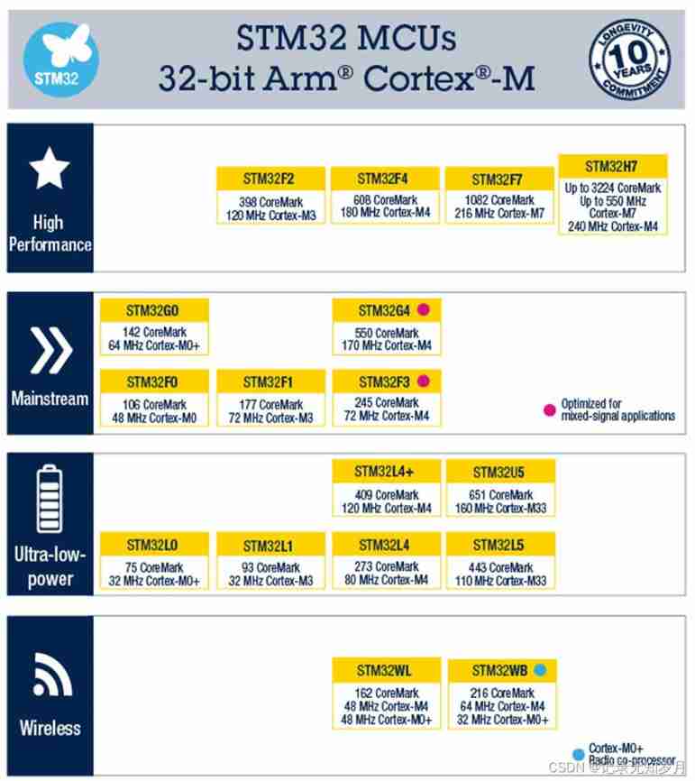
System structure diagram
You can see from the manual , Small 、 in 、 The internal structure of high-capacity products is similar , As shown in the figure below :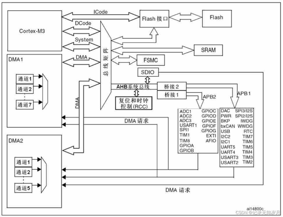
among ,Cortex-M3 For the kernel ,ICode and DCode Instruction bus and data bus related to the kernel , Used to perform Flash Program instructions in ,System For system bus , Used to connect other peripherals .AHB(Advanced High performance Bus) For advanced high-performance bus , Used to connect peripherals with high performance requirements , Like a clock RCC And reset .APB1 and APB2(Advanced Peripheral Bus) For advanced peripheral bus , Used to connect peripherals on the chip , among APB2 The maximum clock is 72MHz,APB1 The maximum clock is 36MHz, because APB1、APB2 The clock and AHB There are some differences , Therefore, a bridge circuit is needed .
Here's the thing to remember , Which peripherals are connected APB1, What are connections APB2, Because it is generally necessary to enable the clock of the corresponding bus before using peripherals , Otherwise, the peripheral cannot run . among ,GPIO And peripheral devices “1 Contestant No ” Mounted on APB2 On , Other peripherals “ Not 1 Contestant No ” and ADC Mount it on APB2 On , Relatively slow .
STM32F103C8T6
The above description is STM32F1 The function and structure of the series integrity , Specific to the smallest system board used and its chip model , Also need to have some understanding .
This video tutorial is based on STM32F103C8T6 The smallest system board of the chip , According to the model selection manual , We can know that the main frequency of this type of chip is 72MHz, The power supply is 2.0~3.6V, General choice 3.3V Power supply .
The circuit schematic diagram of the minimum system board is shown below :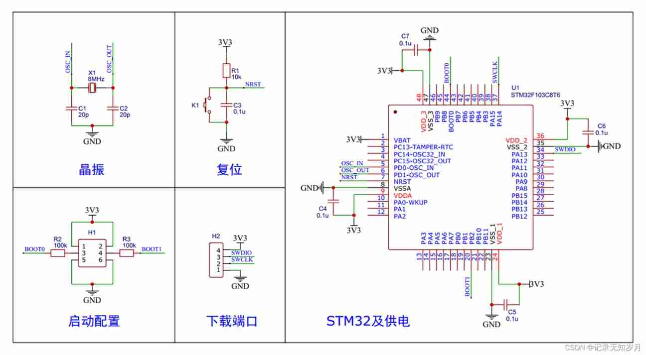
Besides , Attention is also needed STM32 Start configuration of , namely BOOT0 and BOOT1 Configuration of , These two pins determine where the MCU starts to execute the program , The specific settings are shown in the figure below :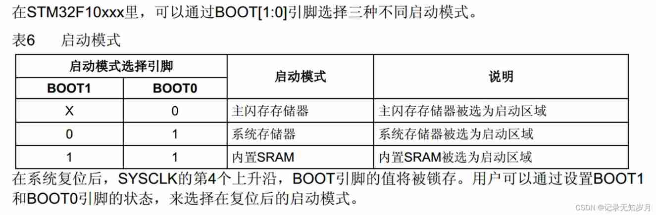
among , In the first mode, the program starts from the main flash memory , Is the mode of normal running program , This mode is generally used ; The second mode is to start from the system memory , That's what we call it BootLoader, Generally used as serial port download .
Besides , According to the notes at the bottom of the table , When the system is reset ,SYSCLK Of the 4 Rising edge ,BOOT The value of the pin will be locked , At this point, you can put BOOT0 The pin configuration is normal IO Mouth .
Standard library development Keil New project
STM32 Development mode , There are three : Register development 、 Standard library development 、HAL Library Development , among , because STM32 All of the registers are 32 position , And a large number , So few people use registers to develop , Most of them use standard libraries or HAL Library to develop . Here we mainly introduce the development method of standard library , So just use Keil that will do .
however , There is a big trouble in the development of standard library , That is, it is troublesome to establish engineering documents , We need to arrive first. ST Download the compressed package of the standard peripheral library on the official website , Then add some files in the project .
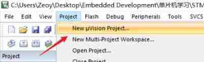
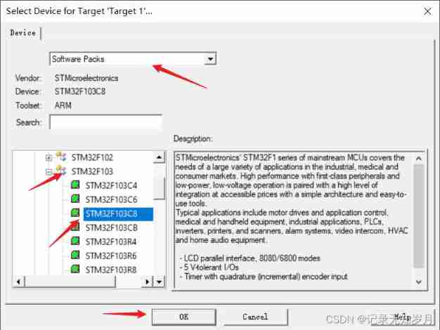
- 1、 Create a project , Select the corresponding device
- 2、 Create several subfolders in the project folder , Convenient for project management :Start、Library、System、User、Peripherals, The name can be any , Easy to understand . And at the same time Keil Create a project with the same name Group.
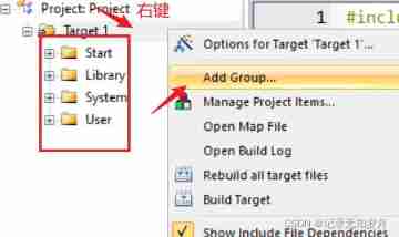
It should be noted that : establish group after , Be sure to add the corresponding folder in the project inclusion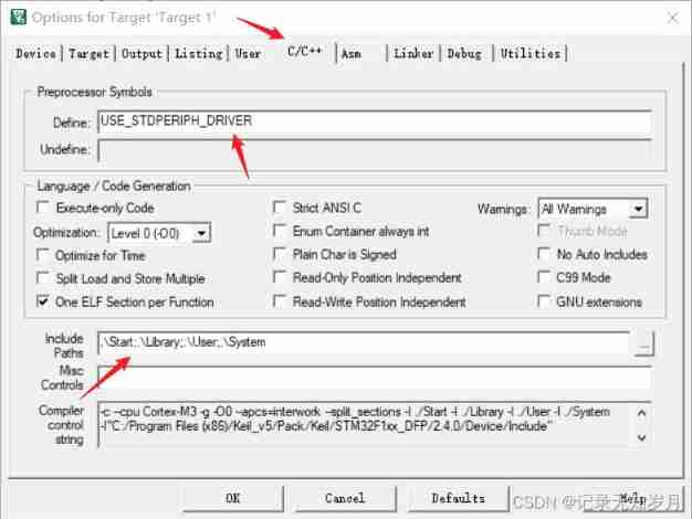
And at the same time define Add the definition of using the standard library :USE_STDPERIPH_DRIVER - 3、 Open a standard library file , stay Keil Add corresponding files in the project . It's complicated here , Refer to the tutorial in the video for details
actually , If you only need some functions , You can only add some official .c and .h file , But to create a “ It's not good to try ” Project engineering template , You can add all source files and header files , It's just that the compilation speed is a little slower .
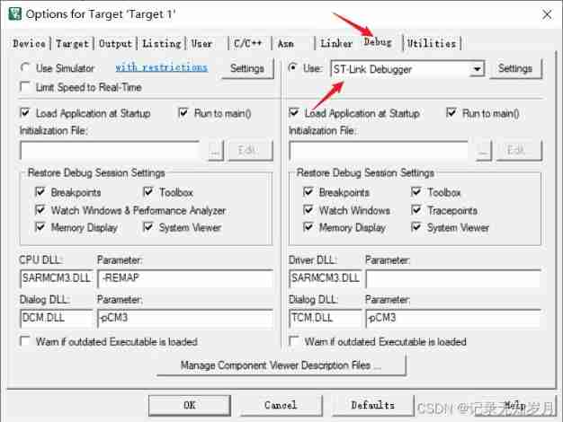
- 4、 Set the debugger according to your actual situation
Step on the pit diary
- 1、 Report errors FCARM - Output Name not specified, please check 'Options for Target - Utilities’
reason : Wrong type selection when adding files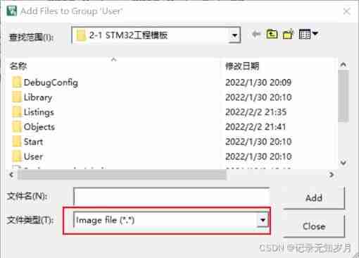
Should be changed to All files. And right click to add the file , You can find the corresponding error of its attribute .
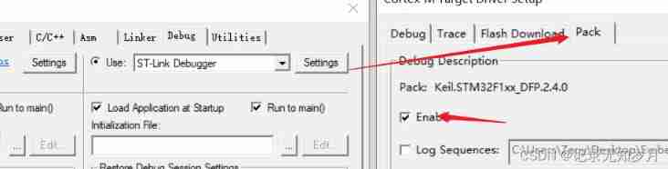
Reference link - 2、 Use ST-Link Download the program to the development board , It is found that the program can only be run by pressing the reset button
solve : Check... In the setting Reset and run outside , You also need to uncheck Enable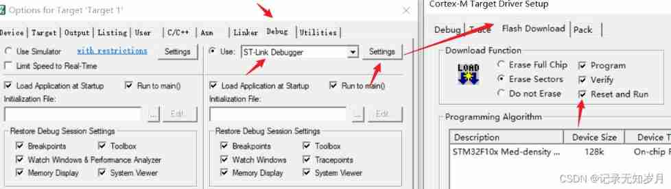
Reference link
GPIO
Additional reference links
summary
STM32 Of GPIO More complicated , But after understanding the principle, it is still very simple to master the basic use . Inside IO The mouth structure is shown in the figure below :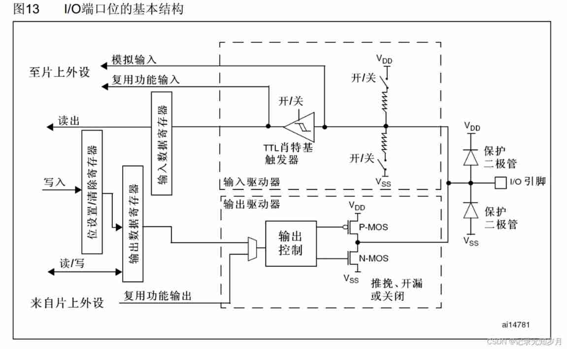
among , It is worth mentioning that , Schottky trigger at input , In essence, it is a Schmidt trigger ( It's a translation error ), It has hysteresis comparison curve , It can make the read signal not affected by fluctuations . Output terminal , Bit settings / The clear register is used to set the output data register , Because the output data register can only be read and written as a whole , And if you need to change a bit , You need to set it in place / Clear register , To write a bit , And other bits do not change the effect .
Precisely because STM32 Of GPIO The internal structure is complex , therefore GPIO A total of... Can be configured 8 Kind of I / O mode , As shown in the following table :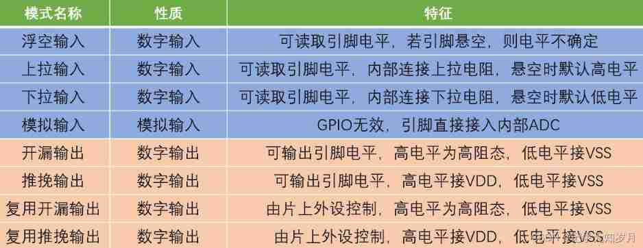
8 The code in the standard library corresponding to each mode is shown in the following figure :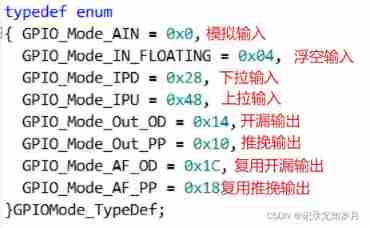
Generally speaking , Use GPIO The steps are as follows :
- Can make the clock ( Can make APB2 Clock on bus )
- initialization GPIO port , Including setting pin (Pin)、 Pattern (Mode)、 Speed (Speed) Equal parameter
- Use the corresponding API Function interface for input and output
among , When initializing the port , Generally, you need to define a GPIO The structure of the body , Then configure the parameters in the structure separately , The reference codes are as follows :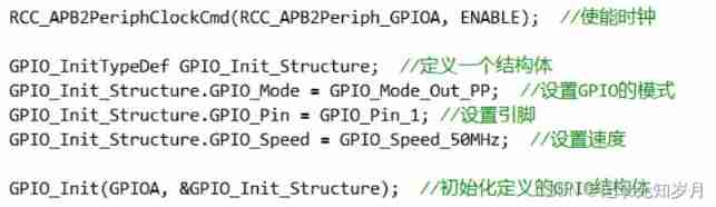
API Function summary
Initialization complete GPIO After the port , Next is the operation input and output , Here we need to use all kinds of API function . How to find these functions ? It's simple , Open the added stm32f10x_gpio.h file , Slide to the bottom , You can see the commonly used API Function .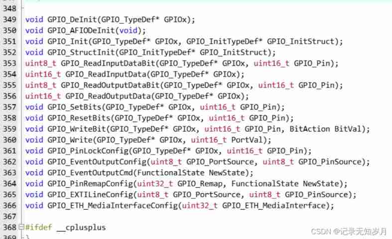
Although the quantity is a little more , But in fact, there are not many commonly used functions . Its function is shown in the figure below :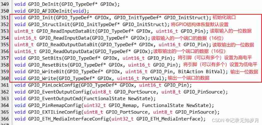
If you need to view the specific definition of the function , You can right-click the function declaration , choice Go To Definition Of xxxxx, If you need to return the function declaration , Right click the defined function , choice Toggle Head.
Attached below is a LED Flashing code :
#include "stm32f10x.h" // Device header
#include "Delay.h"

int main(void)
{

	RCC_APB2PeriphClockCmd(RCC_APB2Periph_GPIOA, ENABLE);

	GPIO_InitTypeDef GPIO_InitStructure;
	GPIO_InitStructure.GPIO_Mode = GPIO_Mode_Out_PP;
	GPIO_InitStructure.GPIO_Pin = GPIO_Pin_0;
	GPIO_InitStructure.GPIO_Speed = GPIO_Speed_50MHz;
	GPIO_Init(GPIOA, &GPIO_InitStructure);

	while (1)
	{

		GPIO_ResetBits(GPIOA, GPIO_Pin_0);
		Delay_ms(500);
		GPIO_SetBits(GPIOA, GPIO_Pin_0);
		Delay_ms(500);

		GPIO_WriteBit(GPIOA, GPIO_Pin_0, Bit_RESET);
		Delay_ms(500);
		GPIO_WriteBit(GPIOA, GPIO_Pin_0, Bit_SET);
		Delay_ms(500);

		GPIO_WriteBit(GPIOA, GPIO_Pin_0, (BitAction)0);
		Delay_ms(500);
		GPIO_WriteBit(GPIOA, GPIO_Pin_0, (BitAction)1);
		Delay_ms(500);
	}
}
CubeMX Study the tutorial
https://zhuanlan.zhihu.com/STM32CubeMX
https://www.waveshare.net/study/article-629-1.html
边栏推荐
- [IELTS reading] Wang Xiwei reads P4 (matching2 paragraph information matching question [difficult])
- Detailed explanation of openharmony resource management
- 巩固表达式C# 案例简单变量运算
- How to avoid arc generation—— Aafd fault arc detector solves the problem for you
- Go pit - no required module provides Package: go. Mod file not found in current directory or any parent
- TS quick start - functions
- Using fast parsing intranet penetration to realize zero cost self built website
- TS快速入门-函数
- What did I pay for it transfer to testing post from confusion to firmness?
- Is it safe to open an account in the College of Finance and economics? How to open an account?
猜你喜欢

How many triangles are there in the golden K-line diagram?
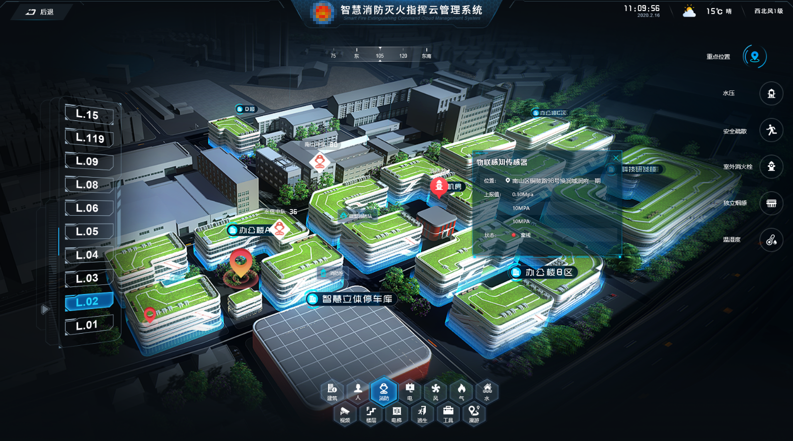
基于三维gis平台的消防系统运用
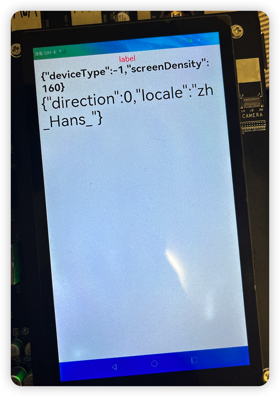
OpenHarmony资源管理详解
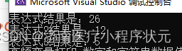
Consolidated expression C case simple variable operation
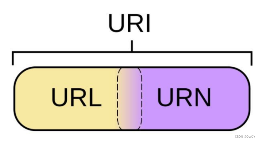
URL和URI

他做国外LEAD,用了一年时间,把所有房贷都还清了
It's too convenient. You can complete the code release and approval by nailing it!

Skills in analyzing the trend chart of London Silver

Data on the number of functional divisions of national wetland parks in Qinghai Province, data on the distribution of wetlands and marshes across the country, and natural reserves in provinces, cities
Using fast parsing intranet penetration to realize zero cost self built website
随机推荐
lambda表达式
Enterprise application business scenarios, function addition and modification of C source code
Summary of week 22-07-02
(script) one click deployment of any version of redis - the way to build a dream
2022.07.03 (lc_6111_counts the number of ways to place houses)
Fs8b711s14 electric wine bottle opener MCU IC scheme development special integrated IC
[path planning] RRT adds dynamic model for trajectory planning
挖财学院开户安全的吗?开户怎么开?
Fast analysis -- easy to use intranet security software
uniapp上传头像
GDB common commands
Complete knapsack problem (template)
Introduction to ACM combination counting
IELTS examination process, what to pay attention to and how to review?
【路径规划】RRT增加动力模型进行轨迹规划
Data on the number of functional divisions of national wetland parks in Qinghai Province, data on the distribution of wetlands and marshes across the country, and natural reserves in provinces, cities
同事的接口文档我每次看着就头大,毛病多多。。。
如何避免电弧产生?—— AAFD故障电弧探测器为您解决
Learning of basic amplification circuit
Basic points of the game setup of the points mall