当前位置:网站首页>【nRF24L01 connects with Arduino to realize wireless communication】
【nRF24L01 connects with Arduino to realize wireless communication】
2022-08-02 04:33:00 【WENJIE Technology】
nRF24L01 与 Arduino Connect wireless communication
前言
在本教程中,You will use two examples to understand nRF24L01 Arduino 接口.在第一个示例中,我们将发送“Hello world”And a command to blink to connect to another Arduino 的 LED.在第二个示例中,We'll have a two-way control,And from the first Arduino Send commands to the second Arduino 上闪烁 LED,Then we will from the second Arduino Send the command to the first Arduino 上闪烁 LED.
nRF24L01 模块
nFR24L01 Is a transceiver module,This means that it can send and receive data.These modules are very cheap,体积更小,There are many specifications.Some of these module specifications are as follows:
In the process of transmission power consumption in12mA左右,比LED还要小.
它可以以 250Kbps 到 2 Mbps The baud rate of running.
If used in open space with the antenna,The range of 100 米.
它可以同时发送和接收数据.
Each module maximum and 6 Other modules communication.
它使用 2.4 GHz 频段.
它可以以 1 MB The transmission rate of sending 1 到 25 Bytes of the original data.
它有 125 个不同的频道.
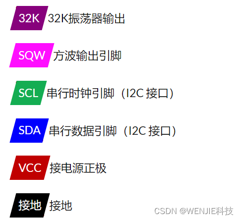
nRF24L01 模块通过 SPI 通信与 Arduino 协同工作.Module pin is as follows:
The working voltage of the module as 1.9 至 3.6V,But other pins can withstand 5V,This means that the other pin can be connected directly to the Arduino.
MOSI、MISO 和 SCK 是 SPI 引脚,The need to connect to the Arduino 的 SPI 引脚.不同的 Arduino 有不同的 SPI 引脚.
CSN 和 CE Model is used to set the module to activities and in command mode and delivery mode switch between.These can be connected to Arduino 的任何数字引脚.
IRQ Pin is interrupt pin,You don't have to connect it.
示例 1 - nRF24L01 Arduino 接口
在 nRF24L01 arduino Interface in the first example,We will simply be data from a Arduino 发送到另一个 Arduino.When we press the connection to the first Arduino 的按钮时,Connected to the second Arduino 的 LED 会亮起.
The first example of the circuit diagram as shown below,连接如下所示.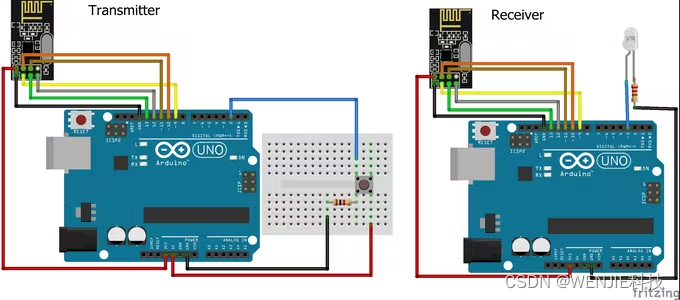 Transmitter code:
#include <SPI.h>
#include <nRF24L01.h>
#include <RF24.h>
RF24 radio(9, 10); // CE, CSN
const byte address[6] = "00001"; //地址
int button_pin = 2;
boolean button_state = 0;
void setup() {

pinMode(button_pin, INPUT);
radio.begin();
radio.openWritingPipe(address);
radio.setPALevel(RF24_PA_MIN);
radio.stopListening();
}
void loop()
{

button_state = digitalRead(button_pin);
if(button_state == HIGH)
{

const char text[] = "Your Button State is HIGH";
radio.write(&text, sizeof(text));     //发送数据
}
else
{

const char text[] = "Your Button State is LOW";
radio.write(&text, sizeof(text));    //发送数据
}
radio.write(&button_state, sizeof(button_state));
//发送数据
delay(1000);
}
接收方代码:
#include <SPI.h>
#include <nRF24L01.h>
#include <RF24.h>
RF24 radio(9, 10); // CE, CSN
const byte address[6] = "00001";//地址保持一致
boolean button_state = 0;
int led_pin = 3;
void setup() {

pinMode(6, OUTPUT);
Serial.begin(9600);
radio.begin();
radio.openReadingPipe(0, address);
radio.setPALevel(RF24_PA_MIN);
radio.startListening();
}
void loop()
{

if (radio.available())          //等待接收数据
{

char text[32] = "";                 //保存数据
radio.read(&text, sizeof(text));
radio.read(&button_state, sizeof(button_state));
if(button_state == HIGH)
{

digitalWrite(6, HIGH);
Serial.println(text);
}
else
{

digitalWrite(6, LOW);
Serial.println(text);}
}
delay(5);
}
示例 2 - nRF24L01 Arduino 接口
在 nRF24L01 Arduino In the second example interface,We'll have a two-way communication.首先,We will be from the first Arduino Send commands to light is connected to the second Arduino 的 LED,Then we will from the second Arduino Send commands to light is connected to the first Arduino 的 LED.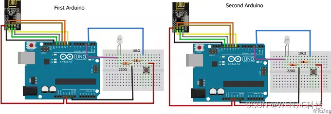 第一个 Arduino 的代码:
#include <SPI.h>
#include <nRF24L01.h>
#include <RF24.h>
RF24 radio(9, 10); // CE, CSN
const byte addresses [][6] = {
    "00001", "00002"};
 //发送地址和接收地址
int button_pin = 2;
int led_pin = 3;
boolean button_state = 0;
boolean button_state1 = 0;
void setup() {

  pinMode(button_pin, INPUT);
  pinMode(led_pin, OUTPUT);
  radio.begin();
  radio.openWritingPipe(addresses[1]);
  radio.openReadingPipe(1, addresses[0]);
  radio.setPALevel(RF24_PA_MIN);
}
void loop()
{

  delay(5);
  radio.stopListening();                                 //Set to the sender
  button_state = digitalRead(button_pin);
  radio.write(&button_state, sizeof(button_state));  //发送数据
  delay(5);

  radio.startListening();                            //Set to the receiving end
  while(!radio.available());                         //等待接收数据
  radio.read(&button_state1, sizeof(button_state1)); //读取数据
  if (button_state1 == HIGH)
  {

    digitalWrite(led_pin, HIGH);
  }
  else
  {

    digitalWrite(led_pin, LOW);
  }
}
第二个 Arduino 的代码:
#include <SPI.h>
#include <nRF24L01.h>
#include <RF24.h>
RF24 radio(9, 10); // CE, CSN
const byte addresses [][6] = {
    "00001", "00002"};
 //发送地址和接收地址
int button_pin = 2;
boolean button_state = 0;
boolean button_state1 = 0;
int led_pin = 3;
void setup() {

  pinMode(led_pin, OUTPUT);
  Serial.begin(9600);
  radio.begin();
  radio.openWritingPipe(addresses[0]);
  radio.openReadingPipe(1, addresses[1]);
  radio.setPALevel(RF24_PA_MIN);
}
void loop()
{

  delay(5);
  radio.startListening();
  //Set to the receiving end
  if (radio.available())
  //等待接收数据
  {

    radio.read(&button_state, sizeof(button_state));
    if(button_state == HIGH)
  {

     digitalWrite(led_pin, HIGH);
  }
  else
  {

     digitalWrite(led_pin, LOW);
  }
  delay(5);

  radio.stopListening();
   //Set to the sender
  button_state1 = digitalRead(button_pin);
  radio.write(&button_state1, sizeof(button_state1));         //发送数据
  }
}
The source code and libraries
Source code and library files have been uploaded to the personal home page
边栏推荐
- 从Attention到Self-Attention和Multi-Head Attention
- GM8284DD,GM8285C,GM8913,GM8914,GM8905C,GM8906C,国腾振芯LVDS类芯片
- openmv学习 2022.5.9
- Arduino点亮数码管
- 工业边缘网关究竟强大在哪里?
- AD PCB导出Gerber文件(非常详细的步骤)
- [DS3231 RTC real-time clock module and Arduino interface to build a digital clock]
- AD8361检波器
- LT9211芯片资料分享
- 【Popular Science Post】UART Interface Communication Protocol
猜你喜欢


随机推荐
3D建模作品
MC1496乘法器
Out of memory error on GPU 0. Cannot allocate xxxGB memory on GPU 0, available memory is only xxx
基于树莓派的智能箱包开发环境搭建
Arduino lights up nixie tubes
Typora使用
VCA821可变增益放大器
【Arduino 连接DHT11 湿度和温度传感器】
openmv学习 2022.5.9
分布式消息队列平滑迁移技术实战
【科普贴】I2C通讯协议详解——偏软件分析和逻辑分析仪实例分析
出差电子流应用实战
Arduino点亮数码管
Arduino D1----Mlx90614红外温度传感器接线和安装包
【TCS3200 颜色传感器与 Arduino 实现颜色识别】
PCB设计思路
远程调试PLC,到底如何操作?
[Arduino connected to GP2Y1014AU0F dust sensor]
uniCloud使用
umi3 权限路由PrivateRoute未执行