当前位置:网站首页>[Arduino connected to GP2Y1014AU0F dust sensor]
[Arduino connected to GP2Y1014AU0F dust sensor]
2022-08-02 04:32:00 【WENJIE Technology】
Arduino 连接GP2Y1014AU0F 灰尘传感器
GP2Y1014AU0F Dust sensor pins
GP2Y1014AU0FDust sensor module has6个引脚;它们是 V-LED、LED-GND、LED、S-GND、VOUT 和 VCC.The output of this sensor is analog,We need to connect this pin to the microcontroller's ADC to measure in air PM.GP2Y1014AU0F The pins of the dust sensor are shown in the picture below: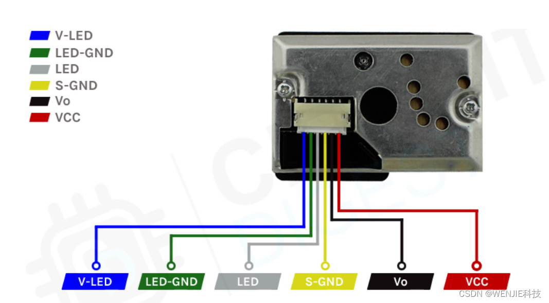 V-LED==》这是 LED 的 VCC 引脚.使用 150Ω A current limiting resistor connects this pin to Arduino 的 5V 引脚.
LED-GND==》这是 LED 的接地引脚.Connect this pin to Arduino 的接地引脚.
LED==》This pin can be used for switching LED 开/关.将其连接到 Arduino of any digital pins.
S-GND==》is the ground pin of the pulse dust sensor module,它应该连接到 Arduino 的接地引脚.
Vo==》This is the output of the dust sensor module,您可以将其连接到 Arduino of any analog pins.
VCC==》The power pins of the dust sensor module are connected to Arduino 的 5V 或 3.3V 引脚.
GP2Y1014AU0F How the dust sensor module works?
GP2Y1014AU0F The working principle of the dust sensor is simple and easy to understand.inside the sensor,有三个主要部分,They are light emitting diodes(光源)、光电二极管(检测器)and a pair of lenses.inside the sensor LED and photodiodes are placed in such a way that the two optical axes pass through the detection area in the sensor.When dust or smoke enters the detection area of the sensor,Light inside the sensor can be reflected by dust or smoke,So the current generated by the photodiode varies according to the amount of light detected.Convert and amplify the current value to a voltage value by using an appropriate circuit,We can get the desired output from the sensor. 要使用传感器,You only need two of all six pins.第一个触发 LED,The second outputs an analog signal from the sensor.LEDThe pulse drive requires the resistors mentioned aboveR1=150Ω和电容C1=220uF.There are no resistors and capacitors,Module does not work.To get the required data from the sensor,您需要使用 10ms 脉冲触发 LED,where the pulse width should not exceed 0.32ms.And as suggested by the datasheet,我们应该在 0.28ms 之后,在向 LED The signal is sampled after the trigger pulse is provided.
GP2Y1014AU0F Dust sensor module
The structure of the sensor makes it difficult to label all the major components of the sensor in one image,这就是我们将 GP2Y1014AU0F The reason why the part marking of the sensor is split in two.
在上图中,When the front cover is open,You can see inside the sensor module PCB.PCB There is a main processor for processing data from the photodiodes IC、A potentiometer and a driver LED 的晶体管.除此之外,We also have one for VCC、ground and output data JST 连接器.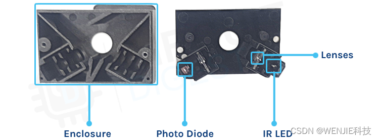 The image above shows what it looks like when the sensor is removed.在左侧,We have the housing for the sensor module,在右侧,我们有 PCB 的背面.在 PCB 上,您可以看到 LED and connected photodiode,在 LED and the front of the photodiode,You can see the lens that focuses the beam.
Frequently Asked Questions about Dust Sensor Modules
Dust sensor and PM2.5 What is the difference between sensors?
PM2.5 refers to the diameter of 2.5 micron or smaller particles.The sensor uses laser light scattering to irradiate suspended particles in the air,The scattered light is then collected,A plot of scattered light versus time is obtained.Dust sensors use photodiodes to detect dust.
What is the difference between an optical dust sensor and a laser dust sensor?
A laser dust sensor is a sensor that uses laser technology to measure dust concentration.it is driven by a fan、激光二极管、Receiver and measurement circuit composition.But in the optical dust sensor,Infrared LEDs and phototransistors are arranged diagonally,This enables it to detect reflected light from dust in the air.
How to test a dust sensor?
To test the dust sensor,You'll need to add the appropriate pulse driver circuit recommended by the datasheet for the specific device you're using,Then you need to use a microprocessor or microcontroller to sample and calculate the output data.
Arduino GP2Y1014AU0FDust sensor circuit connection diagram
现在我们已经完全了解了 GP2Y1014AU0F How the dust sensor works,我们可以将所有必需的电线连接到 Arduino,Then write the code to get the data from the sensor module.GP2Y1014AU0FDust sensor withArduino的连接图如下所示.
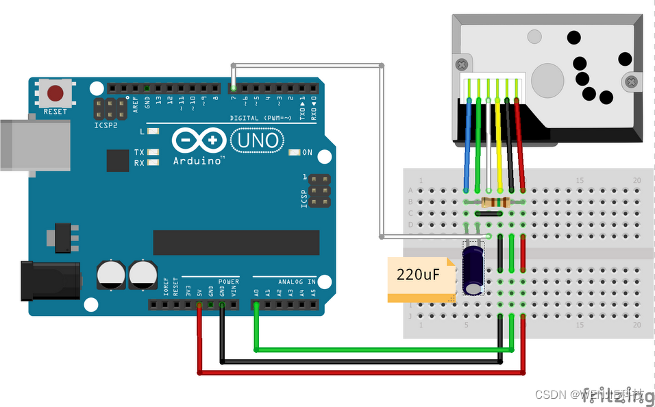 将 GP2Y1014AU0F Dust sensor with Arduino It's very simple to connect.从上面的讨论中我们知道,This sensor gives data by the voltage change on the output pin.所以我们需要使用 Arduino 的 ADC Transform and compute data into recognizable values.We also need to place the sensors LED The enable pin is connected to Arduino 的 GPIO 引脚之一,它是连接到 Arduino 的 D7 的白线.最后,我们需要一个 150R resistors and a 220uF 的电容.Resistors and capacitors form one RC 定时器电路,In our case it is a pulse driver circuit,It is absolutely necessary for the stable operation of the device,And these values are recommended in the datasheet.
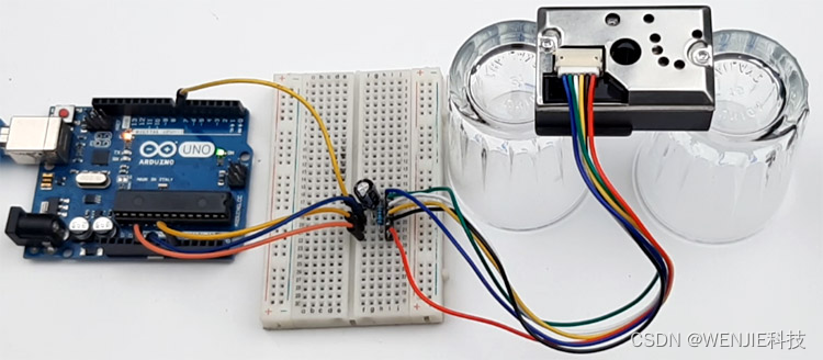
Arduino 代码
处理来自 GP2Y1014AU0F 传感器数据的 Arduino 代码非常简单易懂.We just need to convert the analog voltage given by the sensor to digital data to get our result.
We start our code by defining the analog input pins of the device,We also define a for control LED 的数字引脚.接下来,我们定义了三个变量,They will hold the necessary time value required to calculate the dust measured by the sensor.接下来,We have three floating point variables to hold the results generated by the sensor.
#define measurePin = 0; //Connect dust sensor to Arduino A0 pin
#define ledPower = 7; //Connect 3 led driver pins of dust sensor to Arduino D2
int samplingTime = 280; // time required to sample signal coming out of the sensor
int deltaTime = 40; //
int sleepTime = 9680;
float voMeasured = 0;
float calcVoltage = 0;
float dustDensity = 0;
接下来,我们有我们的设置功能.在 setup 函数中,We enable serial port for debugging,并将ledpin作为输出.
void setup(){

  Serial.begin(9600);
  pinMode(ledPower,OUTPUT);
}
接下来,We have our loop function;in the loop function,We begin the measurement process recommended by the datasheet.The entire measurement process takes approx 10 毫秒,But the sampling period is 0.28 毫秒.首先,我们将打开 LED 的 LED pin is set low,然后使用delayMicroseconds()The function to generate the datasheet is recommended 280 uS 或 0.28mS 延迟.Then we take a sample and add another 40uS 的延迟,This will ensure that the pulse width remains in 0.32ms 或 320us 并且我们在 9680uS sleep for the rest of the time.
  digitalWrite(ledPower,LOW); // power on the LED
   (samplingTime);
  voMeasured = analogRead(measurePin); // read the dust value
  delayMicroseconds(deltaTime);
  digitalWrite(ledPower,HIGH); // turn the LED off
  delayMicroseconds(sleepTime);
接下来,我们根据 ADC value to calculate the voltage value.请确保您的 Arduino 由正确的 +5V 电源供电,如果是这样,You will get wrong results.
calcVoltage = voMeasured * (5.0 / 1024.0);
最后,我们使用 Chris Nafis The provided linear equation calculates the amount of suspended dust particles;单位为ug/m3,and print the result in the serial monitor window.
dustDensity = 170 * calcVoltage - 0.1;
Serial.println(dustDensity);
delay(1000);
GP2Y1014AU0F The working of the dust sensor module
下面的 gif 显示了使用 Arduino 的 GP2Y1014AU0F The hardware circuit of the dust sensor.在左侧,我们将 Arduino 与 GP2Y1014AU0F 传感器连接到 Arduino 的 ADC 引脚,在右侧,We have the serial monitor window,如您所见,When we turn the incense off to the sensor,It detects smoke,The value of the sensor gradually increases.

边栏推荐
猜你喜欢


随机推荐
synchronized锁原理详解
关于我的项目-微信公众号~
【树莓派入门(2)树莓派的远程控制】
使用批处理脚本修改hosts文件
Flutter入门之网络请求篇
【萌新解题】斐波那契数列
浅谈性能优化:APP的启动流程分析与优化
【Arduino连接时钟模块在LCD1602上显示时间】
Temporal action localization in untrimmed videos via Multi-stage CNNs SCNN论文阅读笔记
树莓派4B打开文件管理时出现闪退
分布式消息队列平滑迁移技术实战
深度学习理论:model.fit 函数参数详解
将ORCAD原理图导入allegro中进行PCB设计
whistle 手机调试代理工具
Nest 的实现原理?理解了 reflect metadata 就懂了
zsh: command not found: xxx 解决方法
保证接口数据安全的10种方案
umi3 权限路由PrivateRoute未执行
基于阿里云OSS+PicGo的个人图床搭建
Jetpack中各个组件简介