当前位置:网站首页>【Popular Science Post】UART Interface Communication Protocol
【Popular Science Post】UART Interface Communication Protocol
2022-08-02 04:32:00 【Tiantian's little tiger】
I. Introduction to the Agreement
UART is a Universal Asynchronous Receiver/Transmitter, commonly referred to as a serial port in the industry.UART is a full-duplex communication mechanism, that is, sending and receiving are two relatively independent lines, and sending and receiving can be performed at the same time.
1, baud rate
The rate at which information is transmitted in a communication channel is called the baud rate, which is usually the number of bits transmitted per second, expressed in bit/s.The baud rates from low to high are: 2400, 4800, 9600, 115200, etc. You can also set them yourself, but the usual serial port tools usually only have these options.To facilitate debugging.Rarely use their own private provisions.
The reason why 2400, 4800, 9600 and 115200 are usually used: The baud rate unit is bit/s, which is binary bits/second.Because a byte is 8 bits, and a byte can usually express an ASCII code, such as an English letter, so: a channel with a baud rate of 9600 can theoretically transmit 9600/8 English letters per second., which is 1200 bytes.
UART uses a single data line for transmission and has no reference clock, so the transceiver must use the same baud rate to communicate and parse the data, and the clock error at both ends should not be too large, otherwise garbled characters will appear.
2. Communication data format

The serial port is high when the serial port is idle.When high becomes low, it is considered as the start bit.
The serial port transmits the low bits first, and then transmits the high bits, which is different from I2C, SPI and other signal transmissions that transmit the high bits first
The time width of the bit bit in the serial port transmission byte=1/baud rate
Second, hardware design
1, when the transmitter and receiver have the same level fields

2. Inconsistency between the transmitter and receiver level fields
1) Use resistor divider method
As shown in the figure above, the left side is 3.3V system, and the right side is 5V system. When the 5V level client sends data to the left side, the voltage is divided by two resistors, and the voltage of the left side receiving terminal is about 5V*2K/(1K+2K)≈3.3V, thus achieving level matching.
The TX of the left 3.3V system is usually directly connected to the RX of the right 5V system, or a 2K resistor is added between the two, and then a 1K pull-up is added to the 5V system side, so as to make the 5V side RX level meet the requirementslevel requirements.
2) Level conversion chip scheme, there are many products in this category, and I will not repeat them here
3) Transistor conversion scheme
The circuit in the above picture uses two NPN transistors, which can convert the input signal 3.3V level to 5V output level, and the signals remain synchronized.Circuit description: When TX is low, Q3 is off, Q4 is on, and RX is grounded low; when TX is high, Q3 is on, Q4 is off, and RX is pulled up to 5V.In this way, the two are synchronized high and low, and the level is converted.
The advantages of this circuit are low cost, strong driving ability, and relatively mature and extensive circuit applications.The disadvantage is that there is a delay in converting the waveform through the triode, so the rate cannot be too fast (the baud rate does not exceed 230400).When multiplexing, there are more materials, which requires a larger layout space.
边栏推荐
猜你喜欢


随机推荐
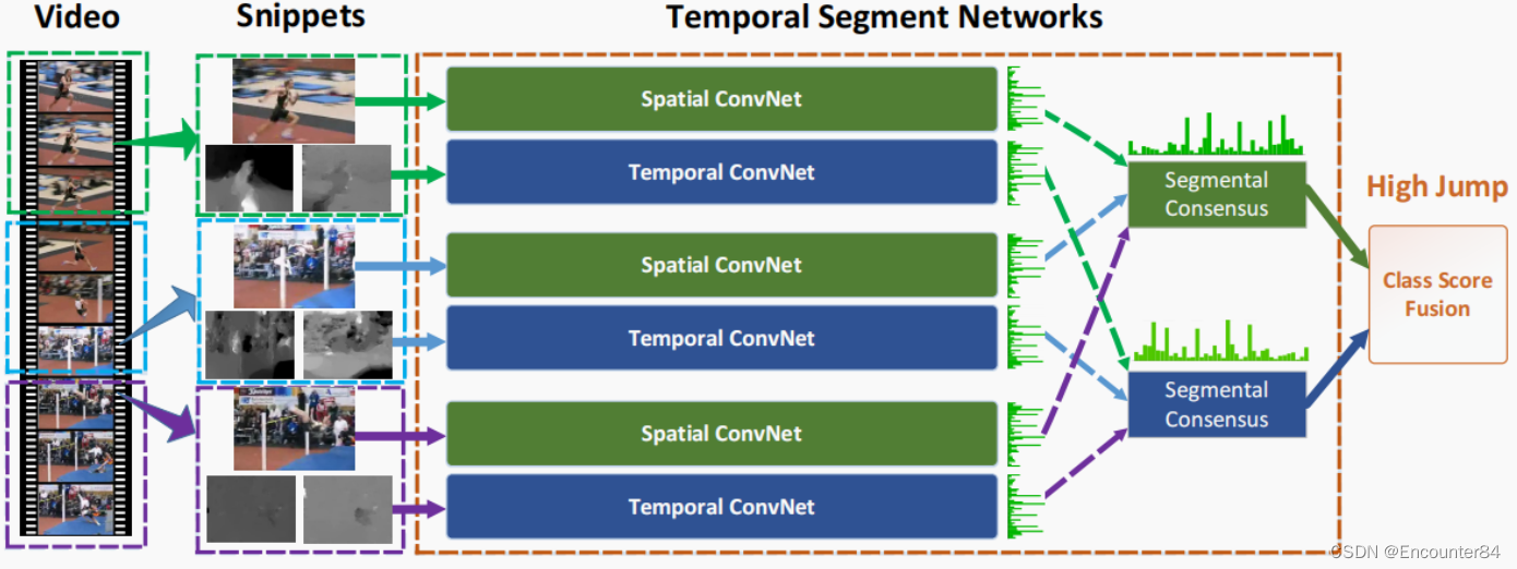
Temporal Segment Networks:Towards Good Practices for Deep TSN论文精读笔记
无源域适应(SFDA)方向的领域探究和论文复现(第一部分)
Vision Transformer(ViT)论文精读和Pytorch实现代码解析
cmd控制台窗体大小设置
Visual Studio2022创建setup项目
synchronized锁原理详解
Scala,Spark依赖jar包冲突解决方法
蓝桥杯:国二选手经验贴 附蓝桥杯历年真题
【Arduino 连接DHT11 湿度和温度传感器】
[DS3231 RTC real-time clock module and Arduino interface to build a digital clock]
【NTC 热敏电阻与 Arduino 读取温度】
Spark MLlib特征处理 之 StringIndexer、IndexToString使用说明以及源码剖析
【科普贴】I2C通讯协议详解——偏软件分析和逻辑分析仪实例分析
【DS3231 RTC实时时钟模块与Arduino接口构建数字时钟】
RecyclerView使用和原理解析
PCB设计思路
工业边缘网关究竟强大在哪里?
C#从入门到精通
ArrayList LinkList效率对比
ffmpeg 有声视频合成背景音乐(合成多声音/合成多音轨)