当前位置:网站首页>Virtual lab basic experiment tutorial -7 Polarization (2)
Virtual lab basic experiment tutorial -7 Polarization (2)
2022-07-02 17:41:00 【Chengyuan】
List of articles
Preface
This is the eighth collective work of Dachuang team , It is still a basic experiment for physical optics – The phenomenon of polarization has been explored and tried . This chapter introduces the rest of the experiment ( Some experiments may not be very convenient to do ).
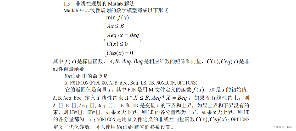
One 、 Introduction to wave plates and birefringent crystals
1、 Examples of Jones matrix for typical devices :
The meaning of Jones matrix
[ A 2 B 2 ] = [ g 11 g 12 a 21 a 22 ] [ A 1 B 1 ] \begin{bmatrix} {A_{2}}\\ {B_{2}} \end{bmatrix}=\begin{bmatrix} {g_{11}}&{g_{12}}\\ {a_{21}}&{a_{22}} \end{bmatrix}\begin{bmatrix} {A_{1}}\\ {B_{1}} \end{bmatrix} [A2B2]=[g11a21g12a22][A1B1]
The component form is
{ A 2 = g 11 A 1 + g 12 B 1 B 2 = g 21 A 1 + g 22 B 1 g 11 、 g 12 、 g 21 、 g 22 One like by complex often Count \begin{cases} A_2=g_{11}A_1+g_{12}B_1\\ B_2=g_{21}A_1+g_{22}B_1 \end{cases} \ \ g_{11}、g_{12}、g_{21}、g_{22} Generally, it is a complex constant { A2=g11A1+g12B1B2=g21A1+g22B1 g11、g12、g21、g22 One like by complex often Count
Express : Polarizer devices play the role of linear transformation in polarization state conversion .
The two components of the new polarization state are the linear combination of the two components of the original polarization state
(1). Linear polarizer :
On the light transmission axis and x The included angle of the shaft is classified and discussed
1.1 Light transmission axis x Axis
[ 1 0 0 0 ] \begin{bmatrix} {1}&{0}\\ {0}&{0} \end{bmatrix} [1000]
We can analyze from Jones matrix that only x The light of the axis can pass
1.2 Light transmission axis y Axis
[ 0 0 0 1 ] \begin{bmatrix} {0}&{0}\\ {0}&{1} \end{bmatrix} [0001]
inductive : The light transmission shaft is formed with the shaft θ \theta θ Corner time
G = [ c o s 2 θ 1 2 s i n 2 θ 1 2 s i n 2 θ s i n 2 θ ] G=\begin{bmatrix} {cos^2\theta}&{\frac{1}{2}sin2\theta}\\ {\frac{1}{2}sin2\theta}&{sin^2\theta} \end{bmatrix} G=[cos2θ21sin2θ21sin2θsin2θ]
1.3 1 4 \frac{1}{4} 41 wave plate
Fast shaft edge x Axis or y Axis ( Add π \pi π And subtraction π \pi π Are added with a minus sign )
[ 1 0 0 − 1 ] \begin{bmatrix} {1}&{0}\\ {0}&{-1} \end{bmatrix} [100−1]
That is, the slow axis lags behind the fast axis π \pi π
1.4 Fast axis and x Included angle of shaft 45°
[ 0 1 1 0 ] \begin{bmatrix} {0}&{1}\\ {1}&{0} \end{bmatrix} [0110]
The following is the Jones matrix of a typical polarizer 
(2). wave plate
Phase retarder : The light that makes the two vibration directions perpendicular to each other produces a phase retarder
2.1 λ 2 \frac{\lambda}{2} 2λ wave plate
Linearly polarized light is incident on a half wave plate , The outgoing light is still linearly polarized , If the linearly polarized light of the incident light and the fast axis ( Slow axis ) α \alpha α Angle , Then the vibration direction of the emitted light is towards the fast axis ( Slow axis ) turn 2 α 2\alpha 2α
round ( The ellipse ) Polarized light enters the half wave plate , The outgoing light is still round ( The ellipse ) Polarized light , But the rotation direction is opposite .
2.2 λ 4 \frac{\lambda}{4} 4λ wave plate
When linearly polarized light is incident
If the vibration direction of the polarized light of the incoming ray is consistent with the direction of the fast axis or the slow axis , Then the emitted light is still linearly polarized .
If the angle between the vibration direction of the polarized light of the incoming ray and the fast and slow axis 45°,( At this time, the amplitude of decomposition along the fast and slow axis is the same , And the phase difference is 90°), The outgoing light is circularly polarized light .
If the vibration direction of the polarized light of the incoming ray forms another angle with the included angle between the fast and slow axis , Then the outgoing light is elliptically polarized .
When circularly polarized light is incident , Change to linearly polarized light .
When elliptically polarized light is incident :
If the long axis and short axis directions of the elliptically polarized light are consistent with the fast and slow axis directions of the wave plate ( Only positive ellipses exist 90° Phase difference of , Just can use $\frac{\lambda}{4} Wave plate 90° Phase lag ), The outgoing light is linearly polarized light .
In case of other directions , The outgoing light is still elliptically polarized .
2、 Birefringent crystal
Definition :
When a beam of light is projected onto the crystal interface , Generally, two refracted beams will be generated , This phenomenon is called birefringence . Due to the anisotropy of crystal materials , The angle between the two refracted rays is related to the propagation direction and polarization state of the light wave . A crystal that produces birefringence is called a birefringent crystal . The function of birefringent crystal is similar to that of polarizer with two mutually perpendicular vibration transmission directions .
classification :
Birefringent crystals are divided into uniaxial crystals and biaxial crystals .
Uniaxial crystal :
Uniaxial crystal refers to a crystal with only one optical axis . When light passes through some crystals , It will be refracted into two beams . One of them conforms to the general law of refraction and is called ordinary light ( abbreviation o light ), Refractive index in n o n_o no Express ; The refractive index of the other beam changes with the incident angle , It is called extraordinary light ( abbreviation e light ), Refractive index in n e n_e ne Express .
Generally, there are always one or two directions in a crystal , When light travels in this direction in the crystal , No birefringence , This direction is called the optical axis direction of the crystal .
Those with only one optical axis are called uniaxial crystals , A crystal with two optical axes is called a biaxial crystal . The plane determined by the optical axis and light of the crystal is called the main section of the crystal . It was found that ,o Light and e Light is linearly polarized , But their light vectors ( Generally refers to the electric field vector E) The direction of vibration is different ,o The light vector vibration direction of light is perpendicular to the main section of the crystal ,e The light vector vibration direction of light is parallel to the main section of the crystal . When the optical axis of the crystal is in the incident plane ,o Light and e The main sections of light coincide , The vibration directions of electro-optic vectors are perpendicular to each other .
Biaxial crystal :
Like mica , Sapphire and other crystals have two optical axis directions , They are called biaxial crystals . The three main dielectric coefficients of biaxial crystals are not equal , namely ϵ 1 ≠ ϵ 2 ≠ ϵ 3 \epsilon_1\neq\epsilon_2\neq\epsilon_3 ϵ1=ϵ2=ϵ3, thus n 1 ≠ n 2 ≠ n 3 n_1 \neq n_2 \neq n_3 n1=n2=n3. The plane formed by these two optical axes is called the optical axis plane .
Two 、VirtualLab Simulation
1、 Phase shift element
First , Build the optical path diagram of polarization phase shift . Add a plane wave .
double-click , Set the plane wave , The initial angle is set to 45°.
next , Add a phase shift device Phase Shift.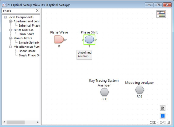
Double click to set it , Set to π \pi π/4 It is about 0.7854rad.
here ,Use Cubic Interpolation Options can be selected or not , It does not affect the phase shift phenomenon of this simulation .( We talked about that in the last post , Use 7.6.1.18 In version, this is checked by default )
next , Add two detectors Raw Data Detector.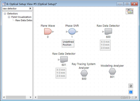
As shown in the figure below , Connect devices , The light path map is completed .
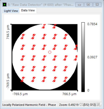
Click on the run , Different from the last experiment , This simulation experiment studies the phase shift phenomenon of polarization , So click to show the phase .( Usually, I haven't observed the phase diagram , This is the first time , Of course, observe the light intensity , Real component , Empty part and so on , And it's very convenient )
The test results are shown in the figure below , You can see , The original phase is zero , After passing through the device, the phase becomes 0.7854, A phase shift has occurred , In line with theoretical research .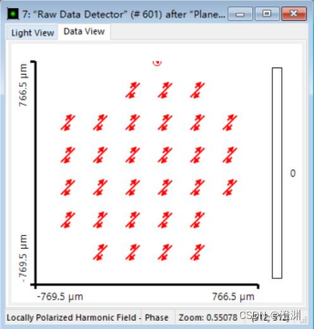
Set the plane wave angle to 0°, The operation results are as follows .
alike , Set the plane wave angle to 15°, After operation , The following result graph can be obtained .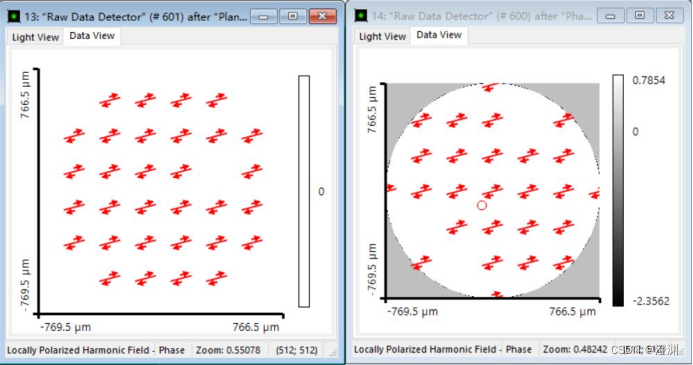
In fact, the key to the use of phase-shifting elements is that it will not affect the final polarization state , It's just right x and y The same phase delay is added to all directions .
2、 Birefringent crystal
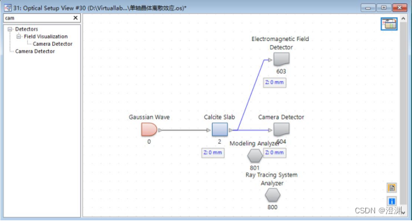
Next, the discrete effect simulation of uniaxial crystal . First add a Gaussian light .
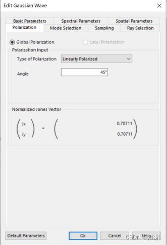
Double click to set it , Set here as a 633nm The red light , And set the initial polarization angle to 45°.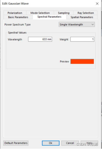
Next , Add calcite crystals ,Calcite Slab( This is a programmable element ,7.6.1.18 No alternative has been found in version , If you need codes and cases, please chat in private ).
Add two more detectors ,Electromagnetic Field Detector( This is a detector that can only be displayed by direction , That is, there will be multi graph mode when it is displayed , Need to be in ribbon Switch in the upper left corner , see x\y\z The light field component on the axis ) and Camera Detector. thus , The light path map is completed .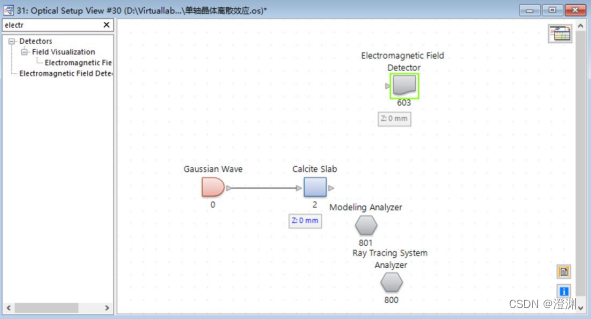
Click on the run , Use Manipulations Under the Create Numerical Data Array Process the obtained image .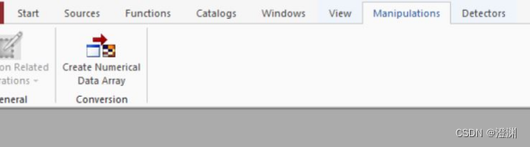
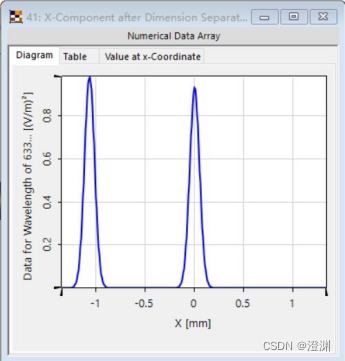
The following simulation images can be obtained .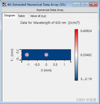
meanwhile , The following maximum values are obtained synchronously .( stay ribbon Medium detector The maximum and minimum values can be obtained under , Refer to the section of blazed grating )
For calcite , n 0 n_0 n0=1.6557, n e n_e ne=1.4852(λ=633nm), Using the discrete angle calculation formula , You can work out t a n α tan\alpha tanα, So as to calculate the corresponding maximum position (e Where the light passes through the birefringent crystal ) about -1.07mm.
3、 ... and 、 Effect display
Here we mainly show the effect of birefringent crystal experiment , By the way, deepen your understanding of birefringence .
1、 Change the direction of polarization
More specifically , Set the polarization direction to 0°( Along the x Axis direction , That is to say, there is no y The component of the axis ).
The experimental results after operation are as follows .
here , The light spot on the right disappears . We know that after birefringent crystal ,e Light will follow x Axis direction ,o Light will follow y Axis direction , Since the polarization direction set at the beginning does not y The component of the axis , Therefore, the experiment can only see e light , Out of sight o light .
Set the polarization angle to 90°.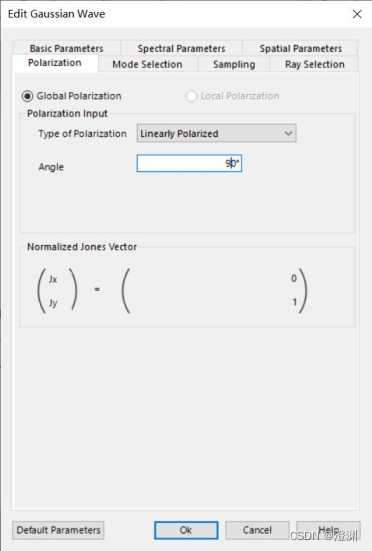
The experimental results after operation are as follows .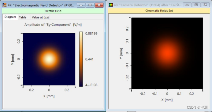
here , There is only one light spot in the operation result . Accordingly , At this time only o light , No, e light .
Set the polarization angle to 15°.
The experimental results after operation are as follows .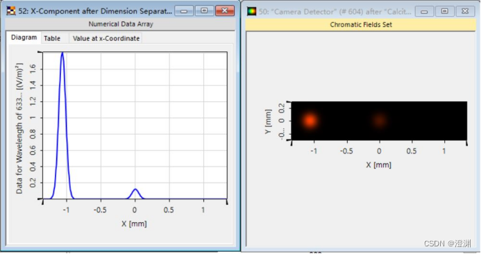
here , The left light spot is bright , The brightness of the light spot on the right is dark , The experimental results are consistent with the analysis .
Then modify the parameters of calcite , Change the thickness of calcite to 6mm.
2、 Change the thickness of calcite
Then modify the parameters of calcite , Change the thickness of calcite to 6mm( In the previous experiment, we have been set as 12mm).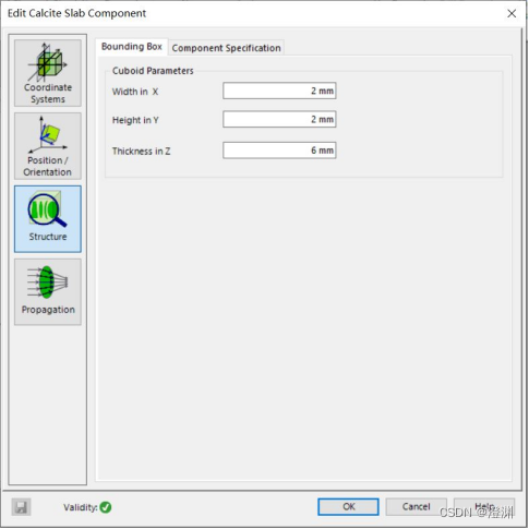
The experimental results after operation are as follows .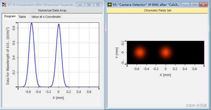
The maximum value is as follows .
By the formula Δ L = d t a n α \Delta L=dtan\alpha ΔL=dtanα, The thickness of calcite is halved , Theoretically, the corresponding maximum position is also reduced by half , The position of the maximum value measured in the experiment is about -533.6um, Consistent with the theory .
3、 Change the direction of the optical axis
Last , Modify the optical axis of calcite .( In the previous experiment, the optical axis and z The included angle of the shaft is 60°, Note that the first parameter in the setting is the same as the optical axis x The included angle of the shaft cos, The second parameter is the same y The included angle of the shaft cos, Because we think in advance that the optical axis is xoz In the plane , This value naturally does not exist , The third parameter is that the optical axis is the same z Angle between axes , For now 45°, They are set to sin45° and cos45°)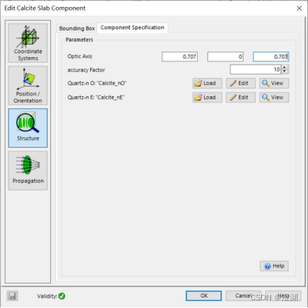
The experimental results after operation are as follows .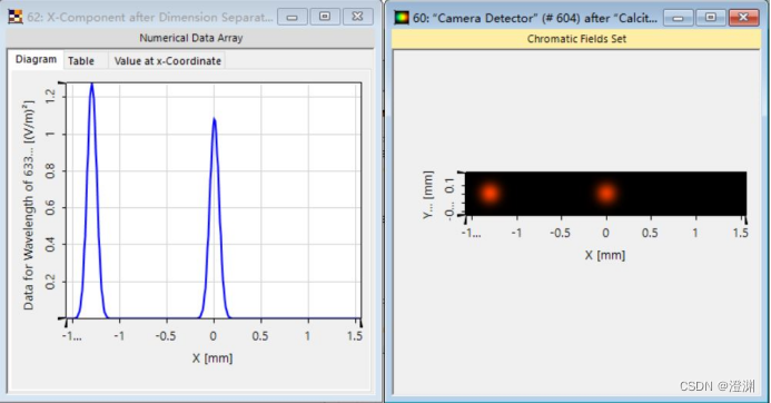
The maximum value is as follows .
here , The angle is changed from the original 60° Turn into 45°, similarly , Generation into the formula t a n α = 1 2 n e 2 − n 0 2 n o 2 s i n 2 θ + n e 2 c o s 2 θ s i n 2 θ tan\alpha=\frac{1}{2}\frac{n_e^2-n_0^2}{n_o^2sin^2\theta+n_e^2cos^2\theta}sin2\theta tanα=21no2sin2θ+ne2cos2θne2−n02sin2θ Calculation , The position where the maximum value can be obtained , The experimental results agree with the theoretical values .
summary
This article is written by members of Da Chuang team : Tang Yiheng 、 Help Yang Yu 、 Huang Yinuo 、 Li Sitong 、 Ming Yue jointly completed .
This article is only the rest of the polarization section , This article focuses on the study of birefringence , Because the author has not yet explored and found a way to replace calcite with non refractive elements , So now we use the existing cases for relevant research , If a friend finds an alternative operation , Welcome to exchange .
边栏推荐
- Migrate your accelerator based SAP commerce cloud storefront to Spartacus
- Five reasons to choose SAP Spartacus as the implementation framework of SAP commerce cloud storefront
- Alibaba Tianchi SQL learning notes - Day3
- 维护万星开源向量数据库是什么体验
- Common SQL statements (complete example)
- About me
- Schoolbag novel multithreaded crawler [easy to understand]
- ROS knowledge points -- the difference between ros:: nodehandle N and NH ("~")
- uva1169
- Leetcode question brushing record | 933_ Recent requests
猜你喜欢
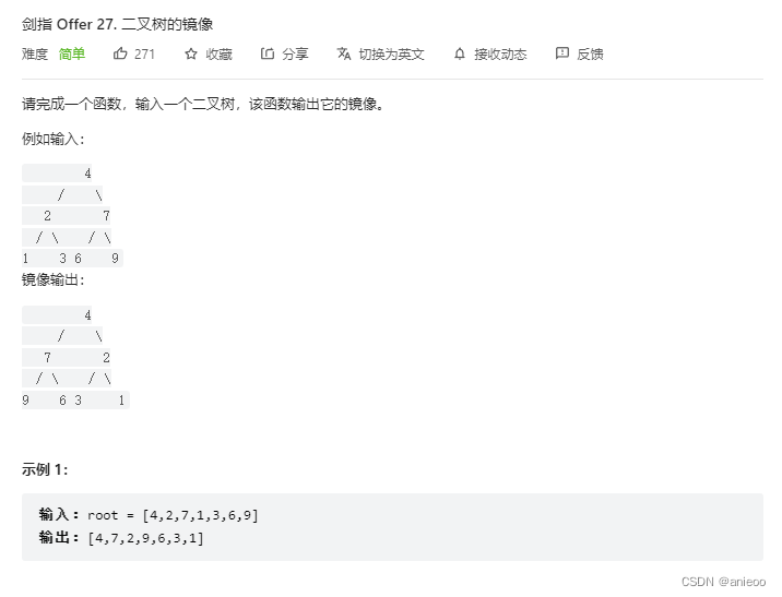
Sword finger offer 27 Image of binary tree
Example nonlinear integer programming
This "architect growth note" made 300 people successfully change jobs and enter the big factory, with an annual salary of 50W
![[shutter] dart data type (dynamic data type)](/img/6d/60277377852294c133b94205066e9e.jpg)
[shutter] dart data type (dynamic data type)

【网络是怎样连接的】第六章 请求到达服务器以及响应给客户端(完结)
Eth data set download and related problems
![List summation [dummy+ tail interpolation + function processing list reference common pit]](/img/08/30e8ca2376104d648a82dca8a72c42.png)
List summation [dummy+ tail interpolation + function processing list reference common pit]
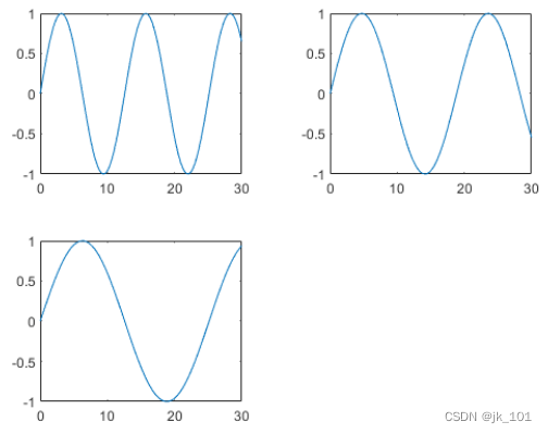
Use of nexttile function in MATLAB

简单线性规划问题

Daily question - inverted string
随机推荐
Nexus Introduction and Xiaobai use idea Packaging and Upload to Nexus 3 private service detailed tutoriel
executescalar mysql_ExecuteScalar()
[fluent] dart data type map type (create map set | initialize map set | traverse map set)
CEPH principle
[comment le réseau se connecte] chapitre 6: demande d'accès au serveur et réponse au client (terminé)
HBuilderX运行到手机或模拟器提示没有找到设备
em120.gige.h
选择 SAP Spartacus 作为 SAP Commerce Cloud Storefront 实现框架的五个理由
SAP commerce Cloud Architecture Overview
线性规划例题 投资的收益与风险
Ssm+ wechat applet to realize property management system
si446使用记录(二):使用WDS3生成头文件
USB interface powered Bluetooth color light strip controller
Alibaba Tianchi SQL learning notes - Day3
VScode知识点——常见报错
Séparateur JS3 de niuke
SAP Commerce Cloud 架构概述
【网络是怎么连接的】第四章 探索接入网和网络运营商
嵌入式开发板 ~ 说明
AtCoder Beginner Contest 237 VP补题