当前位置:网站首页>Multi camera data collection based on Kinect azure (III)
Multi camera data collection based on Kinect azure (III)
2022-06-22 07:06:00 【GaryW666】
be based on Kinect Azure Multi camera data acquisition ( 3、 ... and )
Based on Kinect Azure Multi camera data acquisition ( One ) and be based on Kinect Azure Multi camera data acquisition ( Two ) in , We summarized the use of Kinect Azure The method of collecting 3D color point cloud by camera and the synchronization method between cameras . If camera synchronization is the basis of multi camera acquisition system , Then the point cloud registration part is the key part of the system . Final acquisition quality , All rely on accurate point cloud registration results to ensure . therefore , This article continues to summarize the next part of the acquisition system —— Point cloud registration . If there is an incorrect or imprecise part , Welcome all bloggers to make corrections .
One 、 Point cloud registration
What is point cloud registration ? Popular speaking , Is to move all point clouds in different coordinate systems to the same coordinate system . For multiple cameras in different positions that have been synchronized , Each camera will get a three-dimensional image at different angles , In order to synthesize point clouds from different angles collected by multiple cameras into a complete point cloud , At this point, point cloud registration is required .
So how to perform point cloud registration ? First, let's think about how to move the point clouds collected by two cameras to the same coordinate system . For the main equipment , The point cloud coordinates collected by it are the coordinates under the coordinate system of its depth sensor , For slave devices , The coordinates of the point cloud collected by it are also the coordinates under the coordinate system of its depth sensor . At this time, what we need to do is to find the conversion relationship between the depth sensor coordinate system of the slave device and the depth sensor coordinate system of the master device , That is, the external parameters between the two coordinate systems . The external parameters between the depth sensor and the color sensor of each device are known , Then we only need to get the external parameters between the coordinate systems of the two equipment color sensors , You can move point clouds in different coordinate systems to the same coordinate system , That is to achieve point cloud registration . So how to get the external parameters between the color sensors of two devices ? There are two main methods : Camera calibration and coarse matching + Fine matching .
Two 、 Camera calibration
At present, the most commonly used calibration method is Zhang Zhengyou calibration method ( Black and white checkerboard calibration ). For a single sensor , This method can calculate the internal parameters of the sensor 、 Distortion parameters and external parameters between sensor coordinate system and world coordinate system . For both sensors , External parameters between them can be calculated . This section first summarizes the principle of Zhang Zhengyou's calibration method , Then explain how to pass opencv Library to implement .
1、 Principle of Zhang Zhengyou calibration method
Through the collected corners of the chessboard in the coordinates of the pixel coordinate system and the world coordinate system , The following relationship can be established ( The transformation relationship between coordinate systems is Kinect Azure Multi camera data acquisition ( One ) Has been described in ):
s m = K [ R , t ] M , Make H = λ K [ R , t ] , be m = H M sm=K[R,t]M, Make H=\lambda K[R,t], be m=HM sm=K[R,t]M, Make H=λK[R,t], be m=HM among ,s Is the scale factor ,m Is the pixel coordinate system coordinates ,M Is the world coordinate system ( The chessboard plane is Z=0).H by 8 Homography matrix of degrees of freedom , Theoretically, it can be solved by four pairs of matching corners .
because H = [ h 1 , h 2 , h 3 ] = λ K [ r 1 , r 2 , t ] H=[h_{1},h_{2},h_{3}]=\lambda K[r_{1},r_{2},t] H=[h1,h2,h3]=λK[r1,r2,t] r 1 = λ K − 1 h 1 , r 2 = λ K − 1 h 2 , t = λ K − 1 h 3 r_{1}=\lambda K^{-1}h_{1},r_{2}=\lambda K^{-1}h_{2},t=\lambda K^{-1}h_{3} r1=λK−1h1,r2=λK−1h2,t=λK−1h3 And R It has orthogonality and normalization , therefore r 1 ⋅ r 2 = 0 ⇒ h 1 T K − T K − 1 h 2 = 0 r_{1}\cdot r_{2}=0\Rightarrow h_{1}^{T}K^{-T}K^{-1}h_{2}=0 r1⋅r2=0⇒h1TK−TK−1h2=0 ∥ r 1 ∥ = ∥ r 2 ∥ ⇒ h 1 T K − T K − 1 h 1 = h 2 T K − T K − 1 h 2 \left\|r_{1}\right\|=\left\|r_{2}\right\| \Rightarrow h_{1}^{T} K^{-T} K^{-1} h_{1}=h_{2}^{T} K^{-T} K^{-1} h_{2} ∥r1∥=∥r2∥⇒h1TK−TK−1h1=h2TK−TK−1h2 One H A matrix can provide two equations , about 5 Degree of freedom K, At least three pictures are needed to solve . But the above derivation results are based on the solution in the ideal case , Because there may be Gaussian noise , Therefore, the maximum likelihood estimation is used for optimization . Use more pictures (20 Valid pictures ), Each picture has more corners (8*6 Chessboard ).
According to the above principle, the external parameters of a single sensor can be obtained , The external parameters of the color sensors of the two devices are obtained respectively , The external parameters between the two color sensors can be calculated .
2、 Camera calibration is realized
Can pass opencv Library to achieve camera calibration , Import header file calib3d.hpp. Use opencv The steps of camera calibration are as follows .
- The camera acquires a frame of image , From image format to Mat matrix
- utilize findChessboardCorners() Function to identify the position of checkerboard corner in an image
- drawChessboardCorners() Function to check whether the identified corner position is accurate
- When there are enough pictures , call calibrateCamera() To obtain distortion coefficient of the single camera ; call stereoCalibrate() To obtain the external parameters between the two cameras (R、t)
3、 ... and 、 Rough match + Fine matching
Point cloud registration can also be achieved through rough matching + The method of fine matching . Rough match , For both devices , Find the feature points on the collected images , And match the feature points , recycling SLAM The method of antipolar geometry in , Find out a set of rough external parameter solutions . Fine matching , utilize icp Method iterative solution , The solution obtained by rough matching calculation is taken as icp The initial solution of the algorithm , call pcl library , It can be done by icp The algorithm calculates the exact external parameters .
1、 Rough match
Feature point matching algorithm can be used , First, find the matching feature points on the image . Re pass SLAM Find a rough solution to polar geometry .
Feature point matching algorithm can be selected sift Algorithm or orb Algorithm .sift( Scale invariant feature transformation ) Algorithm , seeing the name of a thing one thinks of its function , It will have some special points , Not because of the change of perspective 、 Changes in light 、 The point at which noise disappears , As feature points . and orb(Oriented Fast and Rotated Brief ) Algorithm , It is through Fast Algorithm to find feature points , Find out what makes you stand out , Take a point and compare it with the points around it , If it is different from most of the points, it can be considered as a feature point . therefore ,orb The algorithm extracts feature points faster , but sift The robustness of the algorithm is better .
Can pass opencv Library implementation orb/sift Algorithm , Header files need to be imported features2d.hpp.
| orb | sift | |
|---|---|---|
| Create objects | Ptr orb = ORB::create(); | SiftFeatureDetector siftDetect; SiftDescriptorExtractor descriptor; |
| Extracting feature points | orb->detect(); | siftDetect.detect(); |
| Computational descriptors | orb->compute(); | descriptor.compute(); |
| Create objects for matching | BFMatcher matcher(); | Ptr matcher = DescriptorMatcher::create(); |
| Matching feature points | matcher.match(); | matcher->match(); |
2、SLAM Polar geometry
After the above rough matching process , You can get a series of matching pixels , It can be obtained by the method of antipolar geometry R、t A set of solutions . use p 1 , p 2 p_{1},p_{2} p1,p2 To represent two sets of matching pixel coordinates , use P P P Express p 1 p_{1} p1 Coordinates under the corresponding camera coordinate system , Then there is the following relation : s 1 p 1 = K P , s 2 p 2 = K ( R P + t ) s_{1} p_{1}=K P, s_{2} p_{2}=K(R P+t) s1p1=KP,s2p2=K(RP+t) x 1 = s 1 K − 1 p 1 , x 2 = s 2 K − 1 p 2 , x 2 = R x 1 + t x_{1}=s_{1} K^{-1} p_{1}, x_{2}=s_{2} K^{-1} p_{2}, x_{2}=R x_{1}+t x1=s1K−1p1,x2=s2K−1p2,x2=Rx1+t t ∧ x 2 = t ∧ R x 1 + t ∧ t = t ∧ R x 1 t^{\wedge} x_{2}=t^{\wedge} R x_{1}+t^{\wedge} t=t^{\wedge} R x_{1} t∧x2=t∧Rx1+t∧t=t∧Rx1 x 2 T t ∧ R x 1 = x 2 T t ∧ x 2 = 0 x_{2}^{T} t^{\wedge} R x_{1}=x_{2}^{T} t^{\wedge} x_{2}=0 x2Tt∧Rx1=x2Tt∧x2=0 p 2 T K − T t ∧ R K − 1 p 1 = 0 p_{2}^{T} K^{-T} t^{\wedge} R K^{-1} p_{1}=0 p2TK−Tt∧RK−1p1=0 E = t ∧ R ( Ben quality Moment front ) , F = K − T E K − 1 ( The base Foundation Moment front ) E=t^{\wedge}R( The essential matrix ),F=K^{-T}EK^{-1}( Basic matrix ) E=t∧R( Ben quality Moment front ),F=K−TEK−1( The base Foundation Moment front )
- E/F by 8 Degree of freedom matrix , Each pair of matching points provides an equation , At least 8 Points can be solved E/F. When there are too many matching points, we can solve the overdetermined equation E/F
- E The singular value of satisfies [ σ , σ , 0 ] [\sigma,\sigma,0] [σ,σ,0],σ Is the scale factor , Can be calculated E E T EE^{T} EET To prove that
- Yes E Conduct SVD decompose , E = U Σ V T = ( U Σ 1 U T ) ∗ ( U Σ 2 V T ) , Σ = Σ 1 Σ 2 E=U \Sigma V^{T}=\left(U \Sigma_{1} U^{T}\right) *\left(U \Sigma_{2} V^{T}\right), \Sigma=\Sigma_{1} \Sigma_{2} E=UΣVT=(UΣ1UT)∗(UΣ2VT),Σ=Σ1Σ2, The former is an antisymmetric matrix (t^), The latter is an orthogonal matrix (R)
- Due to the existence of scale factor , Found t There may be positive and negative ; Due to different rotation directions ,R There are also two situations . So there are four sets of solutions , But only one set of solutions satisfies P The depth is positive in both coordinate systems , The depth can be calculated by triangulation
- Triangulation :
s 1 p 1 = K P , s 2 p 2 = K ( R P + t ) s_{1} p_{1}=K P, s_{2} p_{2}=K(R P+t) s1p1=KP,s2p2=K(RP+t) s 2 K − 1 p 2 = R ( s 1 K − 1 p 1 + t ) s_{2} K^{-1} p_{2}=R\left(s_{1} K^{-1} p_{1}+t\right) s2K−1p2=R(s1K−1p1+t) p 2 ∧ K R ( s 1 K − 1 p 1 + t ) = s 2 p 2 ∧ K K − 1 p 2 = 0 → p_{2}^{\wedge} K R\left(s_{1} K^{-1} p_{1}+t\right)=s_{2} p_{2}^{\wedge} K K^{-1} p_{2}=\overrightarrow{0} p2∧KR(s1K−1p1+t)=s2p2∧KK−1p2=0 s 1 p 2 ∧ K R K − 1 p 1 = − p 2 ∧ K R t s_{1} p_{2}^{\wedge} K R K^{-1} p_{1}=-p_{2}^{\wedge} K R t s1p2∧KRK−1p1=−p2∧KRt
Find out s1 after , Carry in and calculate P, And then find out s2, if s1 and s2 All are greater than 0, Then the group solution is correct R、t. - Can also pass opencv Library findEssentialMat/findFundamentalMat Function solving E/F matrix , adopt recoverPose Function solving R、t
3、 Fine matching
utilize ICP(point2point,point2plane etc. ) Algorithm , The external parameters obtained by rough matching are used as ICP The initial solution of the algorithm , call PCL library , Realization ICP Algorithm , So as to obtain the external parameters .
Through the above camera calibration or rough matching + The method of fine matching , External parameters between color sensors can be obtained , Thus, the external parameters between the two equipment depth sensors are calculated , And through external parameters , Move the two point cloud data to the same coordinate system , Compose a complete 3D image .
thus , The whole system is set up , Review the whole process of the system again . First, synchronize multiple cameras , Make the data they get at the same time . then , Each camera collects and processes data separately . Last , Through point cloud registration, 3D images from different angles collected by multiple devices , Move to the same coordinate system , Synthesize a complete point cloud data .
After the acquisition system is completed , You can continue to build a complete collection 、 Compress 、 transmission 、 Display system . adopt windows Use of multithreading , Collect data 、 Data processing 、 Data transmission is divided into multiple threads , The collected data can be displayed in the client in real time .
边栏推荐
- Article editing test of CSDN
- Difference between grail layout and twin wing layout
- Implement a timer: timer
- C语言——深入理解数组
- Self supervised learning for general out of distribution detection AAAI '20
- 2022年畢業生求職找工作青睞哪個行業?
- golang调用sdl2,播放pcm音频,报错signal arrived during external code execution。
- Custom implementation of bind method in JS
- [out of distribution detection] energy based out of distribution detection nips' 20
- 【GAN】SentiGAN IJCAI’18 Distinguished Paper
猜你喜欢

Correspondence between pytorch and torchvision
Introduction notes to quantum computing (continuously updated)

Fundamentals of neural network (notes, for personal use)

Developing a contract application with low code

校招路上的坑

流程引擎解决复杂的业务问题
![[anomaly detection] malware detection: mamadroid (dnss 2017)](/img/dd/37a443fce627f7f38e3fe1767cb10e.jpg)
[anomaly detection] malware detection: mamadroid (dnss 2017)
![[out of distribution detection] learning confidence for out of distribution detection in neural networks arXiv '18](/img/07/d5479dde181c355d95c73e2f58c0da.jpg)
[out of distribution detection] learning confidence for out of distribution detection in neural networks arXiv '18

ROS Qt环境搭建
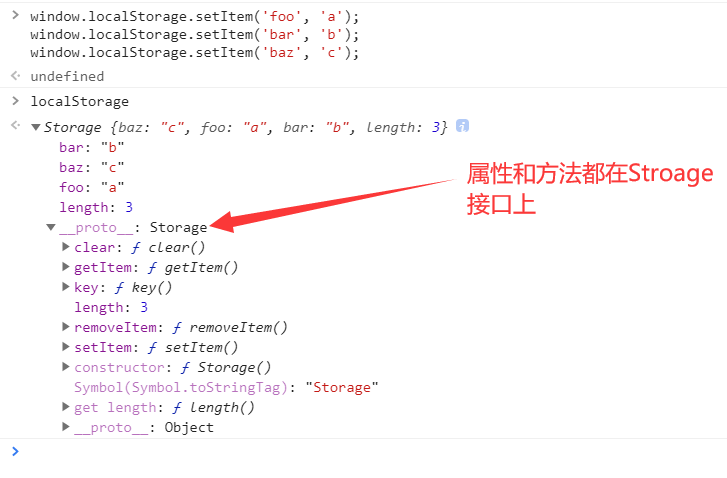
sessionStorage 和 localStorage 的使用
随机推荐
Py之scorecardpy:scorecardpy的简介、安装、使用方法之详细攻略
Qt development simple Bluetooth debugging assistant (low power Bluetooth)
CNN model collection | RESNET variants -wideresnet interpretation
iframe框架,,原生js路由
Assembly learning Chapter 4 of assembly language (Third Edition) written by Wang Shuang
June 21, 2022: golang multiple choice question, what does the following golang code output? A:3; B:4; C:100; D: Compilation failed. package main import ( “fmt“ ) func
About pointer (notes, for personal use)
首次用DBeaver连接mysql报错
sessionStorage 和 localStorage 的使用
Self supervised learning for general out of distribution detection AAAI '20
The journey of an operator in the framework of deep learning
[outside distribution detection] your classifier is secret an energy based model and you head treat it like one ICLR '20
Thousands of sails pass by the side of the sunken boat, and thousands of trees spring before the diseased tree
RT-Thread临界段的保护
June training (day 22) - orderly gathering
Introduction to 51 Single Chip Microcomputer -- the use of Proteus 8 professional
Xh_ CMS penetration test documentation
An image is worth 16x16 words: translators for image recognition at scale
Error when connecting MySQL with dbeaver for the first time
[fundamentals of machine learning 01] blending, bagging and AdaBoost