当前位置:网站首页>Switching power supply circuit diagram and principle 12V analysis - detailed version
Switching power supply circuit diagram and principle 12V analysis - detailed version
2022-06-11 16:33:00 【Tree card flower】
Circuit diagram and principle of switching power supply 12v( Circuit diagram and principle of switching power supply )
Explain the circuit diagram and principle of switching power supply , For reference only !
1、 Switching power supply circuit composition
The main circuit of switching power supply is input EMI filter (EMI)、 Rectifier filter circuit 、 Power conversion circuit 、PWM Controller circuits 、 The output rectifying and filtering circuit is composed of .
The auxiliary circuit has input overvoltage and undervoltage protection circuit 、 Output overvoltage and undervoltage protection circuit 、 Output over current protection circuit 、 Output short circuit protection circuit, etc .
The circuit composition block diagram of switching power supply is as follows :

2、 The principle of input circuit and common circuit
(1)AC Principle of input rectifier filter circuit :

① Lightning protection circuit : When lightning strikes , When high voltage is generated and introduced into the power supply through the power grid , from MOV1、MOV2、MOV3:F1、F2、F3、FDG1 The composition of the circuit to protect . When the voltage applied to both ends of the varistor exceeds its working voltage , Its resistance is reduced , High voltage energy is consumed on varistors , If the current is too high ,F1、F2、F3 It will burn down the protection circuit .
② Input filter circuit :C1、L1、C2、C3 Made up of two π The main purpose of this paper is to suppress the electromagnetic noise and clutter signal of the input power supply , Prevent interference with power supply , At the same time, it also prevents the high frequency clutter generated by the power supply itself from interfering with the power grid . When the power is on , Right C5 Charge , Because of the high instantaneous current , Add RT1( Thermistor ) Can effectively prevent surge current . Because the instantaneous energy is consumed in RT1 On the resistance , After a certain time, the temperature rises RT1 The resistance decreases (RT1 It's a negative temperature coefficient element ), At this point, it consumes very little energy , The back stage circuit can work normally .
③ Rectifier filter circuit : The AC voltage passes through BRG1 After rectification , the C5 After filtering, the pure DC voltage is obtained . if C5 The capacity gets smaller , The output AC ripple will increase .
(2)DC Principle of input filter circuit :

① Input filter circuit :C1、L1、C2 Made up of two π The main purpose of this paper is to suppress the electromagnetic noise and clutter signal of the input power supply , Prevent interference with power supply , At the same time, it also prevents the high frequency clutter generated by the power supply itself from interfering with the power grid .C3、C4 For the safety of capacitors ,L2、L3 It is a differential mode inductor .
② R1、R2、R3、Z1、C6、Q1、Z2、R4、R5、Q2、RT1、C7 Constitute anti surge circuit . At the moment of starting the machine , because C6 The existence of Q2 No conduction , Electricity flows through RT1 Make up the loop .
When C6 Charge the voltage on to Z1 When the voltage value of Q2 Conduction . If C8 Leakage or short circuit in the following circuit , At the moment of starting the machine, the current is in RT1 The resulting pressure drop on the ,Q1 Turn on to make Q2 No gate voltage, no conduction ,RT1 It will burn down in a short time , In order to protect the later stage circuit .
3、 Power conversion circuit
(1)MOS How the tube works :
At present, the most widely used IGFET is MOSFET(MOS tube ), It works by using the electroacoustic effect of the semiconductor surface . Also known as surface field effect devices . Because its gate is not conductive , So the input resistance can be greatly increased , Up to 105 ohm ,MOS The tube uses the gate source voltage , To change the amount of surface induced charge on a semiconductor , So as to control the drain current .
(2) Common schematic diagram :
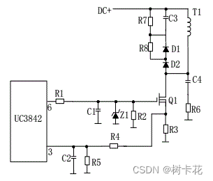
(3) working principle :
R4、C3、R5、R6、C4、D1、D2 Make up the buffer , And the switch MOS Parallel connection of pipes , Reduce the voltage stress of switch tube ,EMI Reduce , No secondary breakdown occurs .
In the switch tube Q1 When off , The primary coil of transformer is easy to produce peak voltage and peak current , These elements come together , It can absorb peak voltage and current very well .
from R3 The measured peak current signal participates in the duty cycle control of the current working cycle , Therefore, it is the current limit of the current working cycle . When R5 The voltage on is up to 1V when ,UC3842 Stop working , Switch tube Q1 Turn off immediately .
R1 and Q1 The junction capacitance in CGS、CGD Together make up RC The Internet , The charge and discharge of capacitor directly affects the switching speed of switch tube .R1 Too small , It is easy to cause oscillation , Electromagnetic interference can also be very large ;R1 Too big , It will reduce the switching speed of the switch tube .
Z1 Will usually MOS Tubular GS The voltage is limited to 18V following , Thus protecting MOS tube .Q1 The grid controlled voltage is saw wave , When its duty cycle is higher ,Q1 The longer the conduction time is , The more energy the transformer stores ;
When Q1 At the deadline , The transformer passes through D1、D2、R5、R4、C3 Release energy , At the same time, it achieves the purpose of magnetic field reset , For the next storage of the transformer 、 Ready to deliver energy .
IC Adjust according to the output voltage and current ⑥ The size of the foot saw duty cycle , Thus, the output current and voltage of the whole machine are stabilized .C4 and R6 Peak voltage absorption circuit .
(4) Push pull power conversion circuit :
Q1 and Q2 Will turn on .
(5) A power conversion circuit with a drive transformer :
T2 For the drive transformer ,T1 For switching transformer ,TR1 It's the current loop .
4、 Output rectifier filter circuit
(1) Forward rectifier circuit :
T1 For switching transformer , The phases of the primary and secondary poles are in phase .D1 For rectifying diode ,D2 For freewheeling diode ,R1、C1、R2、C2 To cut the spike circuit .L1 Is the freewheeling inductor ,C4、L2、C5 form π Type a filter .
(2) Flyback rectifier :
T1 For switching transformer , The phases of the primary and secondary poles are opposite .D1 For rectifying diode ,R1、C1 To cut the spike circuit .L1 Is the freewheeling inductor ,R2 It's a fake load ,C4、L2、C5 form π Type a filter .
(3) Synchronous rectifier circuit :
working principle : When the upper end of transformer secondary is positive , Electricity flows through C2、R5、R6、R7 send Q2 Conduction , The circuit forms the loop ,Q2 For rectifiers .Q1 Because the gate is in reverse bias . When the lower end of the transformer secondary is positive , Electricity flows through C3、R4、R2 send Q1 Conduction ,Q1 For the afterflow tube .Q2 Because the gate is in reverse bias .L2 Is the freewheeling inductor ,C6、L1、C7 form π Type a filter .R1、C1、R9、C4 To cut the spike circuit .
5、 Principle of voltage stabilizing loop
(1) Feedback circuit schematic :

(2) working principle :
When the output U0 elevated , By sampling resistance R7、R8、R10、VR1 After partial pressure ,U1③ The foot voltage rises , When it exceeds U1② After the pin reference voltage U1① Pin output high level , send Q1 Conduction , Optocoupler OT1 Light emitting diodes give off light , The photoelectric triode is on ,UC3842① The potential of the foot drops accordingly , To change U1⑥ The duty cycle of the foot output decreases ,U0 Reduce .
When the output U0 When lowering ,U1③ The foot voltage drops , When it is lower than U1② After the pin reference voltage U1① Pin output low level ,Q1 No conduction , Optocoupler OT1 Led doesn't light up , The photoelectric triode is not conducting ,UC3842① The foot potential goes up , To change U1⑥ The duty cycle of the foot output increases ,U0 Reduce . Go round and begin again , So that the output voltage remains stable . Adjust the VR1 The output voltage can be changed .
Feedback loop is an important circuit that affects the stability of switching power supply . If the feedback resistor capacitor is wrong 、 leak 、 False welding, etc , There will be self-excited oscillation , The fault phenomenon is : Abnormal waveform , empty 、 Full load oscillation , Unstable output voltage, etc .
6、 Short circuit protection circuit
In the case of output short circuit ,PWM The control circuit can limit the output current to a safe range , It can be implemented in a variety of ways , When power current limiting does not work in short circuit , Only another part of the circuit is added .
(1) There are usually two kinds of short circuit protection circuits , The figure below shows the low power short circuit protection circuit , Its principle is described as follows :
When the output circuit is short circuited , The output voltage disappears , Optocoupler OT1 No conduction ,UC3842① The foot voltage rises to 5V about ,R1 And R2 Its partial pressure exceeds TL431 The benchmark , Make it work ,UC3842⑦ foot VCC The potential is pulled down ,IC Stop working .
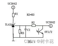
UC3842 After stopping work ① The foot potential disappears ,TL431 No conduction UC3842⑦ The foot potential goes up ,UC3842 Restart , Go round and begin again . When the short circuit disappears , The circuit can return to normal working state automatically .
(2) The figure below shows the medium power short circuit protection circuit , Its principle is described as follows :
When the output is short circuited ,UC3842① The foot voltage goes up ,U1③ The foot potential is higher than ② Foot time , Comparator flip ① Foot output high potential , to C1 Charge , When C1 The voltage at both ends exceeds ⑤ When the pin reference voltage U1⑦ Foot output low potential ,UC3842① Feet below 1V,UCC3842 Stop working , The output voltage is 0V, Go round and begin again , When the short circuit disappears, the circuit works normally .R2、C1 It's the charge discharge time constant , No short circuit protection .

(3) The following figure shows the common current limiting 、 Short circuit protection circuit . Its working principle is described as follows :
When the output circuit is short circuited or over current , The primary side current of transformer increases ,R3 The voltage drop at both ends increases ,③ The foot voltage rises ,UC3842⑥ The duty cycle of foot output increases gradually ,③ The foot voltage exceeds 1V when ,UC3842 Turn off no output .

(4) The following figure shows the protection circuit of sampling current with current transformer , It has low power consumption , But the cost is high and the circuit is more complex , Its working principle is described as follows :
Output circuit short circuit or excessive current ,TR1 The higher the voltage induced by the secondary coil , When UC3842③ Feet over 1 v ,UC3842 Stop working , Go round and begin again , When the short circuit or overload disappears , The circuit recovers itself .

7、 Output current limiting protection
The above figure is a common output current limiting protection circuit , Its working principle is described in the figure above : When the output current is too high ,RS( Manganese copper wire ) Voltage rise at both ends ,U1③ The pin voltage is higher than ② Pin reference voltage ,U1① Pin output high voltage ,Q1 Conduction , Optocoupler has photoelectric effect ,UC3842① The foot voltage drops , The output voltage drops , So as to achieve the purpose of output overload current limiting .
8、 Principle of output overvoltage protection circuit
The function of output overvoltage protection circuit is : When the output voltage exceeds the design value , Limit the output voltage to a safe value . When the internal voltage stabilizing loop of switching power supply fails or the output overvoltage is caused by improper operation of users , The over-voltage protection circuit is used to protect the secondary electrical equipment .
The most common overvoltage protection circuits are as follows :
(1) Thyristor trigger protection circuit :
Pictured above , When Uo1 Output goes up , Regulator tube (Z3) Breakdown conduction , Thyristor (SCR1) The trigger voltage is obtained at the control end of , So the thyristor turns on .
Uo2 Voltage short circuit to ground , Over current protection circuit or short circuit protection circuit will work , Stop the entire power circuit . When the output over-voltage phenomenon is eliminated , The trigger voltage at the control end of the thyristor passes through R Discharge to the ground , The thyristor returns to the disconnected state .
(2) Photoelectric coupling protection circuit :
Pictured above , When Uo When there is overpressure , Voltage regulator tube breakdown conduction , By optocoupler (OT2)R6 To the ground produces an electric current flowing through , The light emitting diode of the optocoupler emits light , In this way, the photosensitive triode of the optocoupler is turned on .
Q1 The base must be electrically conductive ,3842 Of ③ The foot electricity is reduced , send IC close , Stop the entire power supply ,Uo zero , Go round and begin again .
(3) Output voltage limiting protection circuit :
The output voltage limiting protection circuit is shown in the figure below , When the output voltage rises , The voltage stabilizing tube is on, and the optocoupler is on ,Q1 The base has a driving voltage and the channel is connected ,UC3842③ The voltage goes up , Output goes down , The voltage stabilizing tube doesn't work ,UC3842③ Voltage drop , The output voltage rises . Go round and begin again , The output voltage will be stable in a range ( It depends on the voltage stabilizing value of the regulator tube ).
(4) Output over voltage locking circuit :
chart A It works by , When the output voltage Uo elevated , The regulator is on , The optocoupler is on ,Q2 The base must be electrically conductive , because Q2 On of Q1 When the base voltage decreases, it turns on ,Vcc The voltage goes through R1、Q1、R2 send Q2 Always on ,UC3842③ The foot is always high and stops working .
In the figure B in ,UO elevated U1③ The foot voltage rises ,① Pin output high level , because D1、R1 The existence of ,U1① The pin always outputs high level Q1 Always on ,UC3842① The foot is always low and stops working .
9、 Power factor correction circuit (PFC)
(1) Schematic diagram :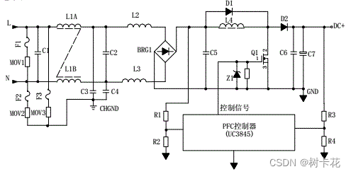
(2) working principle :
The input voltage passes through L1、L2、L3 And so on EMI filter ,BRG1 All the way through rectification PFC inductance , Another way R1、R2 After partial pressure, feed in PFC The controller samples the input voltage , To adjust the duty cycle of the control signal , That is change Q1 On and off time of , Stable PFC Output voltage .
L4 yes PFC inductance , It's in Q1 It stores energy when it's on , stay Q1 When you turn off, cast energy .D1 It's a starter diode .D2 yes PFC Rectifier diode ,C6、C7 wave filtering .PFC The voltage is sent to the back stage circuit , Another way R3、R4 After partial pressure, feed in PFC The controller acts as PFC Sampling of output voltage , To adjust the duty cycle of the control signal , Stable PFC Output voltage .
10、 Under voltage input protection
(1) Schematic diagram :

(2) working principle :
AC Input and DC The input overvoltage and undervoltage protection principle of the input switching power supply is roughly the same . The sampling voltage of the protection circuit comes from the input filtered voltage .
The sampling voltage is divided into two circuits , All the way through R1、R2、R3、R4 After partial voltage input comparator 3 foot , If the sampling voltage is higher than 2 Pin reference voltage , The comparator 1 The pin outputs a high level to control the main controller to turn it off , The power supply has no output .
Another way R7、R8、R9、R10 After partial voltage input comparator 6 foot , If the sampling voltage is lower than 5 Pin reference voltage , The comparator 7 The pin outputs a high level to control the main controller to turn it off , The power supply has no output .
KIA Semiconductors are widely used in inverters 、 Lithium battery protection board 、 Electric vehicle controller 、HID Automative lighting 、LED The lamp 、 No brush motor 、 Miner power supply 、 Industrial power supply 、 Adapter 、3D Printer and other fields ;KIA semiconductor MOS Tube has a great core competitiveness , It is the best choice for switching power supply manufacturers .KIA semiconductor MOS Tube manufacturers mainly research and develop 、 production 、 business : Field effect tube (MOS tube )、COOLMOS( Superjunction FET )、 Three terminal regulator 、 Fast recovery diode ; Can apply for samples and quotations and have technical support , If there is any problem, technicians can help solve the problem !
边栏推荐
- leetcode417. Pacific Atlantic current problems (medium)
- 2022年安全员-B证国家题库及模拟考试
- How to optimize the performance of compose? Find the answer through "underlying principles" | developers say · dtalk
- leetcode684. 冗余连接(中等)
- 2022起重机司机(限桥式起重机)考试题模拟考试题库及模拟考试
- RSP: An Empirical Study of remote sensing pre training
- Go语言之Go 快速入门篇(一):第一个 Go 程序
- Analysis of time complexity and space complexity
- [leetcode daily question] Repeat overlay string matching
- TC8:UDP_ MessageFormat_ 01-02
猜你喜欢

The micro service failed to connect to the cloud sentinel console and the link blank problem occurred after the connection was successful (resolved)

【剑指Offer】21.调整数组顺序使奇数位于偶数前面

What is a generic? Why use generics? How do I use generics? What about packaging?

Pytest test framework Basics

C# 启动一个外部exe文件,并传入参数

2022 high altitude installation, maintenance and demolition test simulation 100 questions and online simulation test

Ruiji takeout project (III) employee management business development
MySQL快速入门实例篇(入内不亏)

laravel 监听模式

整了20张高清数据分析全知识地图,强烈建议收藏!
随机推荐
leetcode463. 岛屿的周长(简单)
【剑指Offer】21.调整数组顺序使奇数位于偶数前面
Toolbar details of user interface - autorunner automated test tool
Solve the problem that jupyter cannot connect to the kernel based on pycharm and Anaconda -- solution 1
Oracle 分析函数 over 和MySQL 实现类似效果写法
What if the win10 security center cannot be closed
[sword finger offer] 22 The penultimate node in the linked list
2022起重机司机(限桥式起重机)考试题模拟考试题库及模拟考试
Rdkit installation
A team of heavyweights came to the "digital transformation" arena of CLP Jinxin ice and snow sports
unittest 如何知道每个测试用例的执行时间
How can the project manager repel the fear of being dominated by work reports?
leetcode463. Perimeter of the island (simple)
从0到1了解Prometheus
MySQL quick start instance (no loss)
leetcode417. 太平洋大西洋水流问题(中等)
485 days, 21 experiences of my remote office sharing | community essay solicitation
Detailed explanation of the functions of list and dict data types
List和Set存取元素的差异
完整的测试流程【杭州多测师】【杭州多测师_王sir】