当前位置:网站首页>Port multiplexing and re imaging
Port multiplexing and re imaging
2022-07-07 09:07:00 【A big cat 1201】
author : A big cat 1201
special column :《STM32 Study 》
Maxim : You just try to , Leave the rest to time !

Port reuse and remapping
describe
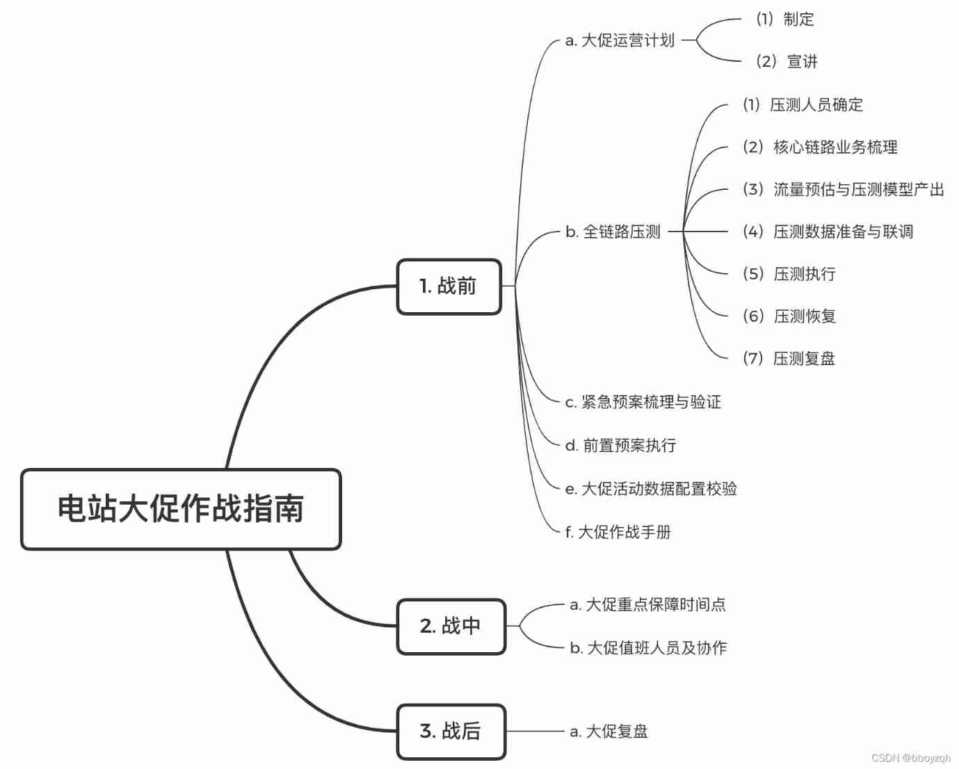
Let's take a look at one STM32 Simple structure diagram of 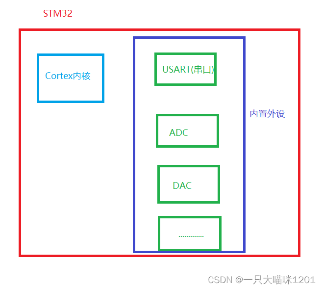
You can see that in the diagram , Except for the kernel ( That is to say CPU), Another part is built-in peripherals . There are many kinds of built-in peripherals , The number of built-in peripherals of different types of chips is also different , As used by benmew STM32F103ZET6 The serial port of the chip has 5 individual . These built-in peripherals are through GPIO Of Port multiplexing and Remapping To input and output signals
Port multiplexing
Concept :
One GPIO If it can be reused as a function pin of the built-in peripheral , So when this GPIO When used as a built-in peripheral , It's called reuse .
With USART1( A serial port 1) Take port multiplexing as an example .
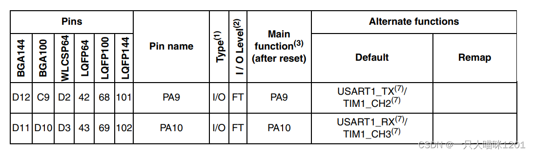
This is a STM32F103ZET6《 Data manual 》 A partial screenshot of the pin information description table in .
You can see
- PA9 and PA10 The main functions of PA9 and PA10. That is, general input and output function .
- Among the selectable functions, the default reuse function is USART1_TX( A serial port 1 Send pin ) and USART1_RX( A serial port 1 Receive pin ).
At this point we can say ,USART1_TX and USART1_RX Is reused in GPIO Of PA9 and PA10 Oral .
Configuration process of port multiplexing
After we know what class port reuse is, we need to configure it , How else can the chip know GPIO Is the port used as a general input and output port or a port multiplexing port ?
- GPIO Clock enable
Port reuse is still used in the final analysis GPIO, Therefore, it is necessary to check the corresponding GPIO Carry out enabling . With USART1 For example , We know that it reuses GPIO yes PA Of the group IO mouth , So you need to GPIOA Carry out enabling .
RCC_APB2PeriphClockCmd(RCC_APB2Periph_GPIOA, ENABLE);
In this meow's article STM32 Our clock system As mentioned in GPIO Is attached to APB2 Under the bus , So this function is used .
- Multiplex peripheral clock enable
No matter what peripherals are used , Not only does it use GPIO, And the peripheral itself should also be used , Therefore, when using built-in peripherals, it is also necessary to enable . With USART1 For example
RCC_APB2PeriphClockCmd(RCC_APB2Periph_USART1, ENABLE);
USART1( A serial port 1) It is also attached to APB2 On the bus .
- Port mode configuration
Will be GPIO and USAR1 Enable later , Next we need to tell CPU The IO The port uses the port multiplexing function .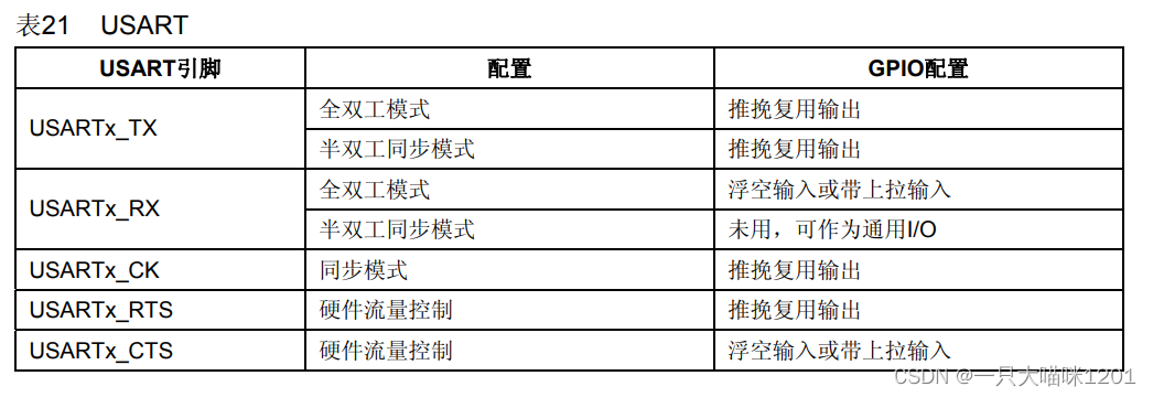
stay STM32F103ZET6 Chip 《 Chinese Reference Manual 》 In the reuse function configuration table , Lists in detail when port multiplexing ,GPIO How to configure . That is to say GPIO The initialization .
With USART1_TX and USART1_RX For example :
USART1_TX( The sender )
- In full duplex mode ,GPIO It needs to be configured into push-pull multiplexing output mode .
USART1_RX( The receiver )
- In full duplex mode ,GPIO It needs to be configured as floating input or pull-up input .
In the code
GPIO_TypeDef GPIO_InitStructyre;
GPIO_InitStructure.GPIO_Pin = GPIO_Pin_9; //PA.9// Multiplexing push pull output
GPIO_InitStructure.GPIO_Speed = GPIO_Speed_50MHz;
GPIO_InitStructure.GPIO_Mode = GPIO_Mode_AF_PP;
GPIO_Init(GPIOA, &GPIO_InitStructure);

GPIO_InitStructure.GPIO_Pin = GPIO_Pin_10;//PA10 PA.10  Floating input
GPIO_InitStructure.GPIO_Mode = GPIO_Mode_IN_FLOATING;// Floating input
GPIO_Init(GPIOA, &GPIO_InitStructure);
The above is based on USART1 For example , The whole process of port multiplexing configuration . After the above configuration ,PA9 and PA10 And it became USART1_TX and USART1_RX The pin of , It is no longer a general input and output port .
Port reimage
Port remapping is actually similar to port multiplexing , Port multiplexing is built-in peripherals, and the multiplexing port is fixed , It is necessary to find the multiplexing corresponding to different peripherals through the pin description in the data manual GPIO mouth .
The mapped port of port remapping is also fixed , It also needs to be found by looking up the table , The mapping port and multiplexing port are not the same .
Concept :
- The pin of a peripheral has a default port , You can also set the remapping register , Map the pins of this peripheral to other ports .
Purpose :
- In order to allow design engineers to better arrange the direction and function of pins , Potentially reduce the cross interference of signals .
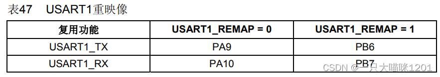
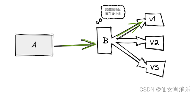
This is a STM32F103ZET6 chip 《 Chinese Reference Manual 》 Re image configuration table in . With USART1 For example , The table shows ,USART1_TX and USART1_RX After remapping GPIO The mouth is PB6 and PB7.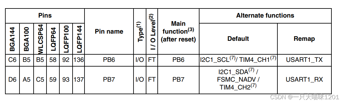
It can also be done through 《 Data manual 》 See in the pin description table in ,PB6 and PB7 Among the selectable functions , After remapping, the corresponding is USART1_TX and USART1_RX.
Port remapping is also divided into incomplete remapping and complete remapping
Partial re image and full re image
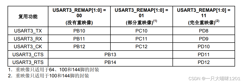
With USART3 For example , stay 《 Chinese Reference Manual 》 In the re image configuration table of ,USART3 A common need 5 One pin , Namely USART3_TX,USART3_RX,USART3_CK,USART3_CTS,USART3_RTS.
When there is no re image
- This 5 Ports use the port multiplexing function by default , They correspond to PB10 To PB14.
When partially reimaging
- among USART3_TX,USART3_RX,USART3_CK These three ports are no longer port multiplexed PB10 To PB12, But the remake became PC10 To PC12, and USART3_CTS and USART3_RTS It still corresponds to port multiplexing PB13 and PB14.
Complete remapping
- USART3 Of 5 All ports are reimagined to the new port , Corresponding PD8 To PD12 Five ports .
in general , Partial remapping refers to the remapping of some pins of built-in peripherals , There are also some pins corresponding to the default port multiplexing . Full remapping means that all pins of built-in peripherals are remapped .
The configuration process of re image
After knowing what is re image , We are going to use it .
- Enable remapped GPIO.
After remapping, the new GPIO, So it is necessary to enable , Only after enabling, should IO Eloquence will be opened . With USART3 For example :
When partially reimaging :
RCC_APB2PeriphClockCmd(RCC_APB2Periph_GPIOC, ENABLE);
RCC_APB2PeriphClockCmd(RCC_APB2Periph_GPIOB, ENABLE);
After partial remapping, two groups are used IO mouth , So you need to GPIOC and GPIOB Are enabled
Complete remapping
RCC_APB2PeriphClockCmd(RCC_APB2Periph_GPIOD, ENABLE);
After completely remapping ,USART3 Of 5 All pins are remapped to GPIOD Of the group IO On the mouth , So just enable GPIOD that will do .
- Enable built-in peripherals
RCC_APB1PeriphClockCmd(RCC_APB1Periph_USART3, ENABLE);
In the article on clock system, Ben meow mentioned ,USART3 It's mounted on APB1 On the bus , So the function used is this .
- Can make AFIO The clock
For registers AFIO_MAPR,AFIO_EXTICRX and AFIO_EVCR Before reading and writing , Should be opened first AFIO The clock .
- AFIO_MAPR: Configure reuse function remapping
AFIO_EXTICRX: Configure external breakline mapping
AFIO_EVCR: To configure EVENTOUT Event output
RCC_APB2PeriphClockCmd(RCC_APB2Periph_AFIO, ENABLE);
AFIO The function auxiliary register is generally mounted in APB2 On the bus , So use this function .
- Turn on the re image
After enabling the required registers, we go to the last step , Configure reimage .
We started with GPIO Find the function to open the re image in the relevant functions GPIO_PinRemapConfig().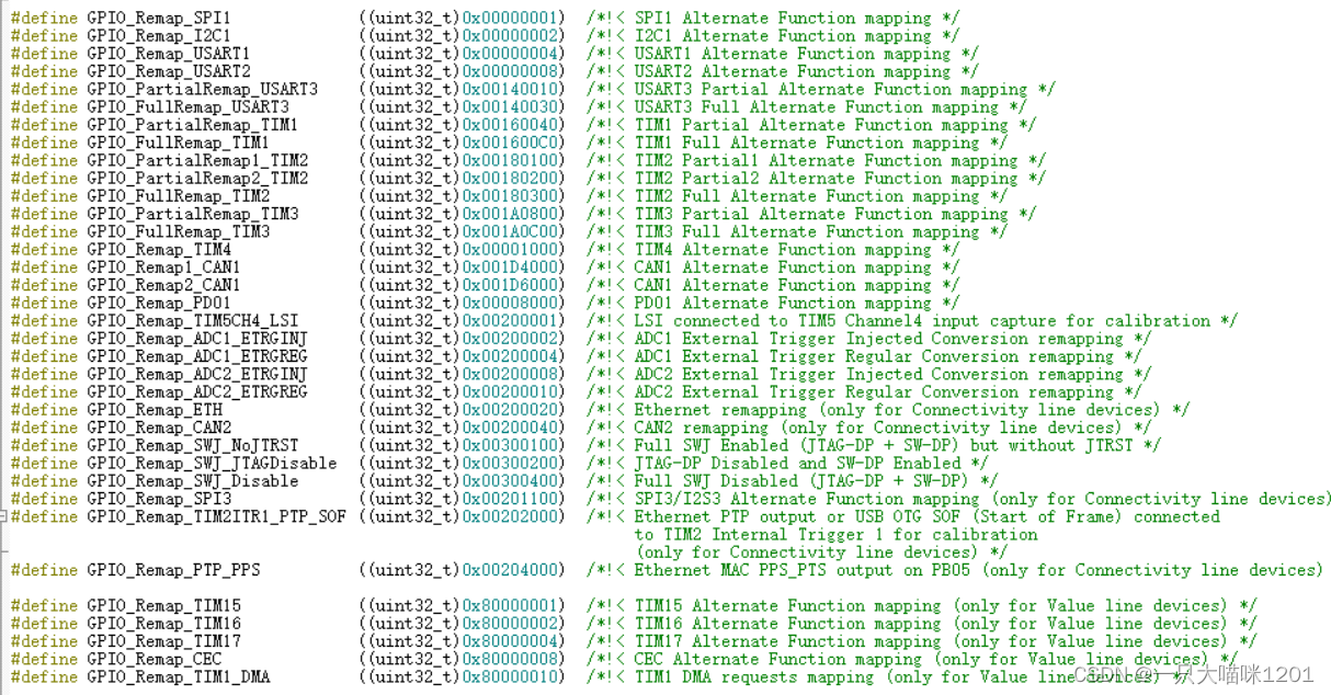
The first parameter of this function has many , As shown in the above figure , Pass the parameters representing the peripherals corresponding to the re image and the re image mode to the start re image function .
GPIO_PinRemapConfig(GPIO_PartialRemap_USART3,ENABLE);// Partial remapping
GPIO_PinRemapConfig(GPIO_FullRemap_USART3,ENABLE);// Complete remapping
The second parameter only ENABLE and DISABLE, That is, decide whether to enable the re image .
After the above 4 Step by step, you will succeed USART3 Some ports of are remapped to PC10 To PC12, Or all ports are remapped to PD8 To PD12 On .
summary
Whether it is port multiplexing or port re imaging , All for the purpose of using the built-in peripherals of the chip , Only through port multiplexing or re imaging GPIO To connect with built-in peripherals , Deliver information to peripherals . Generally, port multiplexing is enough for us .
边栏推荐
- Ppt template and material download website (pure dry goods, recommended Collection)
- LED模拟与数字调光
- Hard core sharing: a common toolkit for hardware engineers
- 2022-06-30 Unity核心8——模型导入
- 模拟卷Leetcode【普通】1557. 可以到达所有点的最少点数目
- 【istio简介、架构、组件】
- OpenGL 3D graphics rendering
- 测试人一定要会的技能:selenium的三种等待方式解读,清晰明了
- 串口实验——简单数据收发
- Screen automatically generates database documents
猜你喜欢

The longest ascending subsequence model acwing 1017 Strange thief Kidd's glider
【istio简介、架构、组件】
E-commerce campaign Guide
【Istio Network CRD VirtualService、Envoyfilter】
LED模拟与数字调光
How to realize sliding operation component in fast application
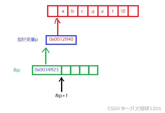
C语言指针(习题篇)
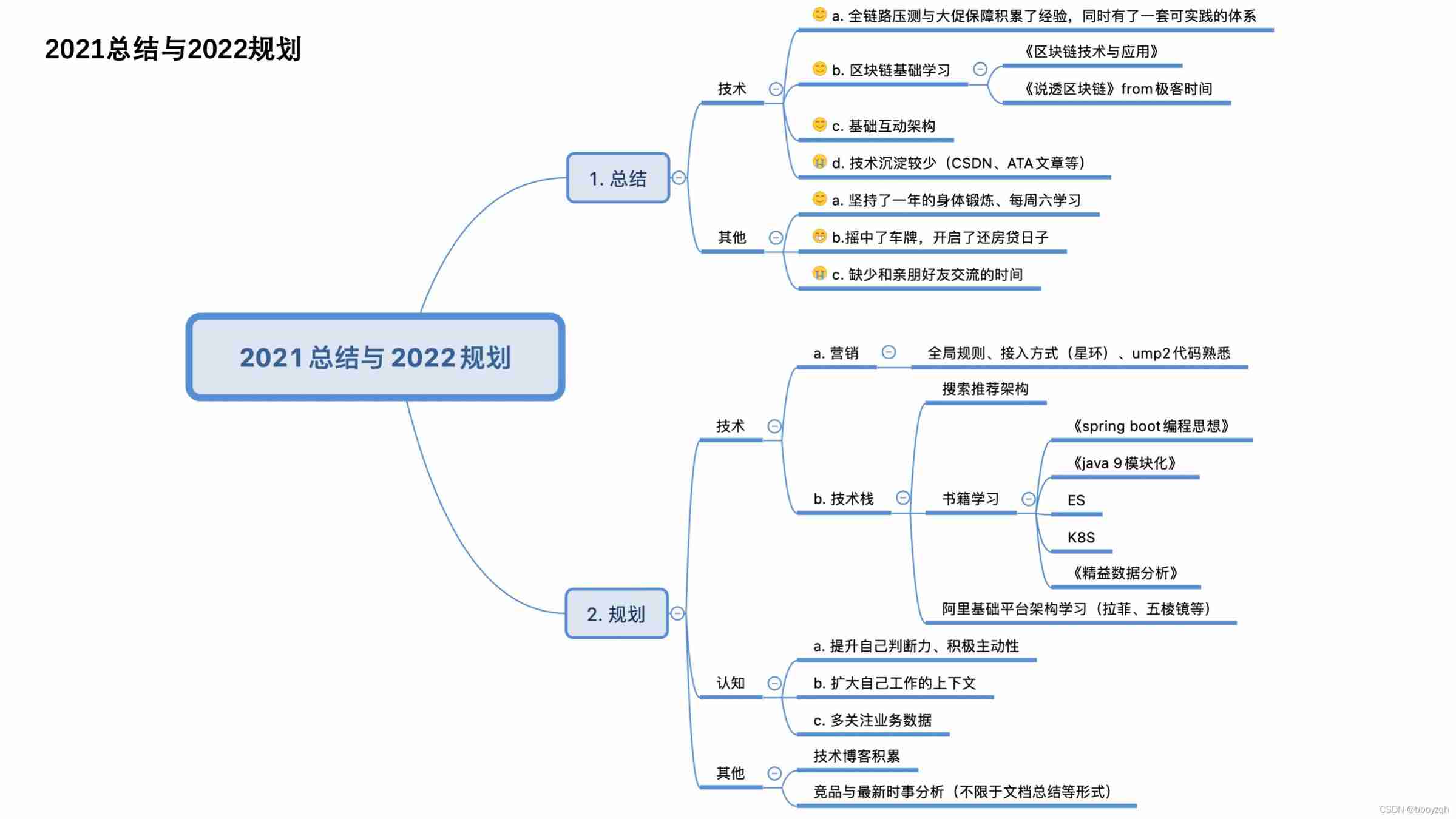
2021 year end summary
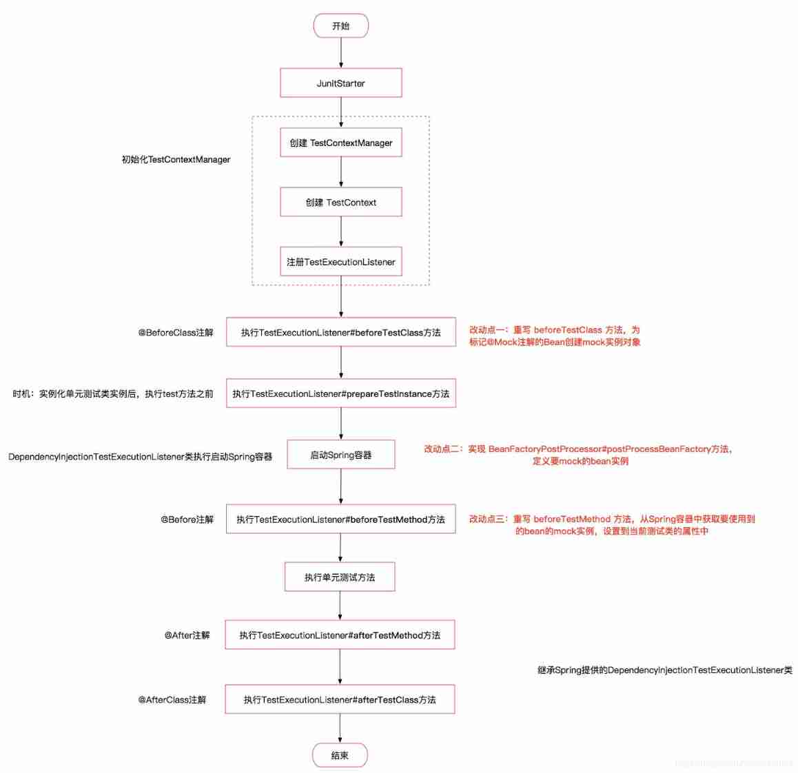
Two schemes of unit test

Do you have any certificates with high gold content?
随机推荐
Count the number of words in the string c language
Esp32-ulp coprocessor low power mode RTC GPIO interrupt wake up
Mountaineering team (DFS)
【ChaosBlade:节点 CPU 负载、节点网络延迟、节点网络丢包、节点域名访问异常】
Tronapi wave field interface - source code without encryption - can be opened twice - interface document attached - package based on thinkphp5 - detailed guidance of the author - July 6, 2022 - Novice
串口實驗——簡單數據收發
平台化,强链补链的一个支点
JVM 垃圾回收 详细学习笔记(二)
Markdown editor Use of MD plug-in
[MySQL] detailed explanation of trigger content of database advanced
硬件大熊原创合集(2022/06更新)
Newly found yii2 excel processing plug-in
Lenovo hybrid cloud Lenovo xcloud: 4 major product lines +it service portal
Screen automatically generates database documents
With an annual salary of 50W, Alibaba P8 will come out in person to teach you how to advance from testing
Reading notes of pyramid principle
PPT模板、素材下载网站(纯干货,建议收藏)
RuntimeError: Calculated padded input size per channel: (1 x 1). Kernel size: (5 x 5). Kernel size c
Simulation volume leetcode [general] 1567 Length of the longest subarray whose product is a positive number
systemd