当前位置:网站首页>STM32 GPIO LED and buzzer implementation [Day 4]
STM32 GPIO LED and buzzer implementation [Day 4]
2022-08-03 16:09:00 【Red Hat White Hat】
STM32 GPIO LED实现
原理图
General register
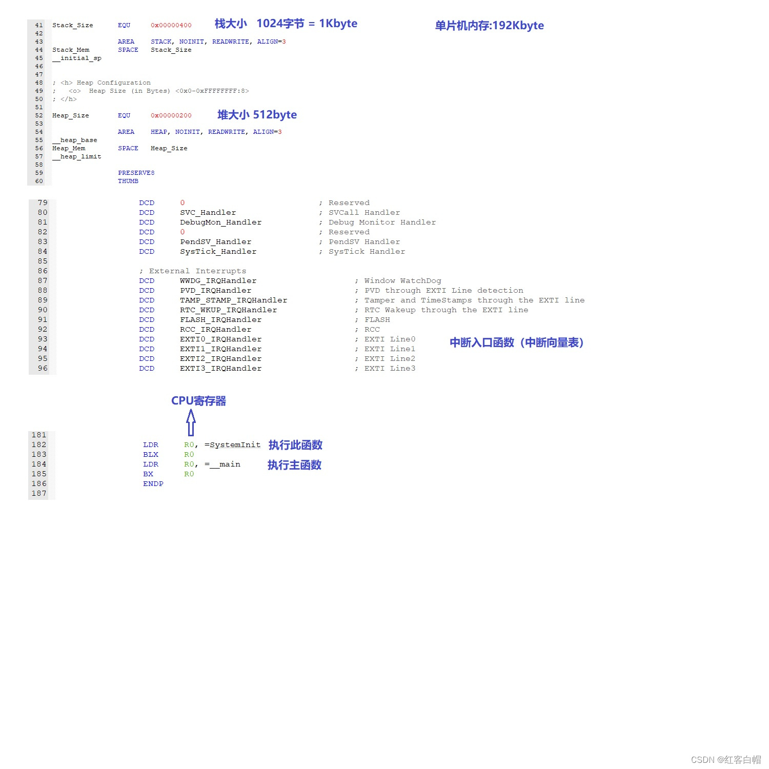
启动 汇编
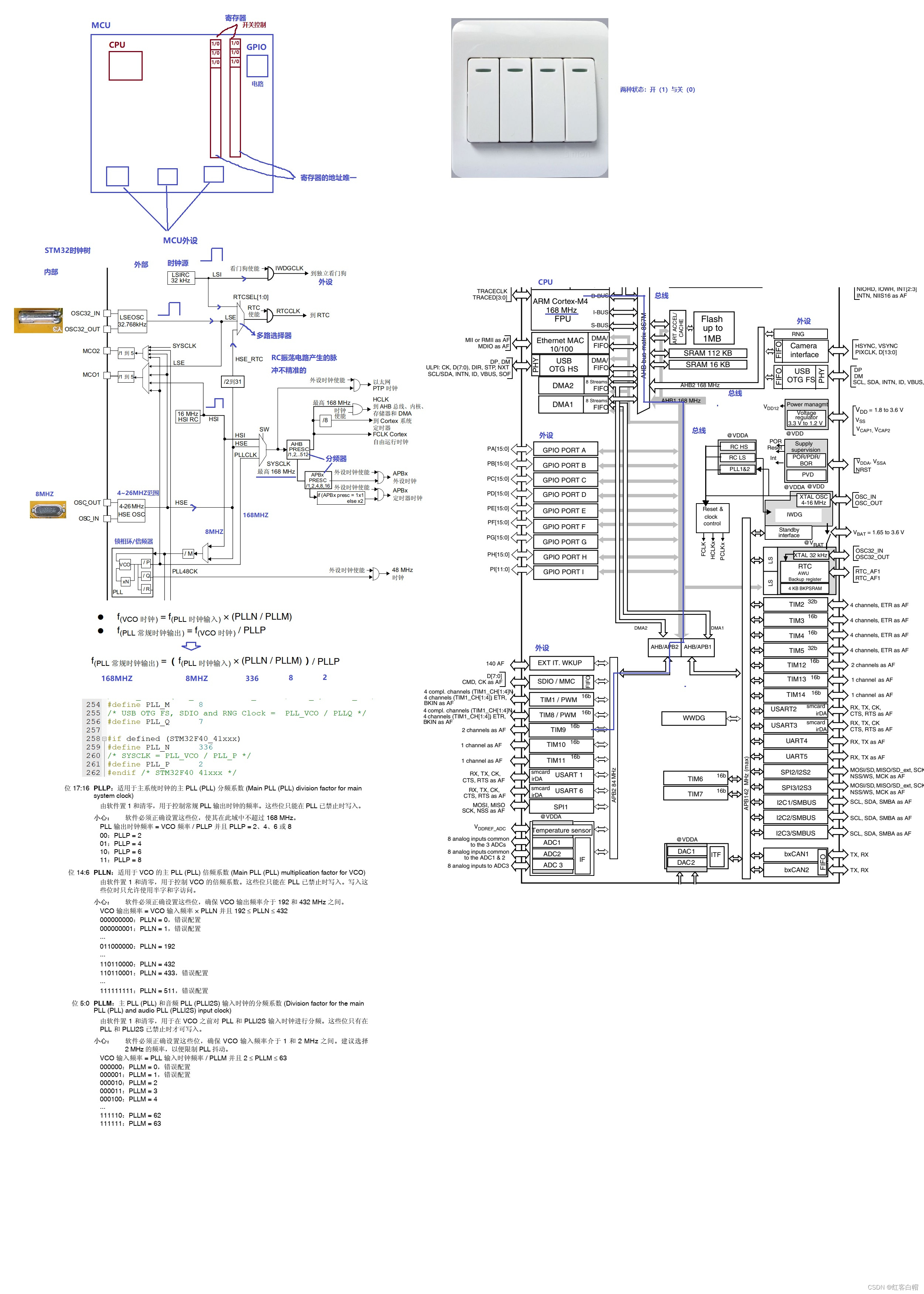
时钟树
一 、STM32大小说明
栈大小:1024Kbyte
堆大小:512byte
单片机内存:192Kbyte CPU -> 寄存器->R0 =systemInit :初始化函数(配置) ->main执行主函数
二、STM32时钟分析
寄存器:寄存器的功能是存储二进制代码,它是由具有存储功能的触发器组合起来构成的.一个触发器可以存储1位二进制代码,故存放n位二进制代码的寄存器,需用n个触发器来构成 在计算机领域,寄存器是CPU内部的元件,包括通用寄存器、专用寄存器和控制寄存器.寄存器拥有非常高的读写速度,所以在寄存器之间的数据传送非常快.
MCU: 微控制单元(MCU) ,又称单片微型计算机或者单片机,是把中央处理器(CPU)的频率与规格做适当缩减,并将
内存(memory)、计数器(Timer)、 USB、A/D转换、UART(通用异步收发传输器)、PLC(可编程逻辑控制器)、 DMA(直接内存访问)等周边接口,甚至LCD驱动电路All integrated on a single chip,形成芯片级的计算机,为不同的应用场合做不同组合控制.
控制寄存器:Quite a row can be0/1Set the switch function of the peripheral,In the program to the corresponding register via the address,So the control register address is the only.
芯片时钟:芯片工作时,Is the need for pulse,Pulse equivalent to chip start up,Can guarantee the normal work of the chip,类似于人,Normal heart beat,Human life can be normal.
1HZ:A second produce1个脉冲
Frequency conversion unit:
1GHZ =  1000MHZ = 1000 000KHZ = 1000 000 000HZ
STM32时钟源: The clock source is can produce device.
LSIRC    32KHZ    		32 kHz 低速内部 RC (LSIRC)
LSEOSC  32.168KHZ		32.768 kHz 低速外部晶振( LSE 晶振)
HSIRC	 16MHZ		   16MHZ  高速内部 RC (LSIRC)
HSEOSC 4-26MHZ       4-26MHZ高速外部晶振(HSE 晶振)
Guangdong embedded development board external crystals as8MHZ
STM32The main bus clock frequency
SYSCLK					168MHZ
HCLK					   168MHZ
AHB1/AHB2				168MHZ
APB1					   42MHZ
APB2					   84MHZ
三、GPIO分析
GPIO: GPIO(英语:General-purpose input/output),通用型之输入输出) GPIO分组
STM32F407ZET6(芯片型号)
    -  一共有7组IO口(PA  PB  PC  PD  PE  PF  PG)
    -  每组IO口有16个IO引脚
    -  一共16X7=112个IO引脚
外加2个PH0和PH1
一共114个IO口引脚(I:input  O:output)       IO引脚口:114
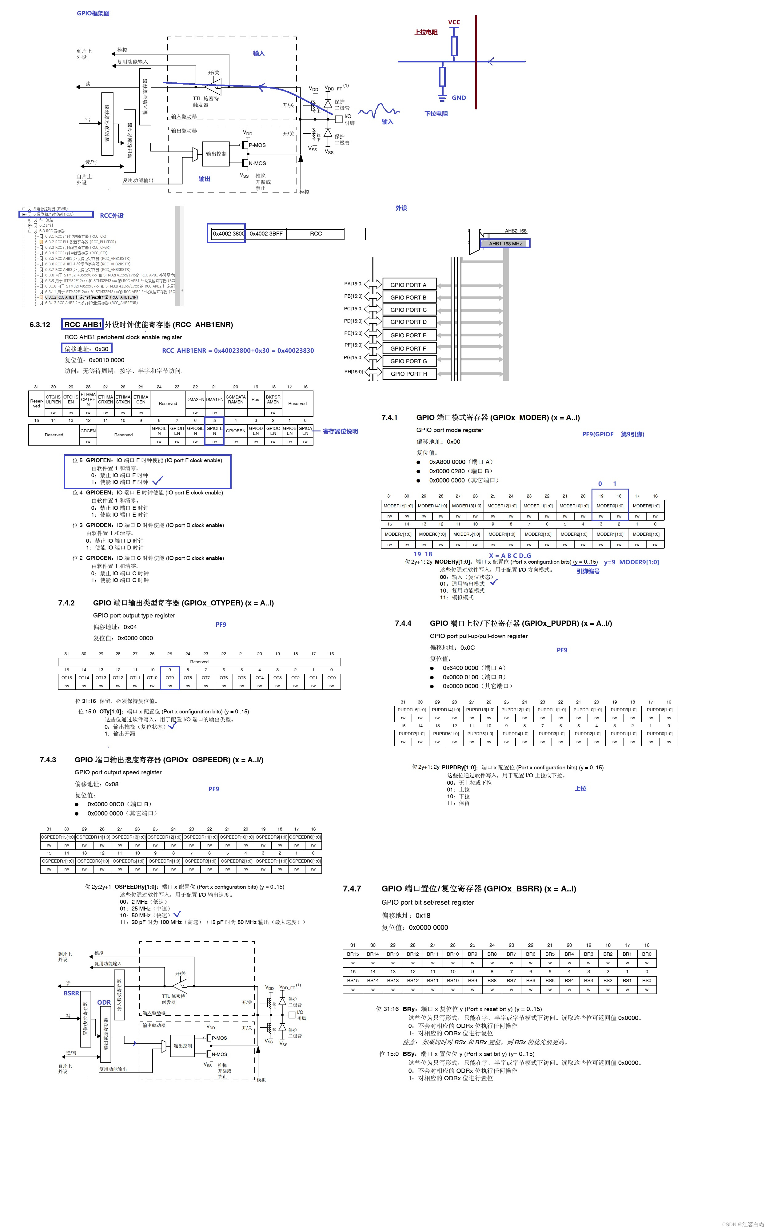
每组(PA PB PC PD PE PF PG)通用 I/O 端口包括:
•4 个 32 位配置寄存器(GPIOx_MODER、GPIOx_OTYPER、GPIOx_OSPEEDR 和 GPIOx_PUPDR).
•2 个 32 位数据寄存器(GPIOx_IDR 和 GPIOx_ODR).
•1 个 32 位置位/复位寄存器 (GPIOx_BSRR)、
•1 个 32 位锁定寄存器(GPIOx_LCKR)
•2 个 32 位复用功能选择寄存器(GPIOx_AFRH 和 GPIOx_AFRL).(高 低)
GPIO工作方式(寄存器设置GPIO工作方式)
4种输入模式
`浮空输入(No pull up and down the resistance) 上拉输入(有上拉电阻) 下拉输入(有下拉电阻) 模拟输入`
4种输出模式
`开漏输出(带上拉或者下拉) 开漏复用功能(带上拉或者下拉) 推挽式输出(带上拉或者下拉) Push-pull is reusable function(带上拉或者下拉)`
4种最大输出速度
`2MHZ 25MHZ 50MHZ 100MHZ`
1.注意点
开漏输出只能输出0(低电平),If the output1(高电平),需要外部接上拉电阻(类似到51单片机P0组).
Push-pull output can be output0(低电平)或者1(高电平),This is a common pattern
四、寄存器地址查找
寄存器地址 = Base address register group+偏移地址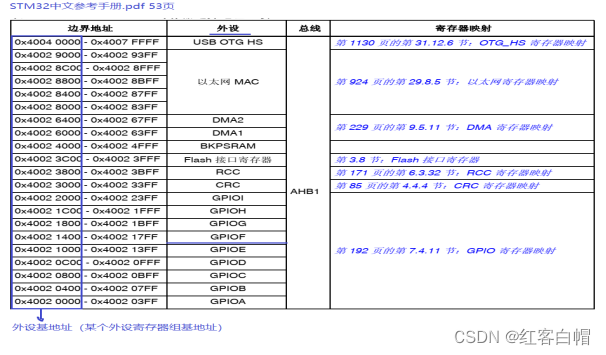
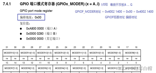
1、写出GPIOFPeripherals all register address
GPIOF_MODER    =  0x42001400 + 0x00 = 0x40021400
GPIOF_OTYPER    =  0x42001400 + 0x04 = 0x40021404
GPIOF_OSPEEDR  =  0x42001400 + 0x08 = 0x40021408
GPIOF_PUPDR 	  =  0x42001400 + 0x0C = 0x4002140C
GPIOF_IDR 	      =  0x42001400 + 0x10 = 0x40021410
GPIOF_ODR 	  =  0x42001400 + 0x14 = 0x40021414
GPIOF_BSRR 	  =  0x42001400 + 0x18 = 0x40021418
GPIOF_LCKR 	  =  0x42001400 + 0x1C = 0x4002141C
GPIOF_AFRL 	  =  0x42001400 + 0x20 = 0x40021420
GPIOF_AFRH 	  =  0x42001400 + 0x24 = 0x4002142C
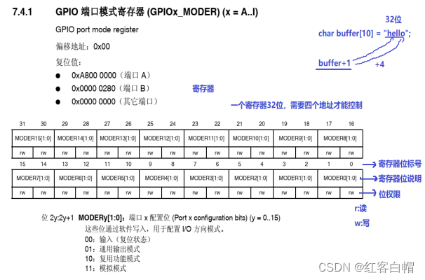
五、LEDLamp development
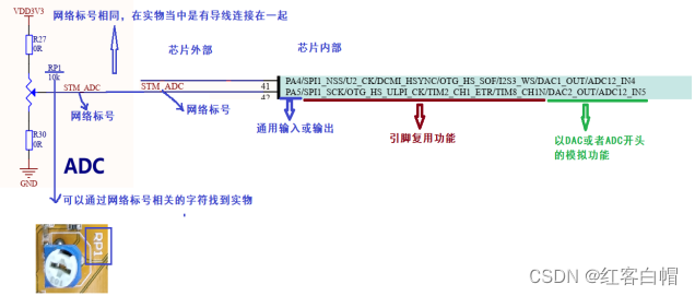
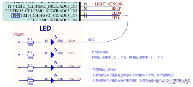
1、理解led灯原理图
LED0连接在PF9
PF9输出低电平(0), 灯亮;
PF9输出高电平(1),灯灭;
2、打开GPIOF组时钟
//将第5位置1 使能GPIOF组时钟 RCC_AHB1ENR |= (0x01<<5);
设置PF9灯为输出模式 Push-pull output on the pull speed(50MHZ)
4、通过GPIOF_BSRR控制LEDThe light with out
举例:
① Register to realize functionlcd.h RCC_AHB1ENR
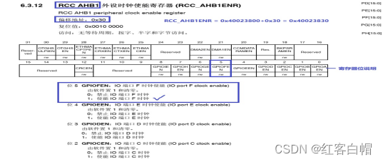
5.设置时钟
#define RCC_AHB1ENR (*((unsigned int *)(0x40023800+0x30)))
//Value types to address,Through reference address solution,The value of access address space
设置端口模式 2y+1:2y y=寄存器的PFy
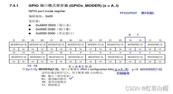
#define GPIOF_MODER (*((unsigned int *)(0x40021400+0x00)))
//Value types to address,Through reference address solution,The value of access address space //The board lamp:D1 D2
#define GPIOE_MODER (*((unsigned int *)(0x40021000+0x00)))
 //Value types to address,Through reference address solution,The value of access address space //The board lamp:D3 D4
6.设置输出类型
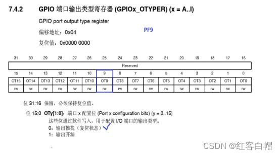
#define GPIOF_OTYPER (*((unsigned int *)(0x40021400+0x04)))
 //Value types to address,Through reference address solution,The value of access address space
#define GPIOE_OTYPER (*((unsigned int *)(0x40021000+0x04)))
//Value types to address,Through reference address solution,The value of access address space
设置端口速度 2y:2y+1 y=To configure the operation a
#define GPIOF_OSPEEDR (*((unsigned int *)(0x40021400+0x08)))
 //Value types to address,Through reference address solution,The value of access address space
#define GPIOE_OSPEEDR (*((unsigned int *)(0x40021000+0x08)))
 //Value types to address,Through reference address solution,The value of access address space
7.设置上拉电阻
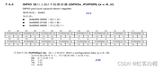
#define GPIOF_PUPDR (*((unsigned int *)(0x40021400+0x0C)))
//Value types to address,Through reference address solution,The value of access address space
#define GPIOE_PUPDR (*((unsigned int *)(0x40021000+0x0C)))
//Value types to address,Through reference address solution,The value of access address space

GPIOF_BSRR设置输出控制
#define GPIOF_ODR (*((unsigned int *)(0x40021400+0x14))) //Value types to address,Through reference address solution,The value of access address space
#define GPIOE_ODR (*((unsigned int *)(0x40021000+0x14))) //Value types to address,Through reference address solution,The value of access address space
GPIOF_BSRR设置控制位 The light and buzzer
#define GPIOF_BSRR (*((unsigned int *)(0x40021400+0x18))) //Value types to address,Through reference address solution,The value of access address space
#define GPIOE_BSRR (*((unsigned int *)(0x40021000+0x18))) //Value types to address,Through reference address solution,The value of access address space
举例
#ifndef __LED_H
#define __LED_H

#include "stm32f4xx.h"
//设置时钟
#define RCC_AHB1ENR (*((unsigned int *)(0x40023800+0x30))) //Value types to address,Through reference address solution,The value of access address space

#define GPIOF_MODER (*((unsigned int *)(0x40021400+0x00))) //Value types to address,Through reference address solution,The value of access address space
#define GPIOF_OTYPER (*((unsigned int *)(0x40021400+0x04))) //Value types to address,Through reference address solution,The value of access address space
#define GPIOF_OSPEEDR (*((unsigned int *)(0x40021400+0x08))) //Value types to address,Through reference address solution,The value of access address space
#define GPIOF_PUPDR (*((unsigned int *)(0x40021400+0x0C))) //Value types to address,Through reference address solution,The value of access address space
#define GPIOF_ODR (*((unsigned int *)(0x40021400+0x14))) //Value types to address,Through reference address solution,The value of access address space
#define GPIOF_BSRR (*((unsigned int *)(0x40021400+0x18))) //Value types to address,Through reference address solution,The value of access address space

#define GPIOE_MODER (*((unsigned int *)(0x40021000+0x00))) //Value types to address,Through reference address solution,The value of access address space
#define GPIOE_OTYPER (*((unsigned int *)(0x40021000+0x04))) //Value types to address,Through reference address solution,The value of access address space
#define GPIOE_OSPEEDR (*((unsigned int *)(0x40021000+0x08))) //Value types to address,Through reference address solution,The value of access address space
#define GPIOE_PUPDR (*((unsigned int *)(0x40021000+0x0C))) //Value types to address,Through reference address solution,The value of access address space
#define GPIOE_ODR (*((unsigned int *)(0x40021000+0x14))) //Value types to address,Through reference address solution,The value of access address space
#define GPIOE_BSRR (*((unsigned int *)(0x40021000+0x18))) //Value types to address,Through reference address solution,The value of access address space

void Led_Init(void);

//Initialize allD1 -- D4The lamp of the function
void Led0(void);
void Led1(void);
void Led2(void);
void Led3(void);
void Beep(void);  //蜂鸣器

#endif
② Register to realize functionlcd.c
void Led0()   //针对D1 D2灯 GPIOF_XXXX形式
{

	//设置GPIOF9为输出模式
	GPIOF_MODER &= ~(0x01<<19);	  //19位清0
	GPIOF_MODER |= (0x01<<18);	  //18位置1

	//设置GPIOF9For the output push-pull
	GPIOF_OTYPER &= ~(0x01<<9);  	//9位清0

	//设置GPIOF9为上拉
	GPIOF_PUPDR &= ~(0x01<<19);  	//19位清0
	GPIOF_PUPDR |= (0x01<<18);	  //18位置1

	//设置GPIOF9输出速度50MHZ
	GPIOF_OSPEEDR |= (0x01<<19);	//19位置1
	GPIOF_OSPEEDR &= ~(0x01<<18);	//18位清0
}
//***************************************************************************************
void Led2()  //针对D1 D2灯 GPIOE_XXXX形式
{


	//设置GPIOF13为输出模式
	GPIOE_MODER &= ~(0x01<<27);		 //27位清0
	GPIOE_MODER |= (0x01<<26);		 //26位置1

	//设置GPIOE输出速度为50MHZ
	GPIOE_OSPEEDR |= (0x01<<26);   //26位置1
	GPIOE_OSPEEDR &= ~(0x01<<27);  //27为清0

	//设置GPIOE为上拉
	GPIOE_PUPDR &= ~(0x01<<27);    //27位清0
	GPIOE_PUPDR |= (0x01<<26);		 //26位置1

	//设置GPIOEFor the output push-pull
	GPIOE_OTYPER &= ~(0x01<<13); 	 //13位清0
}
解释:模式 速度 上拉 Operation of the corresponding bit
D1(19 - 18位) D2 (21 -20):设置相关参数
D3(27 - 26位) D4 (29 -28):设置相关参数
解释:推挽 GPIOF_OTYPER Operation of the corresponding bit0
D1(9位清0) D2 (10位清0)
D3(13位清0) D4 (14位清0)
③ Register to realize functionmain.c GPIOX_BSRR->ODR
板子:D1 --D2灯 GPIOF_BSRR
` BSRR 25位置1 ODR输出0 Led0灯亮 D1亮 BSRR 9位置1 ODR输出1 Led0灯灭 D1灭 BSRR 26位置1 ODR输出0 Led1灯亮 D2亮 BSRR 10位置1 ODR输出1 Led1灯灭 D2灭 `
板子:D3 --D4灯 GPIOE_BSRR
` BSRR 29位置1 ODR输出0 Led2灯亮 D3亮 BSRR 13位置1 ODR输出1 Led2灯灭 D3灭 BSRR 30位置1 ODR输出0 Led3灯亮 D4亮 BSRR 14位置1 ODR输出1 Led3灯灭 D4灭 `
六、蜂鸣器
As one of the buzzer control 复位和置位BSRR
` //BSRR 24位置1 ODR输出0 蜂鸣器关 GPIOE_BSRR |= (0x01<<24); //BSRR 8位置1 ODR输出1 蜂鸣器开 GPIOE_BSRR |= (0x01<<8); `
七、问题上、Pulldown resistor function
> 1、Please explain、Pulldown resistor function
上拉就是将不确定的信号通过一个电阻钳位在高电平,电阻同时起限流作用.【灌电流】
1、当TTL电路驱动CMOS电路时,If the circuit output high level belowCMOS电路的最低高电平(一般为3.5V),
这时就需要在TTL的输出端接上拉电阻,以提高输出高电平的值.U=IR 2、OCGate pull up resistors must be used,以提高输出的高电平值.
3、In order to enhance the driving ability of the output pin,有的单片机管脚上也常使用上拉电阻.
4、在CMOS芯片上,为了防止静电造成损坏,不用的管脚不能悬空,Generally to pull resistance to reduce the input impedance, 提供泄荷通路.
5、芯片的管脚加上拉电阻来提高输出电平,从而提高芯片输入信号的噪声容限,增强抗干扰能力.
6、提高总线的抗电磁干扰能力,管脚悬空就比较容易接受外界的电磁干扰.
7、长线传输中电阻不匹配容易引起反射波干扰,加上、Pulldown resistor is the resistance matching,有效的抑制反射波干扰.
Pulldown resistor is directly to the ground,When I answer the diode resistance is low level at the end.【拉电流】
1、提高电压准位 同时管脚悬空就比较容易接受外界的电磁干扰.
2、电阻匹配,抑制反射波干扰:长线传输中电阻不匹配容易引起反射波干扰,加上Pulldown resistor is the resistance matching,有效的抑制反射波干扰.
3、预设空间状态/缺省电位:在一些 CMOS 输入端接上或下拉电阻是为了预设缺省电位. 当你不用这些引脚的时候, 这些输入端下拉接 0
或上拉接 1.在I2C总线等总线上,空闲时的状态是由上下拉电阻获得
4、提高芯片输入信号的噪声容限:输入端如果是高阻状态,或者高阻抗输入端处于悬空状态,此时需要加上拉或下拉,以免收到随机电平而影响电路工作.
七、流水灯代码
MAIN.C
#include "stm32f4xx.h"
#include "led.h"
void delay(int n)
{

	int i,j;

	for(i=0; i<n; i++)
		for(j=0; j<30000; j++);

}
int main(void)
{

	Led_Init(); //初始化led

	while(1)
	{

		//BSRR 25位置1 ODR输出0 Led0灯亮
		GPIOF_BSRR |= (0x01<<25);
		delay(1000);

		//BSRR 9位置1 ODR输出1 灯灭
		GPIOF_BSRR |= (0x01<<9);
		//delay(1000);

		//BSRR 26位置1 ODR输出0 Led1灯亮
		GPIOF_BSRR |= (0x01<<26);
		delay(1000);

		//BSRR 10位置1 ODR输出1 灯灭
		GPIOF_BSRR |= (0x01<<10);
		//delay(1000);

		//BSRR 29位置1 ODR输出0 Led2灯亮
		GPIOE_BSRR |= (0x01<<29);
		delay(1000);

		//BSRR 13位置1 ODR输出1 灯灭
		GPIOE_BSRR |= (0x01<<13);
		//delay(1000);

		//BSRR 30位置1 ODR输出0 Led3灯亮
		GPIOE_BSRR |= (0x01<<30);
		delay(1000);

		//BSRR 14位置1 ODR输出1 灯灭
		GPIOE_BSRR |= (0x01<<14);
		delay(1000);

	}

	return 0;
}
LED.H
#ifndef __LED_H
#define __LED_H

#include "stm32f4xx.h"

//设置时钟
#define RCC_AHB1ENR (*((unsigned int *)(0x40023800+0x30))) //Value types to address,Through reference address solution,The value of access address space

#define GPIOF_MODER (*((unsigned int *)(0x40021400+0x00))) //Value types to address,Through reference address solution,The value of access address space
#define GPIOF_OTYPER (*((unsigned int *)(0x40021400+0x04))) //Value types to address,Through reference address solution,The value of access address space
#define GPIOF_OSPEEDR (*((unsigned int *)(0x40021400+0x08))) //Value types to address,Through reference address solution,The value of access address space
#define GPIOF_PUPDR (*((unsigned int *)(0x40021400+0x0C))) //Value types to address,Through reference address solution,The value of access address space
#define GPIOF_ODR (*((unsigned int *)(0x40021400+0x14))) //Value types to address,Through reference address solution,The value of access address space
#define GPIOF_BSRR (*((unsigned int *)(0x40021400+0x18))) //Value types to address,Through reference address solution,The value of access address space

#define GPIOE_MODER (*((unsigned int *)(0x40021000+0x00))) //Value types to address,Through reference address solution,The value of access address space
#define GPIOE_OTYPER (*((unsigned int *)(0x40021000+0x04))) //Value types to address,Through reference address solution,The value of access address space
#define GPIOE_OSPEEDR (*((unsigned int *)(0x40021000+0x08))) //Value types to address,Through reference address solution,The value of access address space
#define GPIOE_PUPDR (*((unsigned int *)(0x40021000+0x0C))) //Value types to address,Through reference address solution,The value of access address space
#define GPIOE_ODR (*((unsigned int *)(0x40021000+0x14))) //Value types to address,Through reference address solution,The value of access address space
#define GPIOE_BSRR (*((unsigned int *)(0x40021000+0x18))) //Value types to address,Through reference address solution,The value of access address space

void Led_Init(void);

//Initialize allD1 -- D4The lamp of the function
void Led0(void);
void Led1(void);
void Led2(void);
void Led3(void);
//void Beep(void);

#endif
LED.C
#include "led.h"

void Led_Init(void)
{

	//将第5位置1 使能GPIOF组时钟
	RCC_AHB1ENR |= (0x01<<5);

	//将第4位置1 使能GPIOE组时钟
	RCC_AHB1ENR |= (0x01<<4);

	Led0();
	Led1();
	Led2();
	Led3();

}
/********************************* 引脚说明: LED0 -- PF9 **********************************/
void Led0()
{

	//设置GPIOF9为输出模式
	GPIOF_MODER &= ~(0x01<<19);	  //19位清0
	GPIOF_MODER |= (0x01<<18);	  //18位置1

	//设置GPIOF9For the output push-pull
	GPIOF_OTYPER &= ~(0x01<<9);  	//9位清0

	//设置GPIOF9为上拉
	GPIOF_PUPDR &= ~(0x01<<19);  	//19位清0
	GPIOF_PUPDR |= (0x01<<18);	  //18位置1

	//设置GPIOF9输出速度50MHZ
	GPIOF_OSPEEDR |= (0x01<<19);	//19位置1
	GPIOF_OSPEEDR &= ~(0x01<<18);	//18位清0
}
/********************************* 引脚说明: LED1 -- PF10 **********************************/
void Led1()
{

	//设置GPIOF10为输出模式
	GPIOF_MODER &= ~(0x01<<21);	  //21位清0
	GPIOF_MODER |= (0x01<<20);	  //20位置1

	//设置GPIOF9For the output push-pull
	GPIOF_OTYPER &= ~(0x01<<10);	//10位清0

	//设置GPIOF9为上拉
	GPIOF_PUPDR &= ~(0x01<<21);	  //21位清0
	GPIOF_PUPDR |= (0x01<<20);	  //20位置1

	//设置GPIOF9输出速度50MHZ
	GPIOF_OSPEEDR |= (0x01<<21);	//21位置1
	GPIOF_OSPEEDR &= ~(0x01<<20);	//20位清0
}
/********************************* 引脚说明: LED2 -- PE13 **********************************/
void Led2()
{

	//将第4位置1 使能GPIOE组时钟
	//RCC_AHB1ENR |= (0x01<<4);

	//设置GPIOF13为输出模式
	GPIOE_MODER &= ~(0x01<<27);		 //27位清0
	GPIOE_MODER |= (0x01<<26);		 //26位置1

	//设置GPIOE输出速度为50MHZ
	GPIOE_OSPEEDR |= (0x01<<26);   //26位置1
	GPIOE_OSPEEDR &= ~(0x01<<27);  //27为清0

	//设置GPIOE为上拉
	GPIOE_PUPDR &= ~(0x01<<27);    //27位清0
	GPIOE_PUPDR |= (0x01<<26);		 //26位置1

	//设置GPIOEFor the output push-pull
	GPIOE_OTYPER &= ~(0x01<<13); 	 //13位清0
}

/********************************* 引脚说明: LED3 -- PE14 **********************************/
void Led3()
{

	//设置GPIOE14为输出模式
	GPIOE_MODER &= ~(0x01<<29);	   //29位清0
	GPIOE_MODER |= (0x01<<28);	   //28位置1

	//设置GPIOE输出速度为50MHZ
	GPIOE_OSPEEDR |= (0x01<<28);   //28位置1
	GPIOE_OSPEEDR &= ~(0x01<<29);  //29为清0

	//设置GPIOE为上拉
	GPIOE_PUPDR &= ~(0x01<<29);    //29位清0
	GPIOE_PUPDR |= (0x01<<28);     //28位置1

	//设置GPIOEFor the output push-pull
	GPIOE_OTYPER &= ~(0x01<<14);   //14位清0
}
八、蜂鸣器代码
main.c
#include "stm32f4xx.h"
#include "led.h"

void delay(int n)
{

	int i,j;

	for(i=0; i<n; i++)
		for(j=0; j<30000; j++);

}
int main(void)
{

	Led_Init();
	while(1)
	{


		GPIOF_BSRR |= (0x01<<8);  //开
		delay(3000);
		GPIOF_BSRR |= (0x01<<24); //关

	}
	return 0;
}
Led.c
#ifndef __LED_H
#define __LED_H

#include "stm32f4xx.h"

//设置时钟
#define RCC_AHB1ENR (*((unsigned int *)(0x40023800+0x30))) //Value types to address,Through reference address solution,The value of access address space

#define GPIOF_MODER (*((unsigned int *)(0x40021400+0x00))) //Value types to address,Through reference address solution,The value of access address space
#define GPIOF_OTYPER (*((unsigned int *)(0x40021400+0x04))) //Value types to address,Through reference address solution,The value of access address space
#define GPIOF_OSPEEDR (*((unsigned int *)(0x40021400+0x08))) //Value types to address,Through reference address solution,The value of access address space
#define GPIOF_PUPDR (*((unsigned int *)(0x40021400+0x0C))) //Value types to address,Through reference address solution,The value of access address space
#define GPIOF_ODR (*((unsigned int *)(0x40021400+0x14))) //Value types to address,Through reference address solution,The value of access address space
#define GPIOF_BSRR (*((unsigned int *)(0x40021400+0x18))) //Value types to address,Through reference address solution,The value of access address space

#define GPIOE_MODER (*((unsigned int *)(0x40021000+0x00))) //Value types to address,Through reference address solution,The value of access address space
#define GPIOE_OTYPER (*((unsigned int *)(0x40021000+0x04))) //Value types to address,Through reference address solution,The value of access address space
#define GPIOE_OSPEEDR (*((unsigned int *)(0x40021000+0x08))) //Value types to address,Through reference address solution,The value of access address space
#define GPIOE_PUPDR (*((unsigned int *)(0x40021000+0x0C))) //Value types to address,Through reference address solution,The value of access address space
#define GPIOE_ODR (*((unsigned int *)(0x40021000+0x14))) //Value types to address,Through reference address solution,The value of access address space
#define GPIOE_BSRR (*((unsigned int *)(0x40021000+0x18))) //Value types to address,Through reference address solution,The value of access address space

void Led_Init(void);

//Initialize allD1 -- D4The lamp of the function
void Led0(void);
void Led1(void);
void Led2(void);
void Led3(void);
void Beep(void);

#endif
led.c
#include "led.h"

void Led_Init(void)
{

	//将第5位置1 使能GPIOF组时钟
	RCC_AHB1ENR |= (0x01<<5);

	//将第4位置1 使能GPIOE组时钟
	RCC_AHB1ENR |= (0x01<<4);

	Led0();
	Led1();
	Led2();
	Led3();
	Beep();

}
/********************************* 引脚说明: LED0 -- PF9 **********************************/
void Led0()
{

	//设置GPIOF9为输出模式
	GPIOF_MODER &= ~(0x01<<19);	  //19位清0
	GPIOF_MODER |= (0x01<<18);	  //18位置1

	//设置GPIOF9For the output push-pull
	GPIOF_OTYPER &= ~(0x01<<9);  	//9位清0

	//设置GPIOF9为上拉
	GPIOF_PUPDR &= ~(0x01<<19);  	//19位清0
	GPIOF_PUPDR |= (0x01<<18);	  //18位置1

	//设置GPIOF9输出速度50MHZ
	GPIOF_OSPEEDR |= (0x01<<19);	//19位置1
	GPIOF_OSPEEDR &= ~(0x01<<18);	//18位清0
}
/********************************* 引脚说明: LED1 -- PF10 **********************************/
void Led1()
{

	//设置GPIOF10为输出模式
	GPIOF_MODER &= ~(0x01<<21);	  //21位清0
	GPIOF_MODER |= (0x01<<20);	  //20位置1

	//设置GPIOF9For the output push-pull
	GPIOF_OTYPER &= ~(0x01<<10);	//10位清0

	//设置GPIOF9为上拉
	GPIOF_PUPDR &= ~(0x01<<21);	  //21位清0
	GPIOF_PUPDR |= (0x01<<20);	  //20位置1

	//设置GPIOF9输出速度50MHZ
	GPIOF_OSPEEDR |= (0x01<<21);	//21位置1
	GPIOF_OSPEEDR &= ~(0x01<<20);	//20位清0
}
/********************************* 引脚说明: LED2 -- PE13 **********************************/
void Led2()
{

	//将第4位置1 使能GPIOE组时钟
	//RCC_AHB1ENR |= (0x01<<4);

	//设置GPIOF13为输出模式
	GPIOE_MODER &= ~(0x01<<27);		 //27位清0
	GPIOE_MODER |= (0x01<<26);		 //26位置1

	//设置GPIOE输出速度为50MHZ
	GPIOE_OSPEEDR |= (0x01<<26);   //26位置1
	GPIOE_OSPEEDR &= ~(0x01<<27);  //27为清0

	//设置GPIOE为上拉
	GPIOE_PUPDR &= ~(0x01<<27);    //27位清0
	GPIOE_PUPDR |= (0x01<<26);		 //26位置1

	//设置GPIOEFor the output push-pull
	GPIOE_OTYPER &= ~(0x01<<13); 	 //13位清0
}

/********************************* 引脚说明: LED3 -- PE14 **********************************/
void Led3()
{

	//设置GPIOE14为输出模式
	GPIOE_MODER &= ~(0x01<<29);	   //29位清0
	GPIOE_MODER |= (0x01<<28);	   //28位置1

	//设置GPIOE输出速度为50MHZ 2y:2y 2*14:2*14+1 28:29
	GPIOE_OSPEEDR |= (0x01<<28);   //28位置1
	GPIOE_OSPEEDR &= ~(0x01<<29);  //29为清0

	//设置GPIOE为上拉
	GPIOE_PUPDR &= ~(0x01<<29);    //29位清0
	GPIOE_PUPDR |= (0x01<<28);     //28位置1

	//设置GPIOEFor the output push-pull
	GPIOE_OTYPER &= ~(0x01<<14);   //14位清0
}
//设置蜂鸣器
void Beep(void)
{

	//设置GPIOE8为01 输出模式
	GPIOF_MODER &= ~(0x01<<17);	   //0
	GPIOF_MODER |= (0x01<<16);	   //1

	//设置GPIOE输出速度为50MHZ
	GPIOF_OSPEEDR |= (0x01<<17);   //1
	GPIOF_OSPEEDR &= ~(0x01<<16);  //0

	//设置GPIOE为上拉
	GPIOF_PUPDR &= ~(0x01<<17);    //0
	GPIOF_PUPDR |= (0x01<<16);     //1

	//设置GPIOEFor the output push-pull
	GPIOF_OTYPER &= ~(0x01<<24);   //0


}
边栏推荐
猜你喜欢

Neural networks, cool?

红蓝对抗经验分享:CS免杀姿势
瞌睡检测系统介绍

一文看懂推荐系统:召回01:基于物品的协同过滤(ItemCF),item-based Collaboration Filter的核心思想与推荐过程

How to get the 2 d space prior to ViT?UMA & Hong Kong institute of technology & ali SP - ViT, study for visual Transformer 2 d space prior knowledge!.

Yii2安装遇到Loading composer repositories with package information

土耳其国防部:联合协调中心将对首艘乌克兰粮船进行安全检查
新一代网状网协议T-Mesh无线通信技术优势介绍

How to start an NFT collection
STM32 GPIO LED和蜂鸣器实现【第四天】
随机推荐
破解数字化转型困局,企业分析协同场景案例解析
扩展欧几里得求逆元实例
5v充8.4v1A电流充电管理ic
Taurus.MVC WebAPI 入门开发教程1:框架下载环境配置与运行(含系列目录)。
参与便有奖,《新程序员》杂志福利来袭!
爬虫注意
基于DMS的数仓智能运维服务,知多少?
Tolstoy: There are only two misfortunes in life
聊聊这个SaaS领域爆火的话题
兔起鹘落全端涵盖,Go lang1.18入门精炼教程,由白丁入鸿儒,全平台(Sublime 4)Go lang开发环境搭建EP00
leetcode:899. 有序队列【思维题】
瞌睡检测系统介绍
NodeJs - cross domain
spark入门学习-2
How much does Ark Survival Evolved cost?
JS basics--judgment
自定SvgIcon公用组件
Three key expectations for the crypto market in August Price moves north?Still expected to be in turmoil
STM32 GPIO LED和蜂鸣器实现【第四天】
JD6606SP5_JD6606SSP_JD6606SASP_JD6621W7百盛新纪元授权代理商
