当前位置:网站首页>[quick start of Digital IC Verification] 3. Introduction to the whole process of Digital IC Design
[quick start of Digital IC Verification] 3. Introduction to the whole process of Digital IC Design
2022-07-05 20:09:00 【luoganttcc】
Reading guide : The author has the honor to be a pioneer in the field of electronic information in China “ University of electronic technology ” During postgraduate study , Touch the cutting edge Numbers IC Verification knowledge , I heard something like Huawei Hisilicon 、 Tsinghua purple light 、 MediaTek technology And other top IC related enterprises in the industry , Pairs of numbers IC Verify some knowledge accumulation and learning experience . Want to get started for help IC Verified friends , After one or two thoughts , This column is specially opened , In order to spend the shortest time , Take the least detours , Most learned IC Verify technical knowledge .
List of articles
- One 、 Preface
- Two 、 Integrated circuit industry chain
- 3、 ... and 、 common SoC Chip architecture diagram
- Four 、 Numbers IC Design process
- 5、 ... and 、 Numbers IC Design specific indicators
- 6、 ... and 、 Based on standard units (STD CELL) Of ASIC Design process
- 7、 ... and 、Digital IC Design Flow( Summary )
- 8、 ... and 、 Numbers IC Design an overview of the whole process
- Nine 、 The front-end design is in-depth (RTL -> Netlist)
- Ten 、 The back-end design is in-depth (Netlist -> Layout)
- 11、 ... and 、VLSI Design process ( To sum up again )
- Twelve 、 Review
This section will introduce many IC Design process , Master and understand one !
One 、 Preface
Think of a sentence called “ No one can see Mount Tai ”, So if you want to have a comprehensive understanding of a thing , We must understand its overall appearance . Learning numbers IC Verification is the same , We need to know the numbers clearly IC Verify in numbers IC The position in the whole process of design !
In this section, we will learn the following aspects
- 1、 Numbers IC The design of the technological process ?
- 2、 Numbers IC Each stage of the design process is mainly What kind of work ?
- 3、 Numbers IC Every stage of the design process Main used EDA What are the tools ?
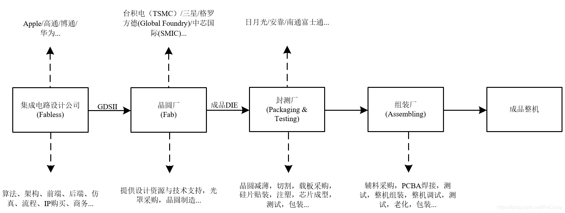
Two 、 Integrated circuit industry chain
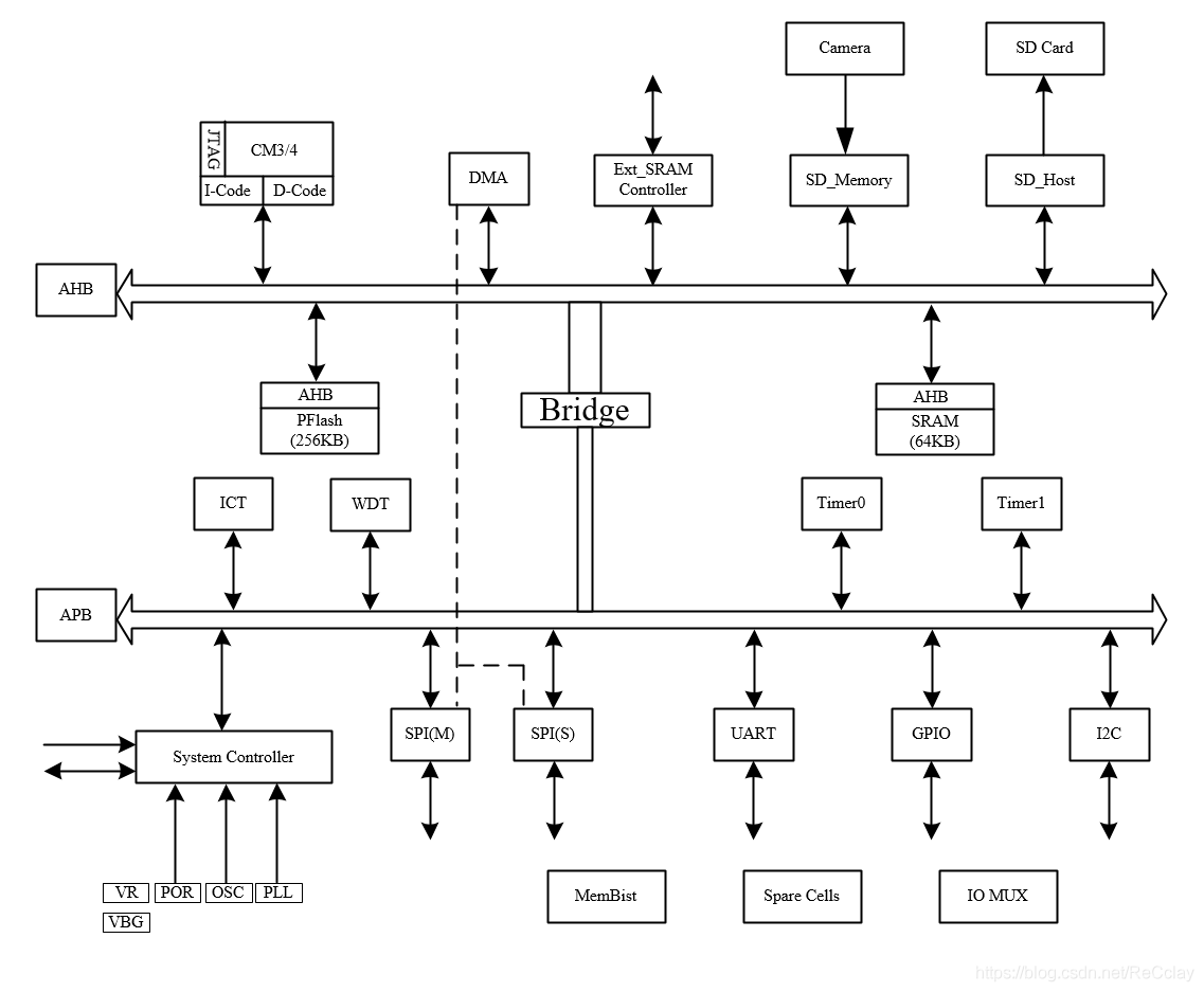
3、 ... and 、 common SoC chip framework chart
notes : There was a detailed introduction in last class :【 Numbers IC Verify the quick start 】2、 Through one SoC Project instance , understand SoC The architecture of , Explore the design process of digital system
SoC Chip composition , Four major parts :
- 1、 nucleus (CORE)
- 2、 Storage (MEM)
- 3、 peripherals (IO)
- 4、 Bus (BUS)
Four 、 Numbers IC Design process
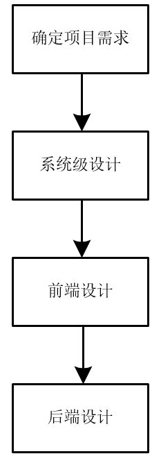
- 1、 Identify project requirements
- Determine the specific indicators of the chip : function 、 Power waste 、 performance 、IO Peripherals, etc
- Market demands , Research and development to assess needs
- 2、 System level design
- Use system modeling language to describe each module
- Completed by the system engineer
- 3、 Front end design 【 Logic 】
- RTL Design 、RTL Simulation (EDA Simulation verification )、 Hardware prototype verification (FPGA Hardware prototype verification )、 Circuit synthesis (RTL Code mapping (MAP) Form a gate level net list (STD CELL))
- 4、 Back end design 【 Physics 】
- Layout design 、 Physical verification 、 Post simulation, etc
5、 ... and 、 Numbers IC Design specific indicators
- 1、 Physical implementation
- Manufacturing process ( Foundry and process size )
- Die area (DIE size ,DIE By power consumption 、 cost 、 Numbers / Simulate the joint influence of area )
- encapsulation ( The larger the package , The better the heat dissipation , The higher the cost )
- 2、 Performance indicators
- Speed ( clock frequency )
- Power waste
- 3、 Functional indicators
- Function description
- Interface definition
6、 ... and 、 Based on standard units (STD CELL) Of ASIC Design process
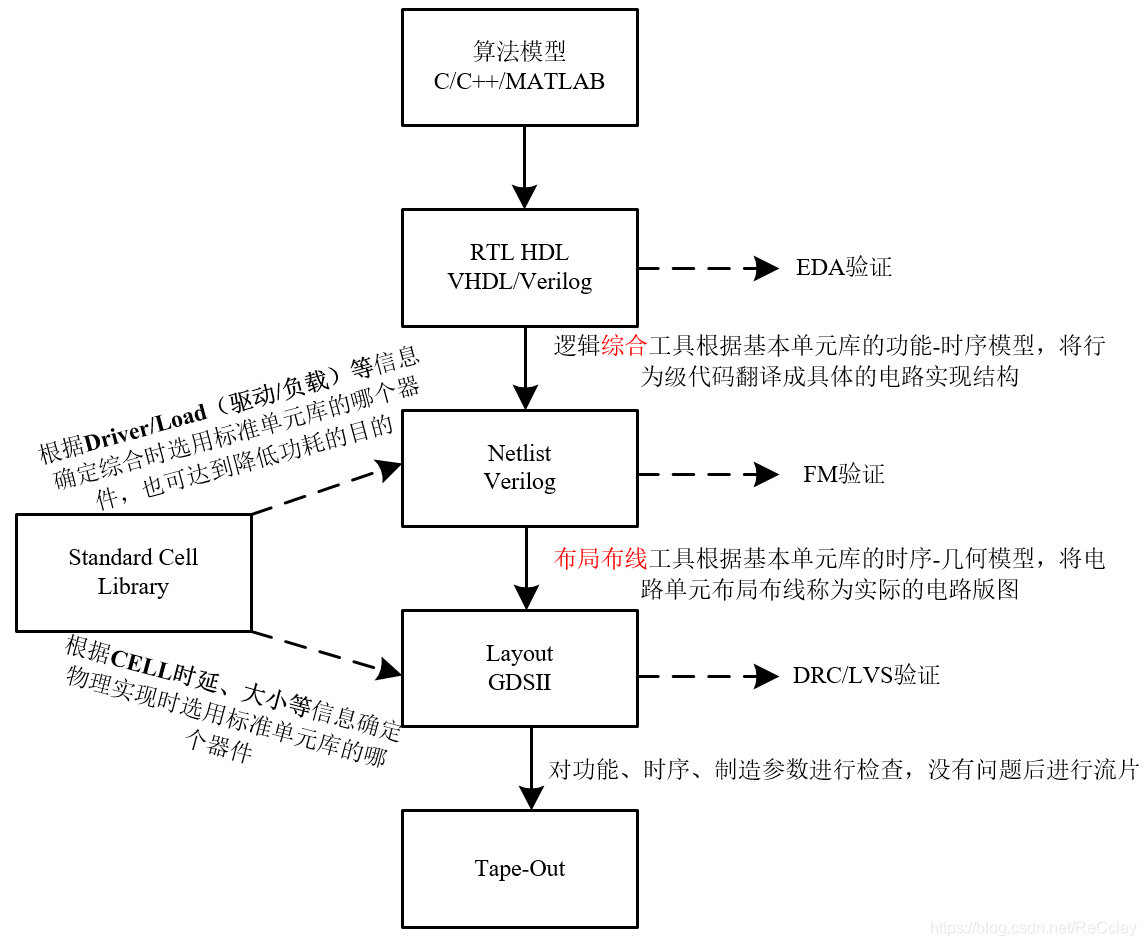
- Net watch : In electronic circuit design , Net watch (netlist) It is used to describe the connection between circuit elements , Generally speaking, it is a text file that follows some relatively simple markup syntax .
- GDSII Stream format : Common abbreviations GDSII, Is a database file format . It is used for data conversion of integrated circuit layout , And become a de facto industrial standard .GDSII It's a binary file , It contains the geometry of the plane in the integrated circuit layout , Text or label , And other relevant information, and can be composed of a hierarchy .GDSII The data can be used to reconstruct all or part of the layout information . It can be used to make lithography mask .
7、 ... and 、Digital IC Design Flow( Summary )
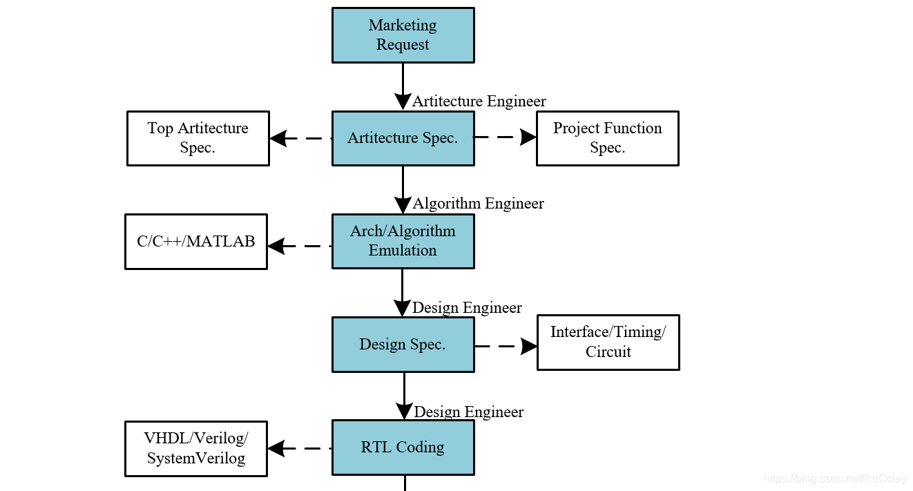
- 1、Marketing Request: The marketing personnel put forward the demand , R & D personnel participate in the discussion on the realizability of requirements , After all, some things are contradictory , Such as : Performance and power consumption , High performance is required , Low power consumption , This is obviously contradictory , It needs to be evaluated , Whether it can meet the expected requirements . After the needs are determined , It will be more complicated to change again , So at this stage, we must determine , The follow-up basically did not move !
- 2、Artitecture Spec.: After the needs are determined , Be able to write architecture documents , It consists of two parts : Overall architecture specification (Top Artitecture Spec.) And specific functional specifications (Project Function Spec.). among , The overall architecture specification refers to the modules , Such as :CPU、SRAM、DMA、AMBA etc. . Specific functional specifications refer to specific indicators , Such as :DMA How many channels does the module have 、 How many megabytes is the total clock frequency 、 There are several supported modes .
- This part is usually used by architecture engineers (Artitecture Engineer) complete , In some companies, they are also called system engineers (System Engineer, abbreviation SE). Such engineers are generally senior engineers .
- 3、Arch/Algorithm Emulation: After designing the architecture , You can do architecture / Simulation of Algorithm . The tools commonly used in this part are C/C++/MATLAB.
- This part is usually used by Algorithm Engineers (Algorithm Engineer) complete .
- 4、Design Spec.: Designing is not to write code when you get the algorithm at the beginning , But to make a design specification . Analogy building , We also need to plan the drawings before formally laying bricks . This part usually includes interface definition (Interface)、 Timing processing scheme (Timing)、 Key circuit drawing (Circuit).
- 5、RTL Coding: After the preparation of the design specifications in the previous part , You can program . Usually there are VHDL/Verilog/SystemVerilog Three programming languages are available !
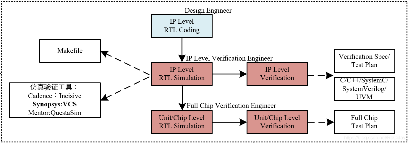
- Usually ,Design Spec and RTL Coding These two parts of work , It's all by Design Engineer A person completes ! about RTL Coding part , It can be subdivided into the following three parts , The relationship is shown in the figure below :【 The red part marked with bricks in the figure below is the position of the verification engineer !】
- ①、IP Level RTL Coding: First there are small IP, In order to have big SoC. The front is designed from top to bottom , First there is the architecture, then there are various modules . But the implementation is bottom-up , First there is the smallest IP Level code , Will integrate higher-level code .
- ②、IP Level RTL Simulation and IP Level Verification: Well designed IP Level After code , We can do simulation verification , Small IP Usually Design Engineer I made it on my own. , But when IP When I was older , There will be special verifiers to do ! In verification , We will use some scripts , Such as Makefile. Simulation tools used , There are three main EDA Manufacturer's :Cadence:Incisive;Synopsys:VCS;Mentor: QuestaSim. among VCS The most mainstream ,QuestaSim Used in small FPGA Development above , Because its function is not very powerful ! The languages used in the verification are :C/C++/SystemC/SystemVerilog/UVM several . When doing verification, I will also do verification Spec file , Figure out what points to check . The environment will be built after completion , Run case ! The core of verification is : Verify the completeness , So be clear IP Level Of this object module DUT, What are the function points to be tested , It has to be completely decomposed .【 Later, the verification engineer is also engaged in this work , Junior verification engineers usually do IP Level Verification】
- ③、Unit/Chip Level RTL Simulation and Unit/Chip Level
Verification: above IP Level After no problem , Synthesis of large modules Unit/Chip Level, Then do the verification ! The verification engineer of this part is generally called :Full Chip Verification Engineer, Need to work 4~5 It takes years for me to do !
- Usually ,Design Spec and RTL Coding These two parts of work , It's all by Design Engineer A person completes ! about RTL Coding part , It can be subdivided into the following three parts , The relationship is shown in the figure below :【 The red part marked with bricks in the figure below is the position of the verification engineer !】
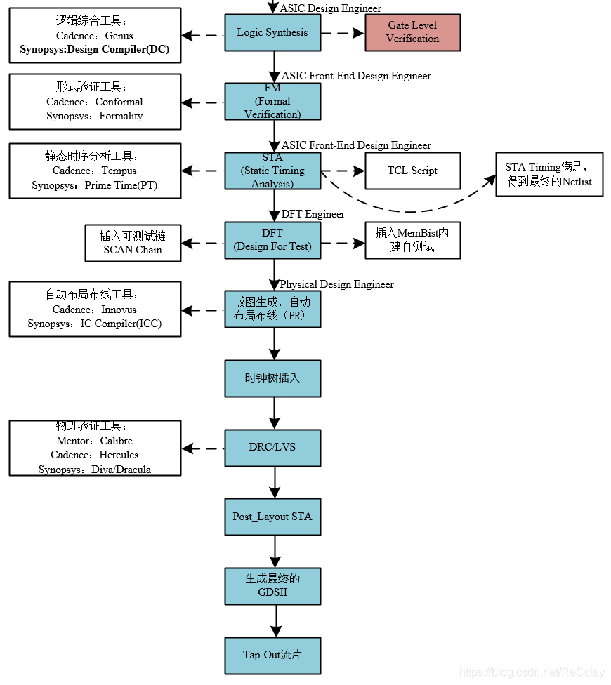
- 6、Logic Synthesis and Gate Level Verification:Coding After there is no problem with design and verification , At this time, it will be integrated , Will synthesize the net list . At the same time, it will also verify the gate level netlist , be called Gate Level Verification. At this stage, the main thing is to debug our verification environment , Prepare for the net list after the back-end physical implementation . At this stage, the net list contains less information , There are no physical parameters , It will run faster , Debugging will be more convenient . Net watch The verification of logical function correctness is through FM To guarantee , Not at all Gate Level Verification To guarantee , Special attention should be paid to this point ! About FM The following will also introduce . For integrated tools , The current mainstream is Synopsys:Design Compiler(DC).
- Logic synthesis is to realize the design RTL The code is mapped to a specific process library , Output into gate level netlist Netlist.【 according to Load、Driver Map process library …】
- Logical synthesis needs to be based on a specific synthesis library , In different libraries , Basic standard unit of gate circuit (Standard Cell) The area of , Timing parameters will be different !
- 7、Formal Verification: After logic synthesis and verification , Will be carried out in Formal verification , namely Formal Verification, Referred to as FM. Formal verification can also be called equivalence checking (Equivalence Check). Traverse all to “ Cone bottom ” A combination of points , If to “ Cone bottom ” A little 2 individual , So the combination has 4 individual :00 01 10 11. At this time, I will watch the door level net list “ Cone bottom ” The result is 4 Which one , and RTL The result is 4 Which of the results , Whether the comparison is the same , It is called formal verification ! Tools for formal verification include :Cadence:Conformal;Synopsys:Formality.
- Functionally (STA It's timing ) Verify the integrated netlist . The commonly used method is equivalence checking , After functional verification HDL Design for reference , Compare the integrated net list function , Whether they are functionally equivalent . This is to ensure that In the process of logical synthesis, the original HDL Describe the function of the circuit .
- 8、STA(Static Timing Analysis): In addition to logical equivalence, a comprehensive netlist , Still need to do static timing analysis ! The structure of the circuit is RTL Grade , There is combinatorial logic ( And or not ) And temporal logic (D trigger ) Two kinds of . For temporal logic, there are Setup/Hold( Set up time / keep ) requirement , The delay of combinational logic will affect these two parameters , It may cause too long delay , Cause violations . There are usually several solutions :①、 Put the combination logic with large delay CELL Replace the drive a little bigger , Let the delay decrease .②、 Insert temporal logic into combinatorial logic , That is, the way to add pipelines !
- Static time series analysis , This also belongs to the verification category , It mainly belongs to the verification category , It mainly verifies the circuit in time sequence , Check if there is a setup time in the circuit (Setup Time) And hold time (Hold Time) Violation of (Violation).
- STA And synthesis are usually implemented by script , The most commonly used scripts are TCL!
- STA Timing Satisfy , To get the final Netlist.
- 9、DFT(Design For Test):wafer In the process of making , Because of the deviation of process parameters , Cause incorrect function . At this time, there will be a DFT Design , For example, insert SCAN Chain, In this way, it can be stimulated by external irrigation , Connect all internal timing paths as a chain ! such as : External irrigation 1010, Compare the output sequence with the expected sequence , Verify the correctness , Find out whether there are manufacturing defects ! Of course, it can also be passed MemBist This built-in self-test , verification MEM Is there any defect , It goes with SCAN Chain equally , There is no need for external stimulation , Equivalent to the MEM The test circuit has been established on the periphery , its partner It can be generated by the test circuit , So it is called built-in self-test !DFT It is usually inserted on the basis of the net list !
- 10、 Layout generation , Automatic placement and routing (PR): After the above work is ok , It can be handed over to the back-end team for layout and wiring ! Such as :CELL In which position , One chip Usually put the simulation around , Put digital logic in the middle !
- 11、 Clock tree insert :STA It is an ideal clock network , To every D Trigger clk At the same time , But actually there are Wire Delay Of , Sometimes it will even be inserted at a distance buffer, So different positions D The phase of the trigger is different ! But when it comes to analysis , Different D trigger , Want to make Delay As consistent as possible , At this time, you need to insert the clock tree ( Insert buffer).
- 12、DRC/LVS(Design Route Check): Only one of the above will be done DRC Check , and LVS It is a comparison with the net list .
- 13、Post_Layout STA: At this time, the timing information is true , The clock 、CELL And so on, the timing information is true , The final STA, The final timing analysis !
- 14、 Generate the final GDSII
- 15、Tap-Out Tape-out
8、 ... and 、 Numbers IC Design an overview of the whole process
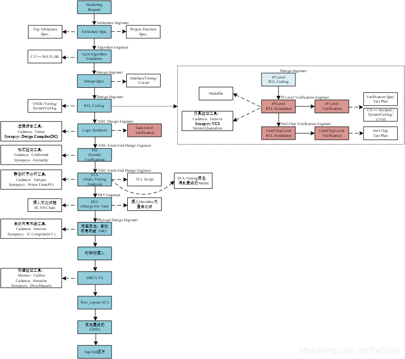
Nine 、 The front-end design is in-depth (RTL -> Netlist)
RTL -> Netlist:RTL Code to net list
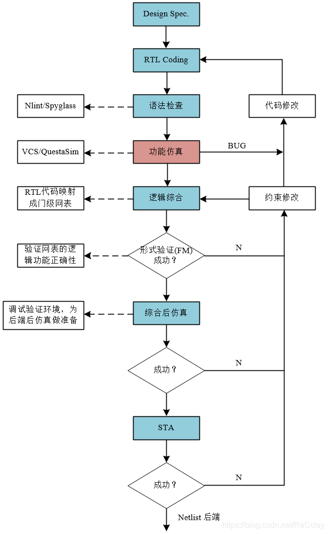
- Design Spec.: Write design documents
- RTL Coding: Write code
- RTL(Register Transfer Level) The design uses hardware description language , Such as VHDL/Verilog/SystemVerilog, The circuit is described based on the transmission between registers
- Syntax check : Besides grammar checking , And code style check , Make sure there is no problem with the syntax before the next simulation . Common tools are Nlint and Spyglass.
- Functional simulation ( Iterative process ): Use things like VCS/QuestaSim etc. EDA Tools , Write test cases , To verify whether the code meets expectations function . This function verification is the verification in the front end , It is different from that after the later chip comes back Manufacturing Verification (DFT verification ). Yes BUG( May be DUT Of bug, It may also be an authentication environment TB Of bug), Modify in iteration !
- Logic synthesis : After the basic functions of simulation are ok , Carry out logical synthesis , take RTL The description of is mapped into a gate level netlist .
- take RTL The program code obtained in the stage design is translated into various components of the actual circuit and the connection relationship between them , It can be represented by a table , It's called gate level netlist (Netlist)
- Formal verification (FM): The integrated net list and RTL Whether the function is equivalent ,
- Post synthesis simulation ( Iterative process ): Abbreviated as imitation , This step is not to verify the logical function of the netlist , This step is more about Debug the verification environment , Prepare for the post imitation of the back-end stage .( The back-end post imitation mainly imitates some power consumption data , The actual simulation at this time , The turnover rate is more real , At this time, the power consumption data is more real , To put it bluntly, just It is to prepare for imitating power consumption ) Of course, I'll take a look by the way at this time Netlist Are there some basic questions , Usually, this post imitation is a relatively simple system level (System Level) The use case , No IP Level Of , It is a high-level use case . There is a problem with the post imitation , It will also return to the modification script ( Constrain a path , Let the tool optimize better ) Or code ( Combinational logic delay modification , Let it meet our requirements )!
- STA(Staic Timing Analysis, Static time series analysis ): Apply a specific timing model (Timing Model), For specific circuit analysis and whether it violates the timing limit given by the designer (Timing Constraint).
- Verify the circuit in time sequence , Check if there is a setup time in the circuit (Setup Time) And hold time (Hold Time) Violation of (Violation).
Whole ASIC The design process is a iteration The process of , Cannot meet the requirements at any step , You need to repeat the previous steps , Even redesign RTL Code . The number of iterations of analog circuit design is even more !
Ten 、 The back-end design is in-depth (Netlist -> Layout)
Netlist -> Layout: Net list to layout
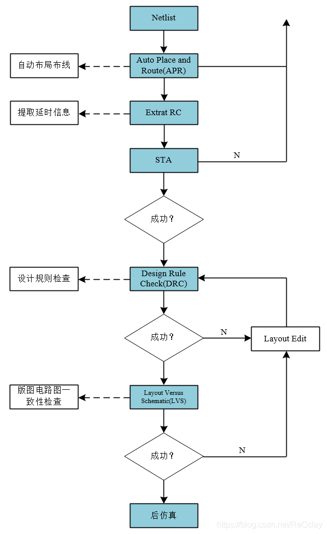
- Auto Place and Route(APR): Automatic placement and routing , This is done automatically by the tool , Especially in the current large-scale integrated circuits , In the context of hundreds of millions of doors of integration , It's certainly laborious and thankless to do it manually ! The tool is automatic Std Cell Place according to our limited area , Of course. PR when , We will Manual Put some Hard The unit is in the same Die On ( Large chips ), Do several hard cores together , Form multiple sub-chip. If chip It's too big , Tools are a little unbearable , So it is made into small hard unit , Take these small hard The units are integrated together . For one hard unit , Meeting Manual Put some MEM、 simulation IP, And place it on the side . The digital part is automatically laid out and placed around with tools . Of course, although it is automatic layout and wiring , If our design is not considerate , There will be Routing congestion (Congestion), At this time, you may also consider revising RTL, Insufficient tool wiring cloth , It may be that the density of the designed combinatorial logic is too high , There may also be some problems in the circuit structure of the design Cross structure (cross), Circle round , The tool cannot be wound !
- Extrat RC and STA: Go ahead STA Words , It uses an ideal time series model (Timing Model) To do , In fact, there is no actual timing information , actual CELL Where to put it , Two CELL There is no information such as routing delay between , Because there is no layout at this time , The positions of both are uncertain , Naturally, there is no such information . When the position is determined , Will really extract these delay information (Extrat RC) , Then do the layout and wiring STA, At this time STA Compared with the comprehensive STA, The delay information obtained is more real ! Including the clock , It is also the real clock routing after inserting the clock tree , The delay of clock path is also more real . If there are still places that do not meet the timing after layout and wiring , It will also return to the previous stage for modification .
- After the sequence succeeds , This is the most real , The above synthesis is equivalent to a load model , It is equivalent to thinking that there is a load between lines , At the same time, the clock will also make a “ Over engagement ( Normal to run 100M, But combined with 120M Wait for a higher frequency to constrain )”, Because at this time, the line load is based on an ideal model , When you get to the back end , Will follow the real 100M Go and run , If there is a little difference between line load and reality , Then there are 20M To eliminate gap.
- DRC: sequential timing After satisfaction , Next, we will check the design rules (Design Rule Check, abbreviation DRC), This is also done automatically by the tool !
- LVS:DRC After no problem , Will do a layout circuit diagram consistency check (Layout Versus Schematic, abbreviation LVS), It is equivalent to... After the layout of the whole layout Netlist A contrast to , Similar to RTL The comparison uses a FM equally , Here is a : The layout to be delivered at the back end is compared with the previous net list in terms of logical functions .
- Post simulation : There are more Imitation power consumption , see Integrity of power supply ,PR Will join the power network , Look at the power network, such as IR DROP Whether is too large , Somewhere std cell Somewhere the density is too high , Cause uneven heat dissipation , A long time will burn the chip , It has an impact on the service life of the device .
Most of the back-end work is done automatically by tools , Front-end RTL Code And functional simulation environment use cases , People need to analyze the requirements and specifications , Write the test point , Write a test strategy test plan , In terms of the back end, it is mainly a Netlist, It's a relatively dead thing , Most of the work is done by tools !
11、 ... and 、VLSI Design process ( To sum up again )
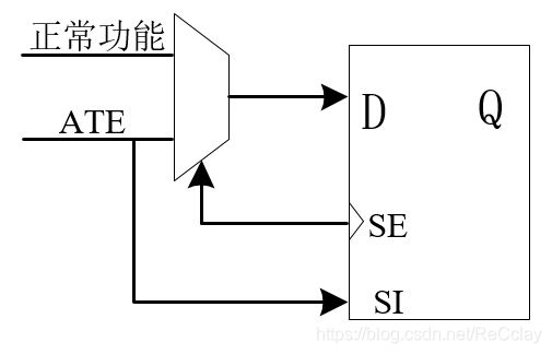
- First of all, let's introduce it in detail In front-end design DFT Realization :DFT The implementation is to insert , There are two main things to do :①、 insert ScanChain ②、 insert MBist. After the chip is streamed Manufacturing test To prepare for , Chip making is in a wafer It's done above , This wafer Logic circuits are usually realized by lithography 、 Corrosion and a series of processes , hold CMOS The pipe is wafer Make it from the top . There are inevitably some problems in this process , For example, the corrosion dose is a little higher 、 The depth of lithography is a little more , Lead to CMOS The function may not operate according to our normal function , Or some wiring stuck, Short circuit and other faults , So it needs to be done DFT circuit .
- ①、 ScanChain : After the chip comes back , adopt DFT Of ATPG(Automatic Test Pattern Generation) Automatically generate tests Pattern , Then through the chip IO, hold Pattern Pour it in , In this way, the whole chip D Triggers are strung into a chain , Then take it. Pattern Output . that D On the one hand, the trigger should realize the required logic function , On the one hand, we should realize testing (ATE), It will be in D The input of the trigger will be followed by MUX, This MUX There are two functions .MUX The enabling end of is SE(Scan Enable), Test input ATE yes SI(Scan Input).
- ②、MBist: Built in self testing , If we do logic, we will encounter a large number of logical storage units (Memory), There are two ways to realize the logic unit of digital circuit :①、 adopt D Trigger to build , But the area will be relatively large ②、 customized Memory, But it is simulated IP. Usually for D Trigger we can ScanChain Such a test , So for Memory This simulation IP, We'll do it Mbist(Memory Burn-In Scan Test) test ,Burn-In It means born , The whole Pattern yes Memory I have a layer of circuits that can generate vectors by myself , It will be right Memory All spaces will undergo an ergodic test . It goes with D Trigger ScanChain Dissimilarity ,ScanChain It's connected to the chip IO Of , Need to pass the external test bench , Give him encouragement to complete the test , however Memory There is no need for external abutment excitation , It is a test generated by the internal circuit itself Pattern , Just give it an enable signal , Just let it test itself !
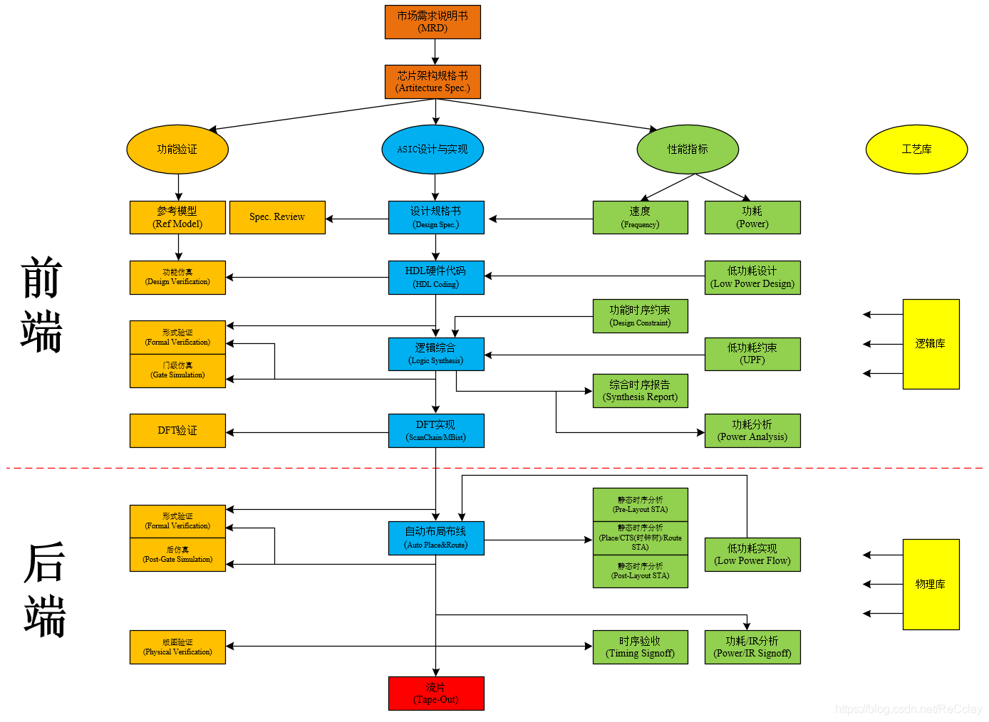
From the above 《VLSI Design flow chart 》 We can see that , Whole ASIC Designed and implemented Each stage requires corresponding verification Of ! Even after the design specification is written, a Review Link to verify . The whole design process is based on market demand , This is also the most important , Can the chip play two games , Can it sell well , There is no market demand assessment , No matter how well the chip is made . The next step is to write chip architecture specifications , Then work in parallel from the following three aspects :I、 functional verification ;II、ASIC Design and implementation ;III、 Performance indicators
I、 functional verification
stay function Ensure that every step of the design and implementation of the process conversion , It can ensure that its logic does not deform , So in 《II、ASIC Design and implementation 》 Each stage corresponds to different verification means and work .
- This column mainly studies the verification in the figure Functional simulation part , But this function simulation is not to wait for the code to come out , It comes from the architecture book , Will go to Write reference model 、 Test planning (Test Plan) And decompose each test point , At the same time, according to the function points of the architecture book , Sort out which function points to verify , Then build the environment according to these function points , After the building is completed , You also need to debug the environment . This is the time ,RTL After the code comes out , That's what makes RTL Code (DUT) Integrated into the verification environment , Perform functional verification , When the function verification passes , Will formally do logical synthesis . But in the actual engineering operation , I will give some preliminary codes to the comprehensive engineer , But that synthesis is only for debugging environment , Not officially delivered .
- Functional simulation It's our guarantee RTL Code With specifications Spec bring into correspondence with , So sometimes functional simulation will also go back and compare or even change the design specifications ., Because at this time, many verification boundaries will be designed , These boundaries cannot be reflected during the initial writing of the design specification , At this time, some use cases and test points will be constructed according to the boundary of the design itself .
- Formal verification Is to further ensure the comprehensive Netlist And RTL Logical consistency between , Therefore, every step of transformation needs to do some verifiable work , Ensure that the logic of each conversion step is equivalent , In case something goes wrong , Influence the following links !
- In addition, we will also do some after logic synthesis Gate level simulation , But this gate level simulation only runs a few use cases , It will not guarantee the whole logical function , Because the comprehensive netlist runs very slowly , The description of the network standard level is the door level description , Based on the door level ,DUT There is a lot of information ! want EDA Tools to run , Will be very slow !
- Next is DFT verification , Make sure DFT There is no problem with its own circuit ,DFT The verification is similar to the functional simulation verification above , Of course DFT The verification of is not as complex as the functional verification , Because its circuit structure is generally fixed , Therefore, it is generally directly integrated with previous projects DFT Verify the environment and run directly , And his function is not RTL So complicated .
- Next, after automatic layout and wiring , I'll do it too Formal verification . At this time, it is to ensure that the net list after layout and wiring is consistent with the integrated net list logic , And the integrated netlist logic requirements are similar to RTL Logical functions are consistent , This ensures that the layout logic function after layout and wiring is consistent with RTL Agreement .
- At the same time, after automatic layout and wiring , I'll do it too Post imitation . But the main thing at this time is not to see our functions , It depends on our Power consumption and power distribution , Is there any overheating point ,IR DROP Whether it can be satisfied .
- And finally, there's another one Layout verification (LVS), Something that will eventually be released , It is consistent with the net list function of layout and wiring .
III、 Performance indicators
More from performance Dimensions , Let's see what we're doing 《II、ASIC Design and implementation 》 Each stage of , What needs to be done .
- In the design specification stage , Need to pay attention to speed ( How high can the clock run ) And power consumption ( Whether it can meet the expected requirements ), Yes, of course , Speed and power consumption are also a pair tradeoff( Cost performance ) Things that are , High speed , Power consumption must be relatively large . This requires design to make a balanced compromise (tradeoff).
- stay RTL Coding Stage , I will do some low-power design , Of course, in the design specification stage ( low ) The strategy of power consumption is taken into account , At this time, more work is to do a gated clock (Clock Gating), Mainly through Code style To guarantee !
- In the logical synthesis stage , It will involve timing constraints and low-power constraints (Universal Power Format, abbreviation UPF), That is, the clock originally runs 100M, But the synthesis may follow a higher frequency 120M Deconstraining , Will leave a 20M Margin of , Because the timing of this stage is a load model , namely CELL The location of 、CELL Distance of 、 Information such as routing delay is not true , At this time, a fake model is used to replace , A very simple model . So I'll do some Over constrained , Leave some margin .
- Low power constraints (UPF) It describes the whole power Divide , Through division, when conducting synthesis , It is also a constraint on the comprehensive results .
- After the synthesis , Under the above two constraints , Generate comprehensive timing report and power analysis report . Iteratively modify constraints and even code according to the report .
- Static timing analysis will also be done for the stage of back-end automatic wiring , Mainly for different stages . A time series analysis is in Pre-Layout, namely Layout Before ; A timing analysis is inserting a clock tree (Clock Tree, abbreviation CTS) after , At this time, the timing path of the clock is more realistic ; The last time series analysis is in Post-Layout, That is, the layout is fixed . At the same time, a low-power analysis will also be carried out , Doing low power consumption on the back end is more a CELL Replacement , Look at some paths or CELL Timing margin (Margin), If the margin (margin) It's big , Then it will be replaced by cell The smaller , Such as : from “x4” Switch to “x2”. The smaller the drive ,CELL The longer the delay will be , about setup hold The more difficult it will be to meet . adopt timing Analysis shows that its timing has margin , We reduce it to “x2” If it can be satisfied , Let's change cell. That is, the low-power analysis at this stage is mainly replacement cell The type of , Compare the timing path cell Replace the one with low cost cell. But the power consumption benefit at this stage is generally small , There can be 5%. Therefore, the most important thing of low-power design is the initial design architecture , Process selection ,Power Format Division , Optimal control of demand , These have a great impact on power consumption . For the back-end stage , Although I will also do low power consumption , But from a system perspective , The proportion of optimized income is not so large .
- For territory , I will do the final timing convergence (Timing Signoff), therefore Timing This thing is actually very critical , Because as long as there is any point Timing dissatisfaction , Then no matter how well the previous logic function is done , Finally, the chip is still defective . So in addition to functions OK, performance Timing Also want to OK. The logic is guaranteed in function (Loigc),Timing Ensure the physical realization .【Timing yes D The trigger CELL The requirements of , That is, the requirements during the physical period 】
- Finally, we will also look at the power consumption /IR Drop Analysis of , It mainly depends on IR Drop, That is, there must be no overheating point ,IR Drop Too big , It will cause uneven heat dissipation , Long term operation of devices will burn out or shorten the service life , Accelerate its aging, etc .
Finally, let's take a look at 《VLSI Design flow chart 》 The process library on the far right
Devices in the process library , We all call it std cell, This process library is a film manufacturer (Fab) Provided !
- In the front-end stage, we use a logic library ,CELL What can be embodied is a Logic function ( And or not ).
- In the back-end stage ,CELL What more embodies is its Physics Characteristics and electrical characteristics , Such as CELL Working voltage of 、 load 、 Capacitance reactance cap、 Power consumption and other characteristics . Of course, the physical library here contains the logical information of the logical library !
Twelve 、 Review
1、 The flow of digital integrated circuit design is introduced in detail ?
This section describes a simple process 、 A complex process 、 And the detailed deployment of the front-end and back-end 、 Finally, there is a summary chart .
2、 Introduce in detail the main work done in each stage of the digital design process ?
3、 Introduce in detail the main... Used in each stage of the digital design process EDA What are the tools ?
4、 Draw the numbers IC Circuit design process and related use EDA Tools ?
5、 Draw SoC Chip architecture diagram , Be familiar with the application scenario and data flow of the chip ?
边栏推荐
- 618 "low key" curtain call, how can baiqiushangmei join hands with the brand to cross the "uncertain era"?
- C langue OJ obtenir PE, ACM démarrer OJ
- Autumn byte interviewer asked you any questions? In fact, you have stepped on thunder
- Unity编辑器扩展 UI控件篇
- leetcode刷题:二叉树15(找树左下角的值)
- Go language | 02 for loop and the use of common functions
- Multi branch structure
- 微信小程序正则表达式提取链接
- CADD课程学习(7)-- 模拟靶点和小分子相互作用 (半柔性对接 AutoDock)
- [untitled]
猜你喜欢

leetcode刷题:二叉树18(最大二叉树)
B站UP搭建世界首个纯红石神经网络、基于深度学习动作识别的色情检测、陈天奇《机器学编译MLC》课程进展、AI前沿论文 | ShowMeAI资讯日报 #07.05
淺淺的談一下ThreadLocalInsecureRandom
Elk distributed log analysis system deployment (Huawei cloud)
S7-200smart uses V90 Modbus communication control library to control the specific methods and steps of V90 servo
零道云新UI设计中

Debezium series: record the messages parsed by debezium and the solutions after the MariaDB database deletes multiple temporary tables

Leetcode: binary tree 15 (find the value in the lower left corner of the tree)
秋招字节面试官问你还有什么问题?其实你已经踩雷了

Interviewer: what is the internal implementation of set data types in redis?
随机推荐
ICTCLAS word Lucene 4.9 binding
Debezium series: parsing the default value character set
JS implementation prohibits web page zooming (ctrl+ mouse, +, - zooming effective pro test)
Debezium series: record the messages parsed by debezium and the solutions after the MariaDB database deletes multiple temporary tables
Relationship between floating elements and parent and brother boxes
1: Citation;
ffplay文档[通俗易懂]
CADD课程学习(7)-- 模拟靶点和小分子相互作用 (半柔性对接 AutoDock)
Is it safe for Guosen Securities to open an account online?
期货如何网上开户?安不安全?
关于BRAM IP复位的优先级
解决Thinkphp框架应用目录下数据库配置信息修改后依然按默认方式连接
leetcode刷题:二叉树16(路径总和)
How to select the Block Editor? Impression notes verse, notation, flowus
Complete interview questions for interviewers and senior Android engineers in front-line Internet enterprises
图嵌入Graph embedding学习笔记
leetcode刷题:二叉树15(找树左下角的值)
Unity编辑器扩展 UI控件篇
Oracle-表空间管理
Is it safe for Anxin securities to open an account online?