当前位置:网站首页>Half bridge buck circuit - record
Half bridge buck circuit - record
2022-07-28 08:32:00 【Embedded maker workshop】
The recent use IR2104+NMOS The tube makes a half bridge BUCK Step down circuit , Do some process here 、 Record of experience .
The circuit schematic diagram is shown below :

● The driver chip used is IR2104, Recommended EG2104, Because I only have IR2104, So I make do with it , As long as there is no fake chip , There won't be a big problem .
● NMOS Tube based on input VCC The voltage of , Select the appropriate withstand voltage value , Under this premise, the smaller the internal resistance, the better ( It's like bullshit )
● Bootstrap diode FR107 stay VCC No more than 40V You can use SS series ( Such as SS14) Schottky diode replacement , Include 1N4148、1N5819, In this way, only one diode model is more convenient for welding
● Switching frequency will affect MOS Loss of tube , That is, increase the calorific value , It is more obvious in the case of high current
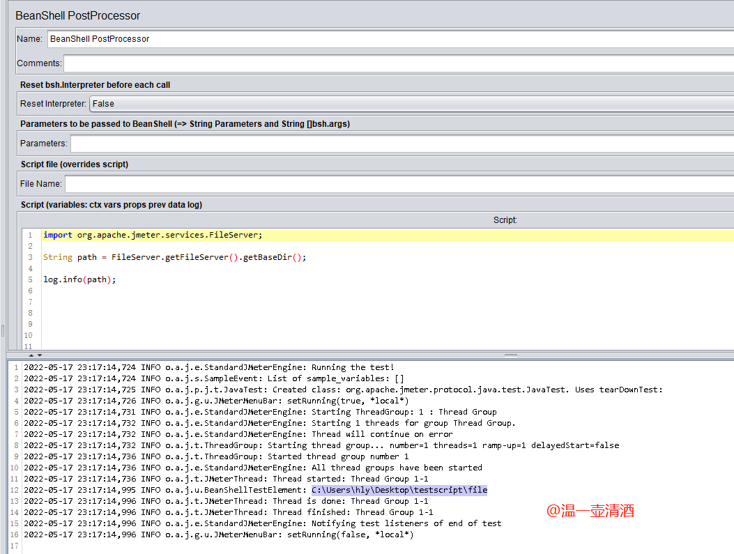
● This record focuses on typical switching spikes and oscillations . Because for the circuit made for the first time , I usually have a sparse layout , Convenient for later debugging and testing ( The first time is more about finding problems and circuit characteristics ), I didn't know before MOS There will be such problems , What problem is directly shown in the figure above is simple and clear


The difference is NMOS On tube 、 The conduction waveform of the lower tube , The test conditions are VCC=30V, Output 12V、1.5A
It can be seen that there are spikes and serious oscillations when the upper tube is switched , After consulting the information, I learned that this is a typical problem , I referred to this article later :BUCK How on earth does peak oscillation occur ? This is a very in-depth article , If you want to know more about it, you can take a look
From this article , I can find that one of the problems of my board is the signal line of the upper and lower tubes , Drive the chip to NMOS The grid line is a little long , Later, the second time Layout when , I draw the layout more compact , Sure enough , Problem solved
The following figure shows the conduction waveform of the upper and lower tubes , You can see , Almost perfect . The test conditions are VCC=30V, Output 12V、1.5A


That's it , I hope it can help you .
边栏推荐
猜你喜欢

Can the variable modified by final be modified

Common solutions for distributed ID - take one

Prescan quick start to master the road elements of lecture 15
How to write a JMeter script common to the test team
Is the salary of test / development programmers unbalanced? Busy life, all kinds of job hopping

Kubernetes技术与架构(七)
Es6: arrow function usage
![Redis of non relational database [detailed setup of redis cluster]](/img/0b/bd05fb91d17f6e0dc9f657a4047ccb.png)
Redis of non relational database [detailed setup of redis cluster]

Tell you step by step what you need to do to apply for PMP? What should I do?

EMC EMI磁珠的特性
随机推荐
解决CNN固有缺陷!通用 CNN 架构CCNN来了| ICML2022
Matlab file path
Prescan quick start to proficient in lecture 17, speed curve editor
Allure use
Can a flinksql script write insert statements for two tables?
[leetcode] 24. Exchange nodes in the linked list in pairs
How to build the protection system of class protection technology of 2022 series of ISO compliance (Part I)
JS thoroughly understand this point
Get the clicked line number in qtablewidget
Qt使用信号量控制线程(QSemaphore)
[Qt5] a method of multi window parameter transmission (using custom signal slot) and case code download
What if you are prompted that your connection to this website is not a private connection?
[environment configuration] ppyoole trains its own data set (for its own use)
Prescan quick start to master the track editing path of Lecture 16
对spark算子aggregateByKey的理解
Usage of constructors
Regular expression for mobile number verification
聊一聊数据库的行存与列存
pyspark 写入数据到iceberg
二维数组及操作