当前位置:网站首页>Structural modeling and Design -- a practical summary of the functions of rotary cutting and fillet chamfering in feature forming of SolidWorks software (drawing a countersunk screw hole)
Structural modeling and Design -- a practical summary of the functions of rotary cutting and fillet chamfering in feature forming of SolidWorks software (drawing a countersunk screw hole)
2022-06-21 18:06:00 【Winter_ world】
【 Series column 】: Blogger's output combined with work practice , Column on solving practical problems , Friends, look !
《QT Developing actual combat 》
《 Embedded general development practice 》
《 from 0 To 1 Learn Embedded Linux Development 》
Bring more cases and technical articles to share for a long time ;
Welcome to business project consultation ,10 year + Soft and hard internal skill of the whole stack , Help solve your noble needs .
——————————————————————————————————
Catalog
0 introduction
In this blog post, we will continue to learn about the rotation cutting in feature forming , And fillet and chamfer functions , Draw a countersunk screw hole with the rotary cutting function , And demonstrate how to use fillet and chamfer , Also cooperate with actual combat practice , Learning from scratch .
1 Rotary cutting function
The rotary cutting is similar to the rotary boss matrix , The former is to reduce the material , The latter is to add materials , Let's use the rotation resection function , Draw a countersunk screw hole .
First , Draw a cube with equal sides
—— Click the forward reference plane , Draw a two-point rectangle , The starting point is the origin
—— Select two adjacent edges of the rectangle at the same time , Set the attribute to equal length , Use the intelligent dimension tool to set the side length to 25mm
—— Click to stretch the boss matrix , The depth is set to 25mm, Click ok , Get a side length 25mm The cube
Let's do a rotational resection in the middle of the cube , Because the three existing datum planes are not in the center of the cube , So we need to establish a datum plane in the middle of the cube , Let's look at the specific steps :
—— Click the reference geometry... In the feature bar , Select datum from the pop-up menu
—— At this time, the first reference in the left property bar is activated , Click on a face of the cube , This face is added
—— Click reverse isometric , Set the distance to 12.5mm( Because the side length of the cube is 25mm)
—— If you don't want to deliberately set the reverse isometric distance , You also want the datum plane to be in the middle of the cube , You can select the first and second reference faces , Set the attribute to bilateral symmetry
The next step is to draw the rotation cut :
—— Click the newly created datum , Start sketching
—— Use the midpoint constraint of the upper and lower edge lines , Draw a construction line (Alt+C Shortcut key ), As the axis of rotation
—— Draw the cross section of the countersunk screw hole , Use the intelligent dimension tool to set the dimension , Counterbore radius 7.8mm, Screw hole radius 4.5mm, Counterbore angle 45 degree
—— Click rotate to cut , Click is , The sketch closes automatically , And rotate to cut .
Rotate to view the current entity , Is it convenient to see the internal structure ? We can use the section view to view :
—— Click the datum plane in the middle of the cube
—— Click the section view button in the view tool (Section View), The section view is visible
—— In the left attribute bar, you can set the distance between the section and the datum plane
—— Click the OK button , Observe the section view ( Only the function of the parts window , No cutting model )
—— Click the section view button again , Cancel .
2 Fillets and chamfers
Continue to build on the cube above , Draw rounded corners and chamfers
—— Click the fillet button , The first column of the property bar is the fillet type , The first common
—— The second column of the property bar is the item to be rounded , Select an edge , Then the right angle of the edge line becomes a rounded corner , You can also click on a face , Then the right angles of the edges on the face become rounded corners
—— The radius of the fillet can be set in the property bar
—— Click the chamfer button , Click on the edge of the cube , You can also click on a face , The operation procedure is similar to that of fillet :
3 summary
This blog post summarizes the use of rotation cutting and fillet chamfering functions in feature forming , It used to be thought that drawing a screw hole in structural modeling and design required surveying and mapping a lot of dimensions , Drawing a screw hole entity is troublesome , In fact, I have mastered some practical functions of the software , It is easy to draw some seemingly not simple structures , Continue to learn , Make persistent efforts .
As in the 202206201600, Filed
———————————————————————————————————
This article is an original blog article , No reprint without the permission of the blogger !
If this article is helpful to you , Lift your little hand to make a fortune , Focus on / Comment on / give the thumbs-up / Collection , Is the greatest support for me !
I wish you a promotion and a raise , have a bright future !
边栏推荐
- postman关联,完成接口自动化测试
- Nacos registry ----- built and used from 0
- What is the difference between IEC62133 and EN62133? Which items are mainly tested?
- LeetCode_ String_ Simple_ 387. first unique character in string
- EtherCAT igh函数尝试
- Not graduated from a first-class university, but passed the self-study software test and entered the initial 22K annual salary of Alibaba
- RT-Thread 柿饼派M7 全志F133 ddr 运行xboot
- 透过华为军团看科技之变(四):互动媒体(音乐)
- Zhong'an insurance, together with Alibaba health and huiyitianxia, explores a new model of Internet chronic disease management
- Stack cognition -- basic use of reverse IDA tools
猜你喜欢

Stack awareness - stack overflow instance (ret2libc)

Simulation of vector

天天在都在谈的S3协议到底是什么?一文带你了解S3背后的故事

透过华为军团看科技之变(四):互动媒体(音乐)

【蓝桥杯省赛真题35】Scratch水面倒影 少儿编程scratch编程蓝桥杯省赛真题讲解

大型网站技术架构 | 信息加密技术及密匙安全管理

我被变相降薪了
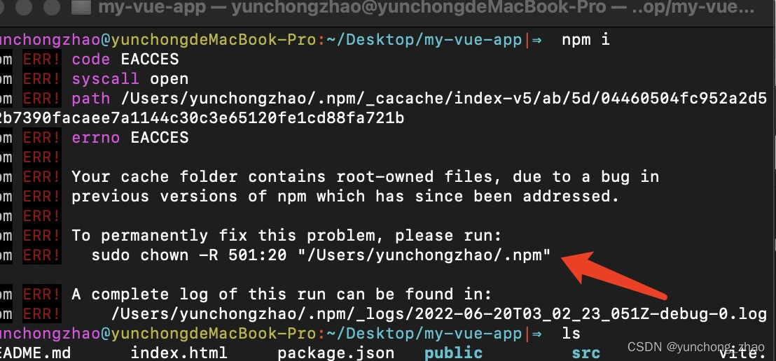
Your cache folder contains root-owned files, due to a bug in npm ERR! previous versions of npm which

POSIX信号量

RT-Thread 柿饼派M7 全志F133 ddr 运行xboot
随机推荐
堆栈认知——逆向IDA工具的基本使用
list的使用
Win32com operation Excel
在线直播系统源码,实现进入页面就去请求列表接口并触底分页加载
POSIX信号量
Lua导出为外部链接库并使用
Zhong'an insurance, together with Alibaba health and huiyitianxia, explores a new model of Internet chronic disease management
Analysis of 43 cases of MATLAB neural network: Chapter 26 classification of LVQ Neural Network - breast tumor diagnosis
堆栈认知——栈溢出实例(ret2shellcode)
STM32F1与STM32CubeIDE编程实例-线性霍尔效应传感器驱动
Vit is crazy, 10+ visual transformer model details
C语言与Lua的交互(实践三)
National administrative division
PHP输出函数
EtherCAT igh 'Fatal Sync Error'——0x002C,0x001A
list的模拟实现
Let, with, apply, also, run
Stack awareness - stack overflow instance (ret2text)
PHP连接Mysql8.0报错:Illuminate\Database\QueryException
[dataset] |bigdetection