当前位置:网站首页>[FPGA] EEPROM based on I2C
[FPGA] EEPROM based on I2C
2022-07-07 06:15:00 【EPCCcc】
List of articles
One 、i2c agreement
I2C The bus is made up of Philips The company developed a simple 、 Two way two wire synchronous serial bus . It only needs two wires to transmit information between devices connected to the bus .
I2C It is a bus that can support multiple devices , Contains a two-way serial data line SDA, A serial clock line SCL.
Two 、 see i2c–eeprom Find the key
1. Select different models
![[ Failed to transfer the external chain picture , The origin station may have anti-theft chain mechanism , It is suggested to save the pictures and upload them directly (img-ONIcX1t7-1644636161350)(C:\Users\Jin\AppData\Roaming\Typora\typora-user-images\image-20220117211209367.png)]](/img/28/f4f2efda4b5feb973c9cf07d9d908f.jpg)
I use it here C4 The board of ,24LC04B, The highest clock is 400kHZ
2. describe
![[ Failed to transfer the external chain picture , The origin station may have anti-theft chain mechanism , It is suggested to save the pictures and upload them directly (img-JhxhnjaY-1644636161352)(C:\Users\Jin\AppData\Roaming\Typora\typora-user-images\image-20220117205934633.png)]](/img/47/51f5ecc28c39eb31764f5fe72f4ac7.jpg)
EEPROM The storage size of is 2 individual block, One block yes 256*8bit The storage size of
3. Bus sequence diagram
![[ Failed to transfer the external chain picture , The origin station may have anti-theft chain mechanism , It is suggested to save the pictures and upload them directly (img-DVIITcGL-1644636161352)(C:\Users\Jin\AppData\Roaming\Typora\typora-user-images\image-20220117214117925.png)]](/img/5a/e9395e0d8dce4a4131768d956bacf5.jpg)
4. Bus start and stop
![[ Failed to transfer the external chain picture , The origin station may have anti-theft chain mechanism , It is suggested to save the pictures and upload them directly (img-kz8HnP2U-1644636161352)(C:\Users\Jin\AppData\Roaming\Typora\typora-user-images\image-20220117214234625.png)]](/img/e5/885deee2bfa6b1fda609aaa22a8459.jpg)
Red To mark the beginning
green For the end sign
5. Data is transmitted on the bus
![[ Failed to transfer the external chain picture , The origin station may have anti-theft chain mechanism , It is suggested to save the pictures and upload them directly (img-1oqQu8b8-1644636161353)(C:\Users\Jin\AppData\Roaming\Typora\typora-user-images\image-20220117215013538.png)]](/img/28/39ba104a4edb447bcf7d3728991535.jpg)
6. Device address ( Control command )
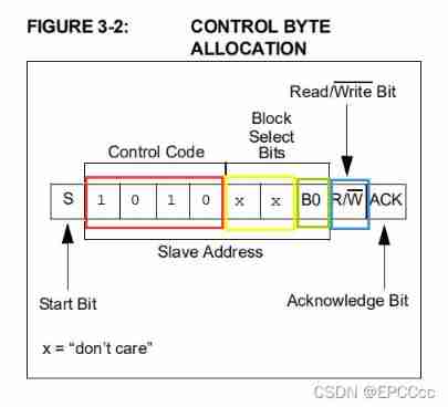
![[ Failed to transfer the external chain picture , The origin station may have anti-theft chain mechanism , It is suggested to save the pictures and upload them directly (img-dEzS8vrL-1644636161353)(C:\Users\Jin\AppData\Roaming\Typora\typora-user-images\image-20220117215434569.png)]](/img/a2/36229e5827b94e09b5e0949d0eb9dc.jpg)
Device address is also called control command , It's one byte
| operation | Control Code | Block Select | R/W |
|---|---|---|---|
| read | 1010( Yes 24XX04, 1010 It's a read-write operation ) | XX( Yes 24XX04, These two don’t care) | 1 |
| Write | 1010( Yes 24XX04, 1010 It's a read-write operation ) | XX( Yes 24XX04, These two don’t care) | 0 |
7. Write operations
![[ Failed to transfer the external chain picture , The origin station may have anti-theft chain mechanism , It is suggested to save the pictures and upload them directly (img-LYKCNbKQ-1644636161353)(C:\Users\Jin\AppData\Roaming\Typora\typora-user-images\image-20220118093253930.png)]](/img/f6/f989954c2dd7c6f7dfec112faf6a4a.jpg)
- Single byte write
- Single byte write first start bit ,
- Then write the control byte , The slave receives and sends a reply signal ,
- Then write the data address , The slave receives and sends a reply signal , If the data address is 2 A word of , Just keep writing the data address , The slave receives and sends a reply signal ,
- And then write the data , The slave receives and sends a reply signal ,
- The last is the ending bit .
![[ Failed to transfer the external chain picture , The origin station may have anti-theft chain mechanism , It is suggested to save the pictures and upload them directly (img-bXYSGXhd-1644636161353)(C:\Users\Jin\AppData\Roaming\Typora\typora-user-images\image-20220118094127139.png)]](/img/70/6bd08d9f0090f8bc099d0c94a3fa36.jpg)
- Page writing
- The beginning bit of page section writing ,
- Then write the control byte , The slave receives the reply signal ,
- Then write the data address , The slave receives the reply signal , If the data address is 2 A word of , Just keep writing the data address , The slave receives the reply signal ,
- And then write the data , The slave receives the reply signal ,
- Then continue to write data , Until all the data is written ,
- The last is the ending bit .
8. Read operations
![[ Failed to transfer the external chain picture , The origin station may have anti-theft chain mechanism , It is suggested to save the pictures and upload them directly (img-QUzTpOFs-1644636161354)(C:\Users\Jin\AppData\Roaming\Typora\typora-user-images\image-20220118095216519.png)]](/img/eb/2e89807cfdc8d607242a2b7315d935.jpg)
- The current address is read
After the current read or write operation ,24XX04 There is an address counter inside , Will increase by one , So the current address is read to the next address .
- The current address reads the start bit first ,
- Then write the control byte , The slave receives the reply signal , Then read the data , No reply signal ,
- Last ending bit
![[ Failed to transfer the external chain picture , The origin station may have anti-theft chain mechanism , It is suggested to save the pictures and upload them directly (img-mGYkiBvq-1644636161354)(C:\Users\Jin\AppData\Roaming\Typora\typora-user-images\image-20220118095232335.png)]](/img/04/4a9d85d6705509c339bdb60a00bc69.jpg)
- random block read
- Random read start bit ,
- Then write the control byte , The slave receives the reply signal ,
- then dummuy write describe indirectly , Write data address , The slave receives the reply signal ,
- Then start bit ,
- Then read the control byte , The slave receives the reply signal
- Then read the data
- Last ending bit
![[ Failed to transfer the external chain picture , The origin station may have anti-theft chain mechanism , It is suggested to save the pictures and upload them directly (img-DrFrovvV-1644636161354)(C:\Users\Jin\AppData\Roaming\Typora\typora-user-images\image-20220118095247274.png)]](/img/bb/57adf9e5f55db238b7e24b28a91446.jpg)
- Sequential reading
- Sequential reading is an enhanced version of random reading , Read a lot of data
3、 ... and 、 State machine design
1.i2c State diagram of protocol interface
![[ Failed to transfer the external chain picture , The origin station may have anti-theft chain mechanism , It is suggested to save the pictures and upload them directly (img-i0pKBBKl-1644636161355)(C:\Users\Jin\AppData\Roaming\Typora\typora-user-images\image-20220121141711475.png)]](/img/6b/1b9f1b84691aea53c0835d9da95942.jpg)
2.eeprom Read write state diagram
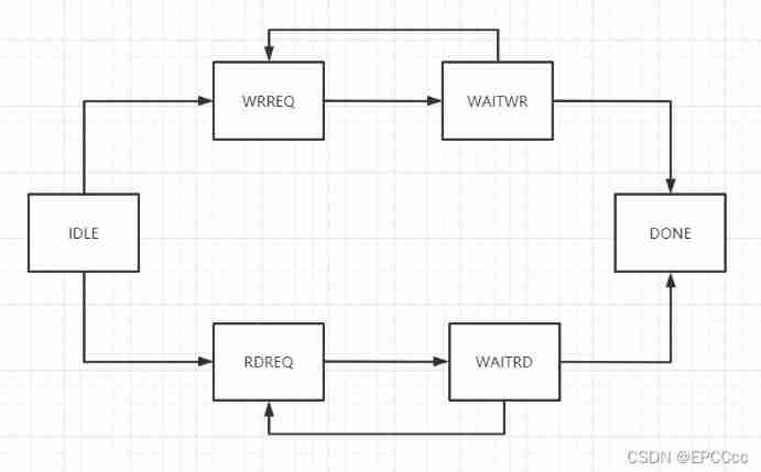
matters needing attention
eeprom It's a high starter ,
Four 、 Code section
1.i2c_interface.v
// i2c Interface module
module i2c_interface(
    input           clk,
    input           rst_n,
    //  Interface and eeprom  Single bus sda
    output          scl,
    input           sda_in,
    output          sda_out,
    output          sda_out_en,
    //  Interface with host
    input           req,
    input   [3:0]   cmd,
    input   [7:0]   din,
    output          slave_ack,
    output  [7:0]   dout,
    output          done
);

// i2c compatible 100kHZ-400kHZ, Here we use 200kHZ
//  Let's pull down first sclk, Pull up again sclk
parameter   SCL_TIME       = 250,// 200kHZ  A cycle of
            SCL_HALF_TIME  = 125,// 200kHZ  Half cycle of
            SCL_LOW_MID    = 65,//
            SCL_HIGH_MID   = 185;

//  Start reading and writing end command
localparam  START_CMD = 4'b0001,
            WRITE_CMD = 4'b0010,
            READ_CMD  = 4'b0100,
            STOP_CMD  = 4'b1000;

localparam  IDLE   = 7'b000_0001,//  Default state
            START  = 7'b000_0010,//  Start bit
            WRITE  = 7'b000_0100,//  Write status
            READ   = 7'b000_1000,//  Read status
            SEDACK = 7'b001_0000,//  Send reply signal status
            RECACK = 7'b010_0000,//  Receive reply signal status
            STOP   = 7'b100_0000;//  Stop bit

//  State machine
reg     [6:0]       state_c;
reg     [6:0]       state_n;

//  State transition conditions
wire                idle2start  ;
wire                idle2write  ;
wire                idle2read   ;
wire                start2write ;
wire                start2read  ;
wire                write2recack;
wire                read2sedack ;
wire                sedack2stop ;
wire                sedack2idle ;
wire                recack2stop ;
wire                recack2idle ;
wire                stop2idle   ;

//  Serial clock counter   When to pull higher and when to pull lower
reg     [8:0]       cnt_scl;
wire                add_cnt_scl;
wire                end_cnt_scl;

// bit Counter
reg     [3:0]       cnt_bit;
wire                add_cnt_bit;
wire                end_cnt_bit;

//  Deposit i2c Interface and eeprom The data of
reg                 i2c_scl;
reg                 i2c_sda_out;
reg                 i2c_sda_out_en;
//  Deposit receipt from eeprom Data sent
reg     [7:0]       rx_data;
//  The hosting host receives the response signal from the slave
reg                 rx_ack;

//  State machine
always @(posedge clk or negedge rst_n)begin
    if(!rst_n)begin
        state_c <= IDLE;
    end
    else begin
        state_c <= state_n;
    end
end

always @(*)begin
    case (state_c)
        IDLE      :begin
                    if(idle2start)begin
                        state_n = START;
                    end
                    else if(idle2write)begin
                        state_n = WRITE;
                    end
                    else if(idle2read)begin
                        state_n = READ;
                    end
                    else begin
                        state_n = state_c;
                    end
                   end
        START      :begin
                    if(start2write)begin
                        state_n = WRITE;
                    end
                    else if(start2read)begin
                        state_n = READ;
                    end
                    else begin
                        state_n = state_c;
                    end
                   end
        WRITE      :begin
                    if(write2recack)begin
                        state_n = RECACK;
                    end
                    else begin
                        state_n = state_c;
                    end
                   end
        READ      :begin
                    if(read2sedack)begin
                        state_n = SEDACK;
                    end
                    else begin
                        state_n = state_c;
                    end
                   end
        SEDACK      :begin
                    if(sedack2stop)begin
                        state_n = STOP;
                    end
                    else if(sedack2idle)begin
                        state_n = IDLE;
                    end
                    else begin
                        state_n = state_c;
                    end
                   end
        RECACK      :begin
                    if(recack2stop)begin
                        state_n = STOP;
                    end
                    else if(recack2idle)begin
                        state_n = IDLE;
                    end
                    else begin
                        state_n = state_c;
                    end
                   end
        STOP      :begin
                    if(stop2idle)begin
                        state_n = IDLE;
                    end
                    else begin
                        state_n = state_c;
                    end
                   end
        default: state_n = IDLE;
    endcase
end

assign idle2start   = state_c == IDLE   && (req && (cmd & START_CMD));//  Start at your request
assign idle2write   = state_c == IDLE   && (req && (cmd & WRITE_CMD)); //  Have a request and continue writing
assign idle2read    = state_c == IDLE   && (req && (cmd & READ_CMD));//  Request and continue reading
assign start2write  = state_c == START  && (end_cnt_bit && (cmd & WRITE_CMD));// 1bit Start bit
assign start2read   = state_c == START  && (end_cnt_bit && (cmd & READ_CMD));// 1bit1 Start bit
assign write2recack = state_c == WRITE  && (end_cnt_bit);// 8bit The data is written
assign read2sedack  = state_c == READ   && (end_cnt_bit);// 8bit The data is written
assign sedack2stop  = state_c == SEDACK && (end_cnt_bit && (cmd & STOP_CMD));// 1bit Send reply signal
assign sedack2idle  = state_c == SEDACK && (end_cnt_bit && (cmd & STOP_CMD) == 0);//  No stop command   Just go ahead
assign recack2stop  = state_c == RECACK && (end_cnt_bit && (cmd & STOP_CMD));// 1bit Receive a reply signal
assign recack2idle  = state_c == RECACK && (end_cnt_bit && (cmd & STOP_CMD) == 0);//  No stop command   Just go ahead
assign stop2idle    = state_c == STOP   && (end_cnt_bit);// 1bit Receive bit

//  Serial clock counter
always @(posedge clk or negedge rst_n)begin
   if(!rst_n)begin
        cnt_scl <= 0;
    end
    else if(add_cnt_scl)begin
            if(end_cnt_scl)begin
                cnt_scl <= 0;
            end
            else begin
                cnt_scl <= cnt_scl + 1;
            end
    end
   else  begin
       cnt_scl <= cnt_scl;
    end
end

assign add_cnt_scl = (state_c != IDLE);
assign end_cnt_scl = add_cnt_scl && cnt_scl == SCL_TIME - 1;

// bit Counter
always @(posedge clk or negedge rst_n)begin
   if(!rst_n)begin
        cnt_bit <= 0;
    end
    else if(add_cnt_bit)begin
            if(end_cnt_bit)begin
                cnt_bit <= 0;
            end
            else begin
                cnt_bit <= cnt_bit + 1;
            end
    end
   else  begin
       cnt_bit <= cnt_bit;
    end
end

assign add_cnt_bit = end_cnt_scl;
assign end_cnt_bit = add_cnt_bit && cnt_bit == (((state_c == WRITE) || (state_c == READ))?(8 - 1):(1 - 1));

//  The serial clock scl
//  Use the counter to form a serial clock
always @(posedge clk or negedge rst_n)begin
    if(!rst_n)begin
        i2c_scl <= 1;
    end
    else if(idle2start || idle2write || idle2read)begin
        i2c_scl <= 1'b0;
    end
    else if(add_cnt_scl && (cnt_scl == SCL_HALF_TIME))begin
        i2c_scl <= 1'b1; //
    end
    else if(end_cnt_scl)begin
        i2c_scl <= 1'b0;
    end
    else if(stop2idle)begin
        i2c_scl <= 1'b1;
    end
end

// sda data bus
// sda_in
//  In the middle time when the serial bus is high, the data is collected stably eeprom The data of
//  Serial to parallel conversion
always @(posedge clk or negedge rst_n)begin
    if(!rst_n)begin
        rx_data <= 0;
    end
    else if((state_c == READ) && add_cnt_scl && (cnt_scl == SCL_HIGH_MID))begin
        rx_data[7-cnt_bit] <= sda_in;
    end
end

// sda_in
//  The master samples the response signal of the slave
always @(posedge clk or negedge rst_n)begin
    if(!rst_n)begin
        rx_ack <= 1'b1;
    end
    else if((state_c == RECACK) && add_cnt_scl && (cnt_scl == SCL_HIGH_MID))begin
        rx_ack <= sda_in;
    end
end

// sda_out
//  At the intermediate moment when the serial bus is low, the data changes to eeprom Sending data
//  Serial to parallel conversion
always @(posedge clk or negedge rst_n)begin
    if(!rst_n)begin
        i2c_sda_out <= 0;
    end
    else if(state_c == START)begin
        if(add_cnt_scl && cnt_scl == SCL_LOW_MID)begin
            i2c_sda_out <= 1'b1; //  Ensure that the previous state is not pulled down , Pull it up first , Detection start bit
        end
        else if(add_cnt_scl && cnt_scl == SCL_HIGH_MID)begin
            i2c_sda_out <= 1'b0; //  Detection start bit
        end
    end
    else if(state_c == STOP)begin
        if(add_cnt_scl && cnt_scl == SCL_LOW_MID)begin
            i2c_sda_out <= 1'b0; //  Ensure that the previous state is not pulled down , Pull it up first , Detection end bit
        end
        else if(add_cnt_scl && cnt_scl == SCL_HIGH_MID)begin
            i2c_sda_out <= 1'b1; //  Detection end bit
        end
    end
    else if((state_c == WRITE) && add_cnt_scl && (cnt_scl == SCL_LOW_MID))begin
        i2c_sda_out <= din[7-cnt_bit]; //  Serial parallel conversion data
    end
    else if((state_c == SEDACK) && add_cnt_scl && (cnt_scl == SCL_LOW_MID))begin
        i2c_sda_out <= (cmd & STOP_CMD)?1'b1:1'b0;//  Send reply signal
    end
end

// sda_out_en
always @(posedge clk or negedge rst_n)begin
    if(!rst_n)begin
        i2c_sda_out_en <= 0;
    end
    else if(idle2start || idle2write || start2write || read2sedack || sedack2stop || recack2stop)begin
        i2c_sda_out_en <= 1'b1;
    end
    else if(idle2read || start2read || write2recack || sedack2idle || recack2idle || stop2idle)begin
        i2c_sda_out_en <= 1'b0;
    end
end

assign scl = i2c_scl;
assign sda_out = i2c_sda_out;
assign sda_out_en = i2c_sda_out_en;
assign dout = rx_data;
//  The master receives the response signal from the slave
assign slave_ack = rx_ack;
//  A byte  8bit It's over done
assign done = sedack2idle || recack2idle || stop2idle;

endmodule
2.master_ctrl.v
module master_ctrl(
    input           clk,
    input           rst_n,
    //  Key
    input   [1:0]   key_out,
    //  Interface with host
    output          req,
    output  [3:0]   cmd,
    output  [7:0]   dout,
    input           slave_ack,
    input           done,
    input   [7:0]   rx_data,
    //  Nixie tube
    output  [23:0]  seg_data,
    //  A serial port uart
    input   [7:0]   uart_rx_data,
    input           uart_rx_data_vld,
    output  [7:0]   uart_tx_data,
    output          uart_tx_data_vld,
    input           busy
);

parameter   DEVICE_ID = 7'b1010_000,//  Device address  + block(dont care)
            WR_ID     = 1'b0,//  Control writing
            RD_ID     = 1'b1;//  Control reading

parameter   WR_LEN = 16+2,//  Bytes written
            RD_LEN = 16+3;//  Bytes read

//  Start reading and writing end command
localparam  START_CMD = 4'b0001,
            WRITE_CMD = 4'b0010,
            READ_CMD  = 4'b0100,
            STOP_CMD  = 4'b1000;

localparam  IDLE   = 6'b000_001,
            WRREQ  = 6'b000_010,
            WAITWR = 6'b000_100,
            RDREQ  = 6'b001_000,
            WAITRD = 6'b010_000,
            DONE   = 6'b100_000;

reg     [5:0]       state_c;
reg     [5:0]       state_n;

wire                idle2wrreq  ;
wire                idle2rdreq  ;
wire                wrreq2waitwr;
wire                WAITWR2wrreq;
wire                waitwr2done ;
wire                rdreq2waitrd;
wire                waitrd2rdreq;
wire                waitrd2done ;

//  Byte counter   One block Maximum 256
reg     [7:0]       cnt_byte;
wire                add_cnt_byte;
wire                end_cnt_byte;

//  Read write request
reg                 wr_req;
reg                 rd_req;

//  Deposit what you want to export req cmd dout
reg                 tx_req;
reg     [3:0]       tx_cmd;
reg     [7:0]       tx_data;

// wrfifo Parameters
wire                wrfifo_rdreq;
wire                wrfifo_wrreq;
wire                wrfifo_empty;
wire                wrfifo_full ;
wire    [7:0]       wrfifo_qout ;
wire    [7:0]       wrfifo_usedw;

// rdfifo Parameters
wire                rdfifo_rdreq;
wire                rdfifo_wrreq;
wire                rdfifo_empty;
wire                rdfifo_full ;
wire    [7:0]       rdfifo_qout ;
wire    [7:0]       rdfifo_usedw;
//  State machine
always @(posedge clk or negedge rst_n)begin
    if(!rst_n)begin
        state_c <= IDLE;
    end
    else begin
        state_c <= state_n;
    end
end

always @(*)begin
    case (state_c)
        IDLE      :begin
                    if(idle2wrreq)begin
                        state_n = WRREQ;
                    end
                    else if(idle2rdreq)begin
                        state_n = RDREQ;
                    end
                    else begin
                        state_n = state_c;
                    end
                   end
        WRREQ      :begin
                    if(wrreq2waitwr)begin
                        state_n = WAITWR;
                    end
                    else begin
                        state_n = state_c;
                    end
                   end
        WAITWR      :begin
                    if(WAITWR2wrreq)begin
                        state_n = WRREQ;
                    end
                    else if(waitwr2done)begin
                        state_n = DONE;
                    end
                    else begin
                        state_n = state_c;
                    end
                   end
        RDREQ      :begin
                    if(rdreq2waitrd)begin
                        state_n = WAITRD;
                    end
                    else begin
                        state_n = state_c;
                    end
                   end
        WAITRD      :begin
                    if(waitrd2rdreq)begin
                        state_n = RDREQ;
                    end
                    else if(waitrd2done)begin
                        state_n = DONE;
                    end
                    else begin
                        state_n = state_c;
                    end
                   end
        DONE      : begin
                    if(done2idle)begin
                        state_n = IDLE;
                    end
                    else begin
                        state_n = state_c;
                    end
                    end
        default: state_n = IDLE;
    endcase
end

assign idle2wrreq   = state_c == IDLE   && (wr_req);//  Write requests
assign idle2rdreq   = state_c == IDLE   && (rd_req);//  Read request
assign wrreq2waitwr = state_c == WRREQ  && (1'b1);//  Wait a cycle
assign WAITWR2wrreq = state_c == WAITWR && (~slave_ack && done && ~end_cnt_byte);//  After writing a byte, the slave sends a reply signal, but not all bytes are written
assign waitwr2done  = state_c == WAITWR && ((slave_ack || end_cnt_byte) && done);//  After writing a byte, the slave does not send an answer signal or writes all bytes
assign rdreq2waitrd = state_c == RDREQ  && (1'b1);//  Wait a cycle
assign waitrd2rdreq = state_c == WAITRD && (~slave_ack && done && ~end_cnt_byte);//  After writing a byte, the slave sends a reply signal, but not all bytes are written
assign waitrd2done  = state_c == WAITRD && ((slave_ack || end_cnt_byte) && done);//  After writing a byte, the slave does not send an answer signal or writes all bytes
assign done2idle    = state_c == DONE   && (1'b1);

//  Byte counter
always @(posedge clk or negedge rst_n)begin
    if(!rst_n)begin
        cnt_byte <= 0;
    end
    else if(add_cnt_byte)begin
            if(end_cnt_byte)begin
                cnt_byte <= 0;
            end
            else begin
                cnt_byte <= cnt_byte + 1;
            end
    end
    else if((state_c == WAITWR) && (slave_ack == 0) && done)begin
        cnt_byte <= 0;
    end
    else  begin
       cnt_byte <= cnt_byte;
    end
end

assign add_cnt_byte = ((state_c == WAITRD || state_c == WAITWR) && done);
assign end_cnt_byte = add_cnt_byte && cnt_byte == ((state_c == WAITWR)?(WR_LEN - 1):(RD_LEN - 1));

// rd_req and wr_req
always @(posedge clk or negedge rst_n)begin
    if(!rst_n)begin
        rd_req <= 0;
        wr_req <= 0;
    end
    else if(key_out[0])begin
        wr_req <= 1'b1;
    end
    else if(key_out[1])begin
        rd_req <= 1'b1;
    end
    else begin
        rd_req <= 0;
        wr_req <= 0;
    end
end

//  Different byte Send different cmd din
always @(posedge clk or negedge rst_n)begin
    if(!rst_n)begin
        tx_req  <= 0;
        tx_cmd  <= 4'b0;
        tx_data <= 8'b0;
    end
    else if(state_c == WRREQ)begin
        case(cnt_byte)
        0   :   begin
                    tx_req  <= 1;
                    tx_cmd  <= {START_CMD | WRITE_CMD};
                    tx_data <= {DEVICE_ID,WR_ID};
                end
        1   :   begin
                    tx_req <= 1;
                    tx_cmd <= WRITE_CMD;
                    tx_data <= 8'b0001_0001;
                end
        WR_LEN-1:   begin
                    tx_req <= 1;
                    tx_cmd <= {STOP_CMD | WRITE_CMD};
                    tx_data <= wrfifo_qout;
                end

        default :begin
                    tx_req <= 1;
                    tx_cmd <= WRITE_CMD;
                    tx_data <= wrfifo_qout;
                end
        endcase
    end
    else if(state_c == RDREQ)begin
        case(cnt_byte)
        0   :   begin
                    tx_req  <= 1;
                    tx_cmd  <= {START_CMD | WRITE_CMD};
                    tx_data <= {DEVICE_ID,WR_ID};
                end
        1   :   begin
                    tx_req <= 1;
                    tx_cmd <= WRITE_CMD;
                    tx_data <= 8'b0001_0001;
                end
        2   :   begin
                    tx_req  <= 1;
                    tx_cmd  <= {START_CMD | WRITE_CMD};
                    tx_data <= {DEVICE_ID,RD_ID};
                end
        RD_LEN-1   :   begin
                    tx_req <= 1;
                    tx_cmd <= {STOP_CMD | READ_CMD};
                    tx_data <= 0;
                end
        default :begin
                    tx_req <= 1;
                    tx_cmd <= READ_CMD;
                    tx_data <= 0;
                end
        endcase
    end
    else begin
        tx_req  <= 0;
        tx_cmd  <= tx_cmd;
        tx_data <= tx_data;
    end
end

//  Example writing fifo
wrfifo	wrfifo_inst (
	.clock  ( clk      ),
	.data   ( uart_rx_data ),
	.rdreq  ( wrfifo_rdreq ),
	.wrreq  ( wrfifo_wrreq ),
	.empty  ( wrfifo_empty ),
	.full   ( wrfifo_full ),
	.q      ( wrfifo_qout ),
	.usedw  ( wrfifo_usedw )
	);

assign wrfifo_wrreq = ~wrfifo_full && uart_rx_data_vld;
assign wrfifo_rdreq = ~wrfifo_empty && state_c == WAITWR && done && cnt_byte > 2;

//  Example reading fifo
rdfifo	rdfifo_inst (
	.clock  ( clk ),
	.data   ( rx_data ),
	.rdreq  ( rdfifo_rdreq ),
	.wrreq  ( rdfifo_wrreq ),
	.empty  ( rdfifo_empty ),
	.full   ( rdfifo_full ),
	.q      ( rdfifo_qout ),
	.usedw  ( rdfifo_usedw )
	);

assign rdfifo_wrreq = ~rdfifo_full && state_c == WAITRD && done && cnt_byte > 3;
assign rdfifo_rdreq = ~rdfifo_empty && ~busy;

assign req = tx_req;
assign cmd = tx_cmd;
assign dout = tx_data;

assign uart_tx_data = rdfifo_qout;
assign uart_tx_data_vld = rdfifo_rdreq;

//  Nixie tube
assign seg_data = {16'h0000,rx_data};

endmodule
3.top.v
module top(
    input           clk,
    input           rst_n,
    input   [1:0]   key_in,
    output          scl,
    inout           sda,
    output  [7:0]   seg_dig,
    output  [5:0]   seg_sel,
    input           uart_rx,
    output          uart_tx
);


wire    [1:0]       key_out;
wire                req;
wire    [3:0]       cmd;
wire    [7:0]       tx_data;
wire    [7:0]       rx_data;
wire                done;
wire    [23:0]      seg_data;
wire                slave_ack;
wire    [7:0]       uart_rx_data;
wire                uart_rx_data_vld;
wire    [7:0]       uart_tx_data;
wire                uart_tx_data_vld;
wire                busy;
wire                sda_in ;
wire                sda_out;
wire                sda_out_en;


assign sda_in = sda;
assign sda = sda_out_en?sda_out:1'bz;


key_filter u_key_filter(
    /* input                    */.clk      (clk    ),
    /* input                    */.rst_n    (rst_n  ),
    /* input         [2-1:0]    */.key_in   (key_in ),
    /* output  reg   [2-1:0]    */.key_out  (key_out)
);

//  Serial port receiving module
uart_rx u_uart_rx(
    /* input            */.clk      (clk      ),
    /* input            */.rst_n    (rst_n    ),
    /* input            */.baud_sel (0 ),//  Baud rate selection
    /* input            */.din      (uart_rx      ),//  The serial port receiving module receives the message from the host 1bit The data of
    /* output  [7:0]    */.dout     (uart_rx_data     ),//  Serial port receiving module sends serial parallel converted data
    /* output           */.dout_vld (uart_rx_data_vld )
);

uart_tx u_uart_tx(
    /* input            */.clk      (clk     ),
    /* input            */.rst_n    (rst_n   ),
    /* input            */.baud_sel (0),//  Baud rate selection
    /* input   [7:0]    */.din      (uart_tx_data     ),//  Serial parallel converted data
    /* input            */.din_vld  (uart_tx_data_vld ),//  The data of serial parallel conversion is valid
    /* output           */.dout     (uart_tx ),//  Sent by the sending module 1bit data
    /* output           */.busy     (busy    ) //  Send module busy flag
);

//  Digital tube drive
seg_driver u_seg_driver(
    /* input                        */.clk      (clk    ),
    /* input                        */.rst_n    (rst_n  ),
    /* input           [23:0]       */.data     (seg_data   ),
    /* output   reg    [7:0]        */.seg_dig  (seg_dig),
    /* output   reg    [5:0]        */.seg_sel  (seg_sel)
);

//  Control module
master_ctrl u_master_ctrl(
    /* input            */.clk      (clk      ),
    /* input            */.rst_n    (rst_n    ),
    /* input   [1:0]    */.key_out  (key_out  ),
    /* output           */.req      (req      ),
    /* output  [3:0]    */.cmd      (cmd      ),
    /* output  [7:0]    */.dout     (tx_data  ),
    /* input            */.slave_ack(slave_ack),
    /* input            */.done     (done     ),
    /* input   [7:0]    */.rx_data  (rx_data  ),
    /* output  [23:0]   */.seg_data (seg_data),
    /* input   [7:0]    */.uart_rx_data     (uart_rx_data    ),
    /* input            */.uart_rx_data_vld (uart_rx_data_vld),
    /* output  [7:0]    */.uart_tx_data     (uart_tx_data    ),
    /* output           */.uart_tx_data_vld (uart_tx_data_vld),
    /* input            */.busy             (busy            )
);

// i2c Interface module
i2c_interface u_i2c_interface(
    /* input            */.clk          (clk       ),
    /* input            */.rst_n        (rst_n     ),
    /* output           */.scl          (scl       ),
    /* input            */.sda_in       (sda_in    ),
    /* output           */.sda_out      (sda_out   ),
    /* output           */.sda_out_en   (sda_out_en),
    /* input            */.req          (req       ),
    /* input   [3:0]    */.cmd          (cmd       ),
    /* input   [7:0]    */.din          (tx_data   ),
    /* output           */.slave_ack    (slave_ack ),
    /* output  [7:0]    */.dout         (rx_data   ),
    /* output           */.done         (done      )
);
endmodule
4. Other modules
Serial port sending module
Serial port receiving module
Digital tube driver module
Key anti shake module
5、 ... and 、 Simulation verification
Just look at i2c Is there any error in the status of the interface
6、 ... and 、 On board verification
There is no problem with single byte reading and writing, page writing and random reading 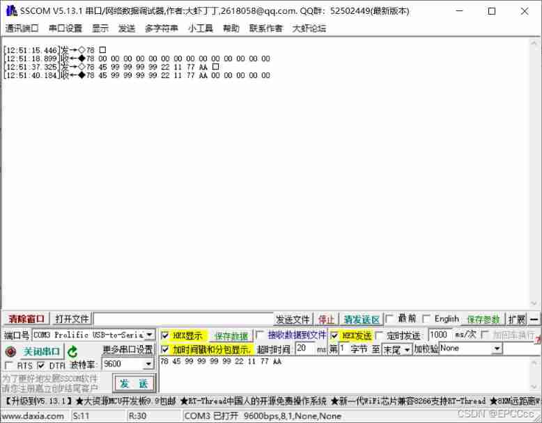
7、 ... and 、 summary
This i2c It also took me a lot of time to debug the module , Be sure to take a good look at the manual , It's high byte MSB Or low byte LSB
边栏推荐
- JVM命令之- jmap:导出内存映像文件&内存使用情况
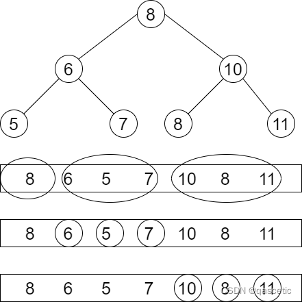
- Question 102: sequence traversal of binary tree
- 职场经历反馈给初入职场的程序员
- yarn入门(一篇就够了)
- ML's shap: Based on the adult census income binary prediction data set (whether the predicted annual income exceeds 50K), use the shap decision diagram combined with the lightgbm model to realize the
- Jmeter自带函数不够用?不如自己动手开发一个
- Rk3399 platform development series explanation (WiFi) 5.52. Introduction to WiFi framework composition
- How much do you know about clothing ERP?
- 【FPGA教程案例14】基于vivado核的FIR滤波器设计与实现
- 牙齿干细胞的存储问题(未完待续)
猜你喜欢
Jinfo of JVM command: view and modify JVM configuration parameters in real time

Why does the data center need a set of infrastructure visual management system
Nvisual network visualization
PTA ladder game exercise set l2-004 search tree judgment
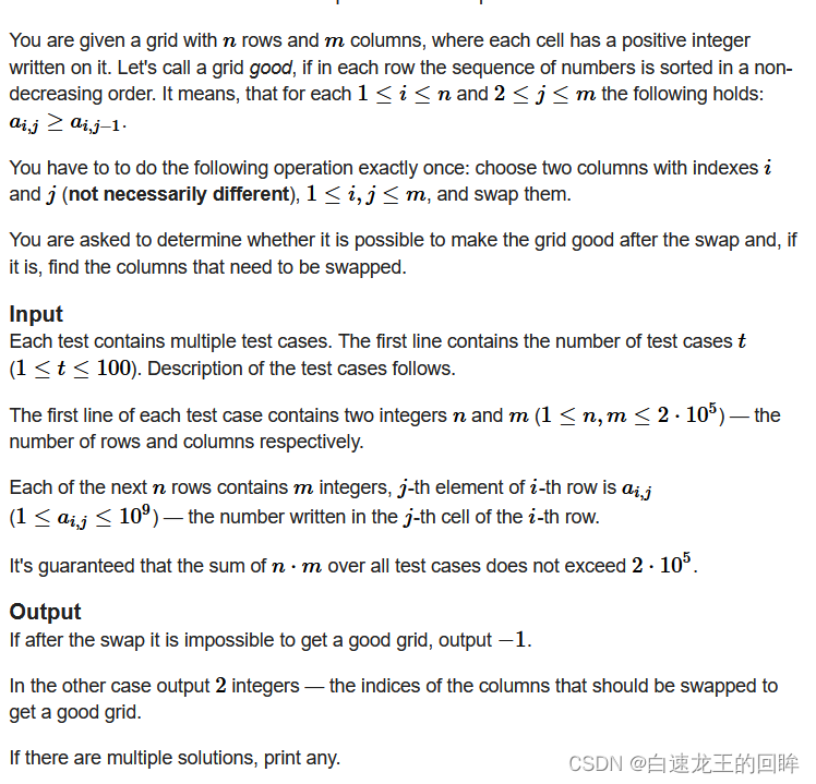
cf:C. Column Swapping【排序 + 模拟】
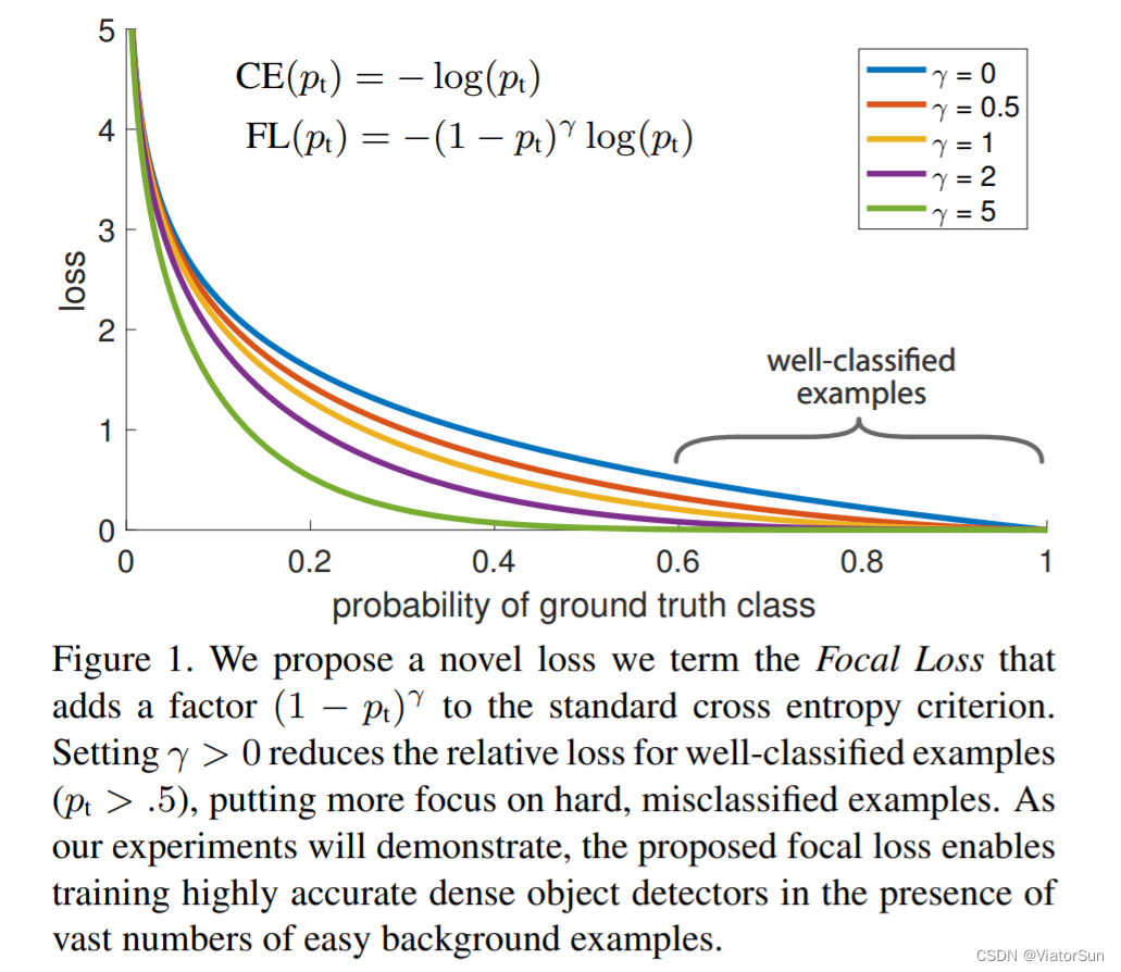
「解析」FocalLoss 解决数据不平衡问题
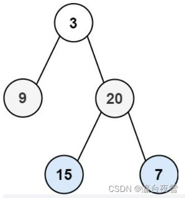
Question 102: sequence traversal of binary tree
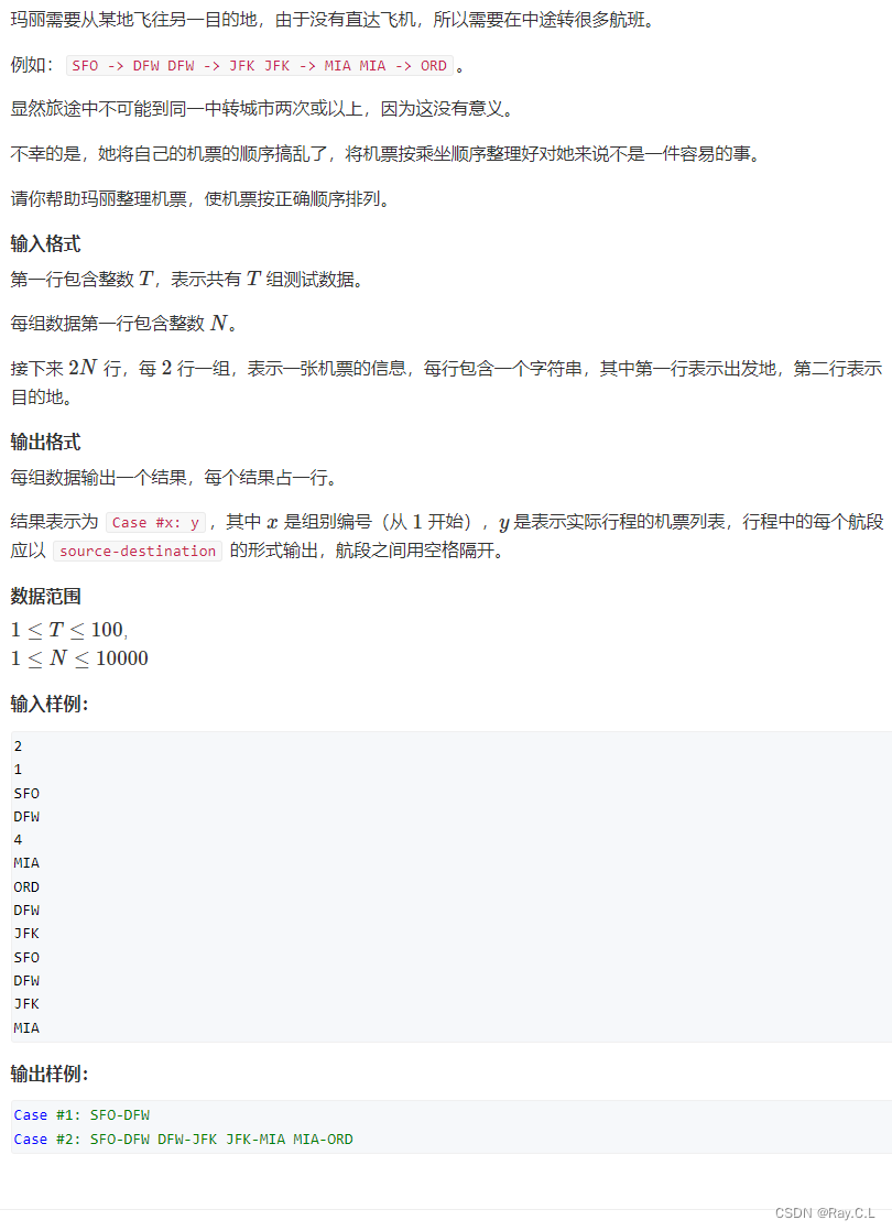
693. Travel sequencing
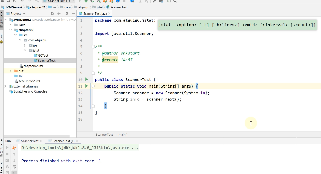
JVM命令之 jstat:查看JVM統計信息
Interview questions and salary and welfare of Shanghai byte

随机推荐
云加速,帮助您有效解决攻击问题!
PTA TIANTI game exercise set l2-003 moon cake test point 2, test point 3 Analysis
[Shell]常用shell命令及测试判断语句总结
Introduction to yarn (one article is enough)
[云原生]微服务架构是什么?
Data storage 3
每秒10W次分词搜索,产品经理又提了一个需求!!!(收藏)
Laravel uses Tencent cloud cos5 full tutorial
如何在Touch Designer 2022版中设置解决Leap Motion不识别的问题?
MySQL performance_ Schema common performance diagnosis query
Storage of dental stem cells (to be continued)
Vscode for code completion
You don't know the complete collection of recruitment slang of Internet companies
JVM命令之 jinfo:实时查看和修改JVM配置参数
[FPGA tutorial case 14] design and implementation of FIR filter based on vivado core
PTA 天梯赛练习题集 L2-002 链表去重
Jcmd of JVM command: multifunctional command line
【GNN】图解GNN: A gentle introduction(含视频)
CTFshow--常用姿势
Flask1.1.4 Werkzeug1.0.1 源碼分析:啟動流程