当前位置:网站首页>QT serial 4: LORA test platform based on QT and STM32H750 (3)
QT serial 4: LORA test platform based on QT and STM32H750 (3)
2022-07-30 07:15:00 【transparent light】
前言
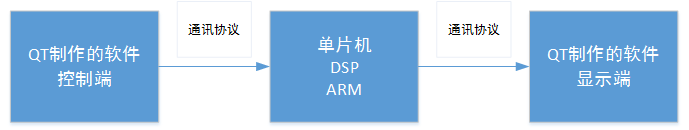
前面已经介绍了QT的制作,It includes three parts: transceiver and configuration.下面介绍STM32H750的程序架构.
First, the structure of the program is roughly divided into3个部分:
第一部分:According to the transceiver mechanism,H750接收串口(Call it that for now,这样好区分)将QTsent data received,Remove headers,提取数据,Then send it through the serial port1发送给LORA1.
第二部分:LORA1发送后,LORA2接收,通过LORA2the receiving serial port,将数据保存.
第三部分:将LORA2Received data is added to the header,通过LORA2The sending serial port is passed toQT,之后再QT中显示.
由于QTSome have already been detailed in the previous section,Except nowQT的剩下部分.
第一部分:初始化
UART_HandleTypeDef UART1_Handler; //UART¾ä±ú
DMA_HandleTypeDef  UART1TxDMA_Handler;      //DMA¾ä±ú

void UART1_Init(u32 bound)
{
	//UART ³õʼ»¯ÉèÖÃ
	UART1_Handler.Instance=USART1;					    //USART1
	UART1_Handler.Init.BaudRate=bound;				    //²¨ÌØÂÊ
	UART1_Handler.Init.WordLength=UART_WORDLENGTH_8B;   //×Ö³¤Îª8λÊý¾Ý¸ñʽ
	UART1_Handler.Init.StopBits=UART_STOPBITS_1;	    //Ò»¸öֹͣλ
	UART1_Handler.Init.Parity=UART_PARITY_NONE;		    //ÎÞÆæżУÑéλ
	UART1_Handler.Init.HwFlowCtl=UART_HWCONTROL_NONE;   //ÎÞÓ²¼þÁ÷¿Ø
	UART1_Handler.Init.Mode=UART_MODE_TX_RX;		    //ÊÕ·¢Ä£Ê½
	HAL_UART_Init(&UART1_Handler);					    //HAL_UART_Init()»áʹÄÜUART1

	HAL_UART_Receive_IT(&UART1_Handler, (u8 *)aRxBuffer, RXBUFFERSIZE);
}
一块一块解释:
Define the serial port interrupt,定义发送DMA中断;
串口初始化函数
The middle part is the definition of serial port:串口1、波特率等等,This part does not need to be changed
最后一句:Put the received interrupted data inbuffer里面,定义buffer数,这里定义为1个.
void MYDMA1_Config(void)
{
__HAL_RCC_DMA2_CLK_ENABLE();//DMA2ʱÖÓʹÄÜ
__HAL_LINKDMA(&UART1_Handler,hdmatx,UART1TxDMA_Handler);
UART1TxDMA_Handler.Instance=DMA2_Stream5; //Êý¾ÝÁ÷Ñ¡Ôñ
UART1TxDMA_Handler.Init.Request=DMA_REQUEST_USART1_TX; //USART1·¢ËÍDMA
UART1TxDMA_Handler.Init.Direction=DMA_MEMORY_TO_PERIPH; //´æ´¢Æ÷µ½ÍâÉè
UART1TxDMA_Handler.Init.PeriphInc=DMA_PINC_DISABLE; //ÍâÉè·ÇÔöÁ¿Ä£Ê½
UART1TxDMA_Handler.Init.MemInc=DMA_MINC_ENABLE; //´æ´¢Æ÷ÔöÁ¿Ä£Ê½
UART1TxDMA_Handler.Init.PeriphDataAlignment=DMA_PDATAALIGN_BYTE;
UART1TxDMA_Handler.Init.MemDataAlignment=DMA_MDATAALIGN_BYTE;
UART1TxDMA_Handler.Init.Mode=DMA_NORMAL; //ÍâÉèÁ÷¿Øģʽ
UART1TxDMA_Handler.Init.Priority=DMA_PRIORITY_MEDIUM; //ÖеÈÓÅÏȼ
UART1TxDMA_Handler.Init.FIFOMode=DMA_FIFOMODE_DISABLE;
UART1TxDMA_Handler.Init.FIFOThreshold=DMA_FIFO_THRESHOLD_FULL;
UART1TxDMA_Handler.Init.MemBurst=DMA_MBURST_SINGLE;
UART1TxDMA_Handler.Init.PeriphBurst=DMA_PBURST_SINGLE;
HAL_DMA_DeInit(&UART1TxDMA_Handler);
HAL_DMA_Init(&UART1TxDMA_Handler);
}
void DMA2_Stream5_IRQHandler(void)
{
HAL_DMA_IRQHandler(&UART1TxDMA_Handler);
}
void USART1_IRQHandler(void)
{
HAL_UART_IRQHandler(&UART1_Handler); //µ÷ÓÃHAL¿âÖжϴ¦Àí¹«Óú¯Êý
} 此处为定义DMA初始化,DMA中断入口,没有中断处理函数.串口1中断入口.
void HAL_UART_MspInit(UART_HandleTypeDef *huart)
{
GPIO_InitTypeDef GPIO_Initure;
if(huart->Instance==USART1)//Èç¹ûÊÇ´¿Ú1£¬½øÐд¿Ú1 MSP³õʼ»¯
{
__HAL_RCC_GPIOA_CLK_ENABLE(); //ʹÄÜGPIOAʱÖÓ
__HAL_RCC_USART1_CLK_ENABLE(); //ʹÄÜUSART1ʱÖÓ
GPIO_Initure.Pin=GPIO_PIN_9; //PA9
GPIO_Initure.Mode=GPIO_MODE_AF_PP; //¸´ÓÃÍÆÍìÊä³ö
GPIO_Initure.Pull=GPIO_PULLUP; //ÉÏÀ
GPIO_Initure.Speed=GPIO_SPEED_FREQ_HIGH;//¸ßËÙ
GPIO_Initure.Alternate=GPIO_AF7_USART1; //¸´ÓÃΪUSART1
HAL_GPIO_Init(GPIOA,&GPIO_Initure); //³õʼ»¯PA9
GPIO_Initure.Pin=GPIO_PIN_10; //PA10
HAL_GPIO_Init(GPIOA,&GPIO_Initure); //³õʼ»¯PA10
HAL_NVIC_EnableIRQ(USART1_IRQn); //ʹÄÜUSART1ÖжÏͨµÀ
HAL_NVIC_SetPriority(USART1_IRQn,3,3); //ÇÀÕ¼ÓÅÏȼ¶3£¬×ÓÓÅÏȼ¶3
HAL_NVIC_SetPriority(DMA2_Stream5_IRQn, 3, 4);
HAL_NVIC_EnableIRQ(DMA2_Stream5_IRQn);
}
}Here is the automatic calling function for serial port initialization,If serial port is defined1,Then this function will be called directly,It defines the pin type,中断类型,As well as binding serial ports and DMA.
第二部分:中断函数
void HAL_UART_RxCpltCallback(UART_HandleTypeDef *huart)
{
	if(huart->Instance==USART1)//Èç¹ûÊÇ´¿Ú1
	{

		HostSpareSetData();

    HAL_UART_Receive_IT(&UART1_Handler, (u8 *)aRxBuffer, RXBUFFERSIZE);
	}
}
Here is the serial port receiving interrupt.并配合HostSpareSetData()函数使用.
void HostSpareSetData(void)
{
		nSciaRxBuffer[nSciaRxBufHead]=aRxBuffer[0];
		nSciaRxBufHead++;
		if(nSciaRxBufHead>=SCIA_RX_BUF_SIZE)	nSciaRxBufHead=0;
		if(nSciaRxBufHead==nSciaRxBufTail)
		{
			nSciaRxBufTail++;
			if(nSciaRxBufTail>=SCIA_RX_BUF_SIZE)	nSciaRxBufTail=0;
		}
}
This function is after the serial port has data,进入中断,will interrupt the databuffercontent into onefifo里面.然后再解析fifo.
第三部分:while执行
void HostSpareSetDataDeal(void)
{
	int i=0;
	nSciaRxLengthTemp = nSciaRxBufHead - nSciaRxBufTail;
	if( nSciaRxLengthTemp < 0 ) nSciaRxLengthTemp = nSciaRxLengthTemp+ SCIA_RX_BUF_SIZE;

	switch( nSciaRxCtrlMode )
	{
		case MODE_SCIARXCMD_WAIT:
			nSciaRxVerify = 0xFFFF;
			if( nSciaRxLengthTemp >= 8 )
			{
				nSciaRxHeadCheck = SciaRdCharRxBuff();
				if( nSciaRxHeadCheck == 0x03 )
				{
          nSciaRxCtrlMode = MODE_SCIARX_LORA1;
				}
				if( nSciaRxHeadCheck == 0x04 )
				{
          nSciaRxCtrlMode = MODE_SCIARX_LORA2;
				}
			}
		break;
		case MODE_SCIARX_LORA1:
			  nSciaRxOrder = SciaRdCharRxBuff();
				if( nSciaRxOrder == 0x06 )
				{
          nSciaRxCtrlMode = MODE_SCIARX_LORA1_INIT;
				}
				if( nSciaRxOrder == 0x10 )
				{
					nSciaRxID = SciaRdWordRxBuff();
		      nSciaRxDataLength = SciaRdWordRxBuff();
          nSciaRxCtrlMode = MODE_SCIARX_LORA1_SEND;
				}
		break;
		case MODE_SCIARX_LORA2:
			  nSciaRxOrder = SciaRdCharRxBuff();
				if( nSciaRxOrder == 0x06 )
				{
          nSciaRxCtrlMode = MODE_SCIARX_LORA2_INIT;
				}
				if( nSciaRxOrder == 0x10 )
				{
					nSciaRxID = SciaRdWordRxBuff();
		      nSciaRxDataLength = SciaRdWordRxBuff();
          nSciaRxCtrlMode = MODE_SCIARX_LORA2_SEND;
				}
		break;
}
此部分在while里面执行,具体流程为:Interrupt counts,Parse the data here.其中03和04代表不同的LORA发送的数据.For details, see the communication protocol in the previous article.After parsing the data,再添加对应的case,Different data can be processed.
		case MODE_SCIARX_LORA1_SEND:
			  if( nSciaRxLengthTemp >= (nSciaRxDataLength+2) )
			  {
					for(i=0;i<nSciaRxDataLength;i++)
					{
					  nSciaRxData[i+3] = SciaRdCharRxBuff();
					}
					nSciaRxVerifyTemp = nSciaRxVerify;
				  nSciaRxCheck = SciaRdWordRxBuff();
				  nSciaRxVerifyTemp = HLChange(nSciaRxVerifyTemp);
				  if(nSciaRxVerifyTemp == nSciaRxCheck)
				  {
						nSciaRxData[0] = 0x5A;
						nSciaRxData[1] = 0xA5;
						nSciaRxData[2] = nSciaRxDataLength;

						nSciaTxVerify = 0xFFFF;
						for(i=0;i<nSciaRxDataLength+3;i++)
						{
						  nSciaTxVerify = GetCRC16(nSciaRxData[i], nSciaTxVerify);
						}
						nSciaRxData[nSciaRxDataLength+3] = nSciaTxVerify&0x00FF;
						nSciaRxData[nSciaRxDataLength+4] = (nSciaTxVerify&0xFF00)>>8;

						HAL_UART_Transmit_DMA(&UART7_Handler,nSciaRxData,nSciaRxDataLength+5);
					}
					nSciaRxCtrlMode = MODE_SCIARXCMD_WAIT;
				}
		break;
		case MODE_SCIARX_LORA2_SEND:
			  if( nSciaRxLengthTemp >= (nSciaRxDataLength+2) )
			  {
					for(i=0;i<nSciaRxDataLength;i++)
					{
					  nSciaRxData[i+3] = SciaRdCharRxBuff();
					}
					nSciaRxVerifyTemp = nSciaRxVerify;
				  nSciaRxCheck = SciaRdWordRxBuff();
				  nSciaRxVerifyTemp = HLChange(nSciaRxVerifyTemp);
				  if(nSciaRxVerifyTemp == nSciaRxCheck)
				  {
						nSciaRxData[0] = 0x5A;
						nSciaRxData[1] = 0xA5;
						nSciaRxData[2] = nSciaRxDataLength;

						nSciaTxVerify = 0xFFFF;
						for(i=0;i<nSciaRxDataLength+3;i++)
						{
						  nSciaTxVerify = GetCRC16(nSciaRxData[i], nSciaTxVerify);
						}
						nSciaRxData[nSciaRxDataLength+3] = nSciaTxVerify&0x00FF;
						nSciaRxData[nSciaRxDataLength+4] = (nSciaTxVerify&0xFF00)>>8;


						HAL_UART_Transmit_DMA(&UART4_Handler,nSciaRxData,nSciaRxDataLength+5);
					}
					nSciaRxCtrlMode = MODE_SCIARXCMD_WAIT;
				}
		break;
Added herecase,When the previously parsed data is parsed,can enter thiscase了,That is to enter this state machine.进入后,处理数据,Then send the corresponding send data.
HAL_UART_Transmit_DMA(&UART4_Handler,nSciaRxData,nSciaRxDataLength+5);This is the send function.
第四部分:总结
The send function is relatively simple,Just the last sentence above,Put the data away,put the length,The serial port interrupt entry is selected,就可以直接发送了.
The receive function is more cumbersome.The step is to put the receive data in the interruptbuffer,再放进fifo,Then parse the data in a loop,Then make a step-by-step jump.This parses the data and sends the data that should be sent logically.
The above program is only a part of the interception,But most of the logic is there,Put it in and add relevant definitions,就能正确运行了.If you need source code,You can scan the subscription number below,I'll put the full code in there then,If you have any questions, you can leave a message,Will be patient to explain.

边栏推荐
- 边境的悍匪—机器学习实战:第十三章 使用TensorFlow加载和预处理数据
- Kunlun State Screen Production (Serialization 5) --- Basics (serial port reception, text and light display)
- Knowledge distillation method of target detection
- 无人机生态环境监测、图像处理与GIS数据分析
- FPGA解析B码----连载1
- 动态规划进阶 JS
- [Jiangsu University Automation Association stm32F103c8t6] Notes [Initial 32 MCU and EXTI External Interrupt Initialization Parameter Configuration]
- 边境的悍匪—机器学习实战:第六章 决策树
- Rsync realizes folder or data synchronization between Win systems
- 逻辑右移和算术右移区别
猜你喜欢

【江科大自化协stm32F103c8t6】笔记之【入门32单片机及TIM定时中断初始化参数配置】

FPGA解析B码----连载2

大气颗粒物 PMF 源解析

QT连载3:基于QT和STM32H750的LORA试验平台(2)

DeepLearing4j's deep learning Yolo Tiny realizes target detection

Knowledge distillation method of target detection

边境的悍匪—机器学习实战:第十二章 使用TensorFlow自定义模型和训练

QT每周技巧(1)~~~~~~~~~运行图标
QT serial and CAN dynamic real-time display the log data

求职准备知识点
随机推荐
jvm之逃逸分析
无人机生态环境监测、图像处理与GIS数据分析
经典排序之插入排序
基于MATLAB 2021b的机器学习、深度学习
QT串口动态实时显示大量数据波形曲线(五)========“最终完美解决版”
边境的悍匪—机器学习实战:第十六章使用RNN和注意力机制进行自然语言处理
新导则下 防洪评价报告编制方法及洪水建模(HEC-RAS)
openssl 1.1.1 compile statement
动态规划入门 JS
信号链模拟芯片是什么?
JS的值和引用,复制和传递
暂时存着阿里云
动态规划进阶 JS
2021 soft exam intermediate pass
How does MATLAB display nii file slice information in the image?
闭包(你不知道的JS)
OpenCV中(rows,cols)与图像(x,y)
QT连载1:readyRead()函数,数据分包不完整解决办法
[Jiangsu University Self-Chemistry Association stm32F103c8t6] Notes [Entry 32 MCU and GPIO initialization parameter configuration]
Antd简单启动一个企业级项目