当前位置:网站首页>Design and Simulation of direct torque control system for induction motor (motion control matlab/simulink)
Design and Simulation of direct torque control system for induction motor (motion control matlab/simulink)
2022-06-27 10:15:00 【Chloroplasts do not forget to breathe】
WeChat official account : Chuangxiang diary
Send keywords : Direct torque
Get the full report for free +matlab/simulink Simulation source file
1 introduction
Direct torque control (DTC) Technology is the upgrade of vector control technology , It is a novel variable frequency speed regulation technology , from 1980 year M.Depenbrock and I.Takahashi Begin to put forward the theory , To 90 years Zhong.L, Rahman M F, Hu Y W Et al. Put forward the theory of direct torque control , It is applied to the control of asynchronous motor , The motor control is mainly realized through flux closed loop and torque closed loop , So as to achieve similar control characteristics with DC motor .
20 century ,M.Depenbrock The professor has put forward and continuously studied the theory and method of direct torque control asynchronous motor , At the same time, the control of flux and torque is realized . With the continuous spread of his theory , The control technology and method have been developed rapidly .
After this , Japan's Takahashi On the basis of torque control theory, scholars put forward the control theory of flux linkage trajectory , Make the motion track of the flux vector approach to circular motion , At the same time, the accuracy and stability of asynchronous motor control are continuously improved .
2 System structure design and principle analysis
Based on the switching characteristics of voltage source inverter , Under the condition of changing the voltage state, the running track of the stator flux linkage tends to be hexagonal or approximately circular , With the constant insertion of zero voltage vector, the slip frequency changes constantly , So as to further control the constant change of motor torque and flux linkage . Thus, the asynchronous motor can respond to the changes of flux linkage and torque in time . The core function of the asynchronous motor control system is to control the flux linkage and torque through the transformation of the flux angle , The output torque of the motor changes strictly according to the given value of the input torque .
The principle structure diagram of the direct torque control system is shown in the figure 2-1 Shown , In the figure ASR、AFR and ATR They are speed regulators 、 Stator flux regulator and torque regulator . Speed regulator ASR use PI Regulator , Stator flux regulator AFR A two position controller with hysteresis loop is adopted , Torque regulator ATR A two position controller with hysteresis loop is adopted . In the figure , Stator flux is given ψ_s* It is related to the actual speed , Below rated speed ,ψ_s* Keep it constant , Above rated speed ,ψ_s^* It decreases as the actual speed increases .

2.1 Stator flux regulation
The conventional PID controller , Because of its PID The self-tuning of the parameters is very complex and tedious , And seriously affect the dynamic and static stability of the control system , Therefore, hysteresis comparator is selected to control the asynchronous motor , Its control block diagram is shown in Figure 2-2 Shown . The amplitude deviation of stator flux linkage can be expressed as △ψ_s=|ψ_s^* |-|ψ_s |, The deviation of stator flux amplitude is adjusted by hysteresis comparator , The control law is as follows :
1) When △ψ_s>c when ,Sign(△ψ_s )=1, Select the appropriate vector to increase the stator flux .
2) When △ψ_s<c when ,Sign(△ψ_s )=0, Select the appropriate vector to reduce the stator flux .
2.2 Electromagnetic torque regulation
In order to realize the direct control of torque , Torque adjustment is required . Its control block diagram is shown in Figure 2-3 Shown , To control the torque , The torque regulator must be able to 2 Features :
1) The torque regulator directly regulates the torque .
2) Adjust the rotation direction of the stator flux while adjusting the torque .
The electromagnetic torque deviation can be expressed as △T_e=|T_e^* |-|T_e |, The control law of torque regulation is as follows :
1) When △T_e>c_2 when ,Sign(△T_e )=1, The stator magnetic field rotates in a positive direction , Actual electromagnetic torque T_e enlarge .
2) When -c_1<△T_e<c_1 when ,Sign(△T_e )=0, The stator magnetic field stops rotating , Electromagnetic torque reduction .
3) When △T_e<-c_2 when ,Sign(△T_e )=-1, The stator field rotates in reverse , Actual electromagnetic torque T_e Reverse enlargement .
2.3 Voltage space vector selection
When the stator flux vector is at the Ⅰ At different positions in the sector , Press Sign(△ψ_s ) and Sign(△T_e ) Values are calculated by looking up tables , As shown in the table 2-1 Shown , Select voltage space vector , If there is conflict between flux control and torque control , Torque control is preferred , The zero vector can be selected according to the principle of minimum switching loss . The selection of voltage space vector of flux linkage in other sectors can be analogized .
3 System simulation model
3.1 Simulation model building and parameter design
The main parameters of the asynchronous motor of the system are as follows : The rated power is p_N=4000W, The rated voltage is U_N=400V, The rated frequency is f_N=50Hz, Rated speed n_N=1430rpm.
be based on Matlab/Simulink The simulation model of the direct torque control system of induction motor is shown in the figure 3-1 Shown , It mainly includes the following modules :
① Speed regulator ASR
② Stator flux regulator AFR
③ Torque regulator ATR
④3/2 Transformation link
⑤ Stator flux calculation link
⑥ Torque calculation link
⑦ Voltage vector selection link
⑧ Three phase full bridge inverter 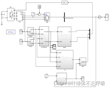
3.2 Speed regulator ASR
The deviation obtained by comparing the speed setting value with the current speed feedback value is sent to PI In the regulator to adjust the output of the corresponding T_e^*.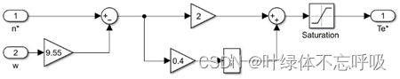
3.3 Stator flux regulator AFR
Compare with the stator flux setting , Calculate the stator flux linkage deviation △ψ_s. In addition, it is necessary to calculate the position of the current stator flux linkage , Here we use a S-Function To calculate the position of the current stator flux linkage .
(psi_to_fai See the wechat official account source file for the function )
3.4 Torque regulator ATR
By torque from T_e The current torque value is calculated in the calculation link T_e, And torque setting T_e^* Comparison , Then the torque deviation is obtained through the hysteresis controller △T_e.
3.5 3/2 Transformation link
This link is used to convert the three-phase static voltage and current of the current main circuit into two-phase static voltage and current respectively .

3.6 Stator flux calculation link
It is necessary to calculate the two components of the stator flux linkage in the static two-phase coordinate system according to the voltage model .
3.7 Torque calculation link
According to the expression of electromagnetic torque in the static two-phase coordinate system in the textbook, the corresponding electromagnetic torque is obtained T_e.
3.8 Voltage vector selection link
Calculated stator flux linkage deviation △ψ_s, Torque deviation △T_e, And the position of the current stator flux linkage as input , To design a S-Function( See the wechat official account source file for details ) Calculation 6 Selection of three voltage space vectors , And then input it to IGBT Control end of inverter bridge .
3.9 Three phase full bridge inverter
The three-phase full bridge inverter circuit is selected as the inverter .
4 System simulation results and analysis
4.1 The given speed is 1000rpm, The load is 5

4.2 The given speed is 600rpm, The load is 5

4.3 The given speed is 1400rpm, The load is 5( The sampling period is 0.2)

4.4 The given speed is 1000rpm, The load is 0

4.5 The given speed is 1000rpm, The load is 20

4.6 Flux linkage pattern 
5 Conclusion
The design detects the output phase voltage and phase current , The stator torque and flux linkage are obtained through transformation and calculation in the static and rotating coordinate systems , And pass Matlab/Simulink Build a simulation model , It mainly embodies the control idea and theory of direct torque , Through calculation and summary, the data of stator flux and torque are obtained , Then the flux linkage and torque are controlled , The simulation results show that : The control system has good dynamic and static stability .
Zai Jing PI Under the function of adjustment, the effect picture of the start-up stage is enlarged , Therefore, the torque is amplified to varying degrees , Thus, the rotating speed increases continuously and reaches a balance state soon , So when the speed reaches equilibrium , The torque has reached the balance stage .
Change the load torque , When the motor is in balance, the torque becomes larger , Thus, the starting time of asynchronous motor becomes longer .
6 Comprehensive design experience
Because of its fast action speed, asynchronous motor , High efficiency is widely used , But the control method also has higher requirements , With the appearance of direct torque control method , It makes the application of variable frequency speed regulation in the field of asynchronous motor more extensive and in-depth .
Through the course design of motion control system, induction motor direct torque control system , I have not only deepened my understanding of AC asynchronous motor control theory , Apply theory to practice better , And I also learned how to cultivate the spirit of innovation , So as to constantly overcome themselves .
The course design makes me have a deep understanding of DTC , At ordinary times, we seldom touch the actual high-power motor in the production process , So its control is relatively strange . Access to information , Collected a lot of knowledge about AC asynchronous motor control .
边栏推荐
- R language plot visualization: visualize the normalized histograms of multiple data sets, add density curve KDE to the histograms, set different histograms to use different bin sizes, and add edge whi
- 细说物体检测中的Anchors
- Flutter wechat sharing
- 分布式文件存储系统的优点和缺点
- border影响父元素的高度-解决方案
- unity--newtonsoft.json解析
- 产品力对标海豹/Model 3,长安深蓝SL03预售17.98万起
- TDengine 邀请函:做用技术改变世界的超级英雄,成为 TD Hero
- js的数组拼接「建议收藏」
- When does the mobile phone video roll off?
猜你喜欢

Product strength benchmarking seal /model 3, with 179800 pre-sales of Chang'an dark blue sl03

Use aspese slides to convert PPT to PDF
![[200 opencv routines] 212 Draw a slanted rectangle](/img/cf/da8fff386d011c939946326c55671f.png)
[200 opencv routines] 212 Draw a slanted rectangle

This application failed to start because it could not find or load the QT platform plugin

【OpenCV 例程200篇】211. 绘制垂直矩形

通俗易懂理解樸素貝葉斯分類的拉普拉斯平滑

手机影像内卷几时休?

细说物体检测中的Anchors

LVI Sam summary

多线程实现 重写run(),怎么注入使用mapper文件操作数据库
随机推荐
torchvision. models._ utils. Intermediatelayergetter tutorial
有关WIN10的内存压缩
Technology is as important as business. It is wrong to favor either side
Curiosity mechanism in reinforcement learning
邮件系统(基于SMTP协议和POP3协议-C语言实现)
Mongodb cross host database copy and common commands
R language uses econcharts package to create microeconomic or macro-economic charts, demand function to visualize demand curve, and customize the parameters of demand function to enrich the visualizat
3D移动 translate3d
JS array splicing "suggested collection"
Comparison between new and old interfaces
This application failed to start because it could not find or load the QT platform plugin
Freemarker
软交换呼叫中心系统的支撑系统
谷歌浏览器 chropath插件
迪米特法则
2021 CSP J2 entry group csp-s2 improvement group round 2 video and question solution
小哥凭“量子速读”绝技吸粉59万:看街景图0.1秒,“啪的一下”在世界地图精准找到!...
border影响父元素的高度-解决方案
. Net
For a moment, the ban of the US e-cigarette giant has been postponed, and products can be sold in the US for the time being