当前位置:网站首页>Unity shader learning (3) try to draw a circle
Unity shader learning (3) try to draw a circle
2022-07-04 14:06:00 【ToDoNothing】
On the first code
Shader "Unlit/shader4"
{

    Properties
    {


    }
    SubShader
    {

        Tags {
     "RenderType"="Opaque" }
        LOD 100

        Pass
        {

            CGPROGRAM
            #pragma vertex vert
            #pragma fragment frag


            #include "UnityCG.cginc"
        struct v2f{

            float4 vertex:SV_POSITION;
            float4 position:TEXCOORD1;
            float2 uv:TEXCOORD0;
        };
        v2f vert(appdata_base v){

            v2f o;
            o.vertex=UnityObjectToClipPos(v.vertex);
            o.position=v.vertex;
            o.uv=v.texcoord;
            return o;
        }

        float circle(float2 uv,float2 center){

            float2 offset=uv-center;
            float len=length(offset);
            return step(len,0.2)-step(len,0.19);
        }


            fixed4 frag (v2f i) : SV_Target
            {

               fixed4 col=circle(i.uv,float2(0.5,0.5));
                return col;
            }
            ENDCG
        }
    }
}
Here's an explanation
According to the second tutorial , We are Pass Two processing flows are defined in the block , Respectively vertex and fragment, Execute first vertex Vertex shader , Processing vertex information , Proceed again fragment Chip shader , Deal with color, illumination and other information . So we define a structure at the top , Information used to define a vertex :
   struct v2f{

            float4 vertex:SV_POSITION;
            float4 position:TEXCOORD1;
            float2 uv:TEXCOORD0;
        };
You can see , The defined structure contains two Texcoord, Texture information , Only two groups are read here . In addition to that SV_POSITION Is the position of the vertex , except SV_POSITION, There is another parameter called POSITION, There is not much difference between the two , As follows :
POSITION: Used to store , Model in local coordinates , In model space (objcet space) The coordinates of the vertices of , Coordinates before converting to clipping space coordinates ,unity Tell our model vertex coordinates , Not converted . Can be used as vertex shader (vertex shader) The input of 、 Output ; Chip shader (frag) The input of .
SV_POSITION: Used to store , The model is in the clipping space , Location information in projection space , That is, the fixed-point coordinates of the model space , Convert to the coordinates of the clipping space , Can be used as vertex shader (vertex shader) Output ; Chip shader (frag) The input of .
Next is the processing of vertex shaders , namely vert function , Corresponding to the above #pragma vertex Name , As shown below , Input appdata_base For defined built-in variables , Never mind , The whole function returns a structure , Internal variables have been re assigned .
Such as o.vertex, Through the built-in conversion function UnityObjectToClipPos, Model space , Convert to cutting space . About model space 、 The concept of cutting space , Reference resources Render several basic coordinate spaces in the pipeline ( Object space 、 World space 、 Camera space ( Observe the space )、NDC Space 、 Cutting space 、 Screen space )
   v2f vert(appdata_base v){

            v2f o;
            o.vertex=UnityObjectToClipPos(v.vertex);
            o.position=v.vertex;
            o.uv=v.texcoord;
            return o;
        }
When it's done , Handle the slice shader
   fixed4 frag (v2f i) : SV_Target
            {

               fixed4 col=circle(i.uv,float2(0.5,0.5));
                return col;
            }
The slice shader just runs a function , Color the current point , So let's look at this function
   float circle(float2 uv,float2 center){

            float2 offset=uv-center;
            float len=length(offset);
            return step(len,0.2)-step(len,0.19);
        }
circle Function has parameters and return values , Input two coordinate information , One is the coordinates of the vertex , One is the center point of the circle , First , Calculate the distance between the vertex coordinate and the center point coordinate , Reuse step Function to process .
step The logic of the function is as follows :
step (a, b)
{

  if (a > b)
  {

    return 0;
  }
  else
  {

    return 1;
  }
}
therefore , Its principle is to judge the distance between the current point and the central point , Whether it is within the appropriate range , If in , return 1, Indicates that colors can be filled , Here I use two step function , Make him form a circle , In this range , Just display the color , As shown in the figure below . Two Step Subtracting the , You can judge whether it is within this range .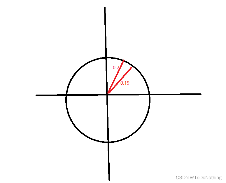
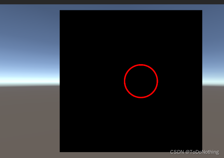
The specific effect is as follows :
If you want to change the color , Radius and center , The code is as follows
Shader "Unlit/shader4"
{

    Properties
    {

    _Radius("Radius",Float)=0.1
    _Center("Center",Vector)=(0.5,0.5,0,0)
    _LineColor("LineColor",Color)=(1,1,1,1)
    }
    SubShader
    {

        Tags {
     "RenderType"="Opaque" }
        LOD 100

        Pass
        {

            CGPROGRAM
            #pragma vertex vert
            #pragma fragment frag


            #include "UnityCG.cginc"
        struct v2f{

            float4 vertex:SV_POSITION;
            float4 position:TEXCOORD1;
            float2 uv:TEXCOORD0;
        };
        v2f vert(appdata_base v){

            v2f o;
            o.vertex=UnityObjectToClipPos(v.vertex);
            o.position=v.vertex;
            o.uv=v.texcoord;
            return o;
        }
        float _Radius;
        float4 _Center;
        fixed4 _LineColor;
        float circle(float2 uv,float2 center){

            float2 offset=uv-center;
            float len=length(offset);
            return step(len,_Radius+0.01)-step(len,_Radius);
        }


            fixed4 frag (v2f i) : SV_Target
            {

                float2 center=float2(_Center.x,_Center.y);
               fixed4 col=circle(i.uv,center)*_LineColor;
                return col;
            }
            ENDCG
        }
    }
}
The effect is as follows 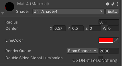
边栏推荐
- 面试官:Redis中哈希数据类型的内部实现方式是什么?
- 30: Chapter 3: develop Passport Service: 13: develop [change / improve user information, interface]; (use * * * Bo class to accept parameters, and use parameter verification)
- C语言中学生成绩管理系统
- Worried about "cutting off gas", Germany is revising the energy security law
- 免费、好用、强大的轻量级笔记软件评测:Drafts、Apple 备忘录、Flomo、Keep、FlowUs、Agenda、SideNote、Workflowy
- JVM memory layout detailed, illustrated, well written!
- Huahao Zhongtian sprint Technology Innovation Board: perte annuelle de 280 millions de RMB, projet de collecte de fonds de 1,5 milliard de Beida Pharmaceutical est actionnaire
- Ruichengxin micro sprint technology innovation board: annual revenue of 367million, proposed to raise 1.3 billion, Datang Telecom is a shareholder
- JVM series - stack and heap, method area day1-2
- 德明利深交所上市:市值31亿 为李虎与田华夫妻档
猜你喜欢

markdown 语法之字体标红

数据库公共字段自动填充

華昊中天沖刺科創板:年虧2.8億擬募資15億 貝達藥業是股東
Flet tutorial 03 basic introduction to filledbutton (tutorial includes source code) (tutorial includes source code)
Unittest中的TestSuite和TestRunner

面试官:Redis中哈希数据类型的内部实现方式是什么?

Automatic filling of database public fields
1200. Minimum absolute difference

Unity Shader学习(三)试着绘制一个圆

2022 Shandong Province safety officer C certificate examination question bank and online simulation examination
随机推荐
E-week finance | Q1 the number of active people in the insurance industry was 86.8867 million, and the licenses of 19 Payment institutions were cancelled
1200. 最小绝对差
Fisher信息量检测对抗样本代码详解
华昊中天冲刺科创板:年亏2.8亿拟募资15亿 贝达药业是股东
Unittest框架中引入TestFixture
go vendor 项目迁移到 mod 项目
德明利深交所上市:市值31亿 为李虎与田华夫妻档
392. 判断子序列
JVM series - stack and heap, method area day1-2
Huahao Zhongtian sprint Technology Innovation Board: perte annuelle de 280 millions de RMB, projet de collecte de fonds de 1,5 milliard de Beida Pharmaceutical est actionnaire
gorm 之数据插入(转)
30: Chapter 3: develop Passport Service: 13: develop [change / improve user information, interface]; (use * * * Bo class to accept parameters, and use parameter verification)
ViewBinding和DataBinding的理解和区别
2022g3 boiler water treatment examination question simulation examination question bank and simulation examination
国内酒店交易DDD应用与实践——代码篇
【C 题集】of Ⅶ
吃透Chisel语言.08.Chisel基础(五)——Wire、Reg和IO,以及如何理解Chisel生成硬件
基于PaddleX的智能零售柜商品识别
MySQL 5 installation and modification free
Redis —— How To Install Redis And Configuration(如何快速在 Ubuntu18.04 与 CentOS7.6 Linux 系统上安装 Redis)