当前位置:网站首页>[Arduino uses a rotary encoder module]
[Arduino uses a rotary encoder module]
2022-08-02 04:32:00 【WENJIE Technology】
ArduinoUse a rotary encoder module
前言
A rotary encoder is an electromechanical position sensor,Can be used to identify the angular position of an axis of rotation.This type of sensor or module generates electrical signals based on the motion and orientation of a rotating shaft.The encoder consists of mechanical parts,So the sensor is very robust,可用于许多应用,如机器人、计算机鼠标、CNC machines and printers.There are two types of rotary encoders:One is the absolute encoder,The other is an incremental encoder.
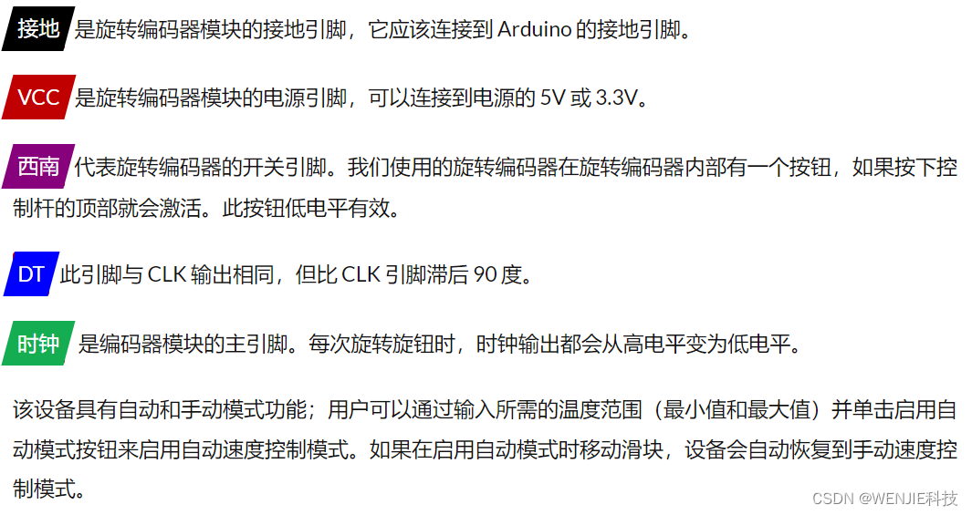
Rotary encoder module pins
Rotary encoder module has 5 个引脚;分别是 GND、+(VCC)、SW(Switch)、DT 和 CLK.All pins of this sensor module are digital,除了 VCC 和地.The pinout of the rotary encoder module is shown below:
How the rotary encoder module works?
If we remove the rotary encoder,We will see that there is a disc,There are many holes on it.The encoder board is connected to common ground,The two contacts are shown below.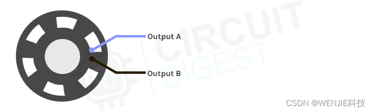 When the shaft of the encoder turns,输出 A 和输出 B The terminals make contact with the common board in a specific order,The exact order depends on the direction of rotation.If the encoder wheel rotates clockwise,输出 A will connect first,然后输出 B will be connected to the common board.If the encoder is rotated counterclockwise,则会发生相反的情况,但最终,输出 A 和输出 B The resulting signals will always be out of phase with each other 90*.
在上面的动画中,If we turn the shaft of the encoder clockwise,针脚A先连接,then pinB连接.By keeping track of which pin is connected first,We can determine the direction of rotation,So we can increase or decreaseaCount according to the direction of rotation.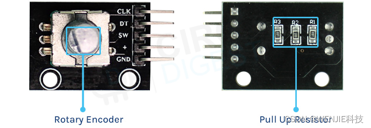 If you look closely at the rotary encoder module,PCB There isn't much in itself,在顶部,We have rotary encoders and header pins for connection,而在底部,We only have pull-up resistors.This makes up our entire rotary encoder module.Since a rotary encoder is a mechanical device,因此可以在 3.3V 和 5V work under working voltage.
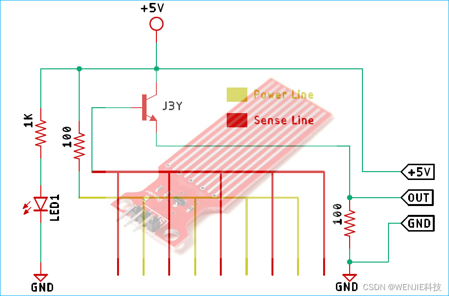
Rotary encoder module circuit diagram
The module is made of very versatile and ready-to-use components,You only need three resistors and the encoder itself to build it yourself.A schematic diagram of the rotary encoder module is shown below.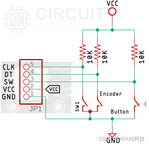
如上图所示,There isn't much in the rotary encoder module,只需要三个10KPull-up resistors to build your own modules.If you are building from modules PCB,Then this schematic can come in handy.
ArduinoRotary encoder module circuit connection diagram
Now we fully understand how the rotary encoder module works,We can connect all the necessary wires to Arduino And write the code to get all the angular position data from the sensor.Rotary encoder module with Arduino The connection diagram is shown below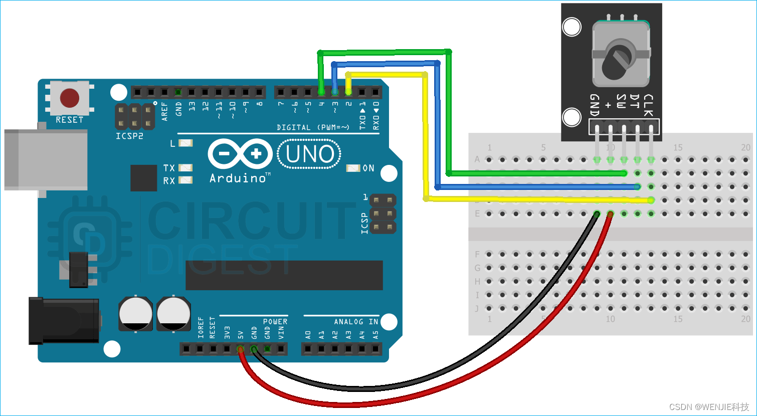 Connect the rotary encoder module to Arduino非常简单,We simply place the rotary encoderCLK和DT引脚连接到Arduino的外部中断引脚,即Arduino的D2和D3 in,我们需要连接SW引脚连接到 Arduino 的 D4 引脚,We configure it as a pin change interrupt pin.That's from the rotary encoder to Arduino the entire contents of the hardware connection,We can now move to the code section.
代码说明
Reads angle data from a rotary encoderArduino The rotary encoder code is shown below.代码非常简单易懂.对于此代码,We will use interrupts to get angle data from the rotary encoder.We use interrupts because there is very little chance of an interrupt going wrong.
We start our code by including all the required libraries,We also set the clock、Data and button pins are defined Arduino 引脚.
#include "PinChangeInterrupt.h"
#define CLK 2
#define DT 3
#define SW 4
接下来,We define all the variables needed to hold the button state and the counter state for the rotary encoder.
int counter = 0;
int currentState;
int initState;
unsigned long bebounceDelay = 0;
接下来,We have our setup function.在设置函数中,We set the three pins defined earlier as inputs,and initialize the serial monitor window for debugging.
void setup() {

  pinMode(CLK, INPUT);
  pinMode(DT, INPUT);
  pinMode(SW, INPUT_PULLUP);
  // Setup Serial Monitor
  Serial.begin(9600);
接下来,We read the encoderCLK the current state of the pin and store it ininitState 变量中.这很重要,如果没有这一步,The encoder counter will not work.
initState = digitalRead(CLK);
最后,在setup函数中,We declared the break and configured it as CHANGE,so that we can catch any interrupts from the encoder.
  attachInterrupt(0, encoder_value, CHANGE);
  attachInterrupt(1, encoder_value, CHANGE);
  attachPCINT(digitalPinToPCINT(SW), button_press, CHANGE);
}
接下来,We have our loop section,The loop section will remain empty,Because we do nothing inside the loop part.
void loop(){

}
接下来,我们有我们的button_press()函数,This function will be called automatically when an interrupt occurs.在此函数中,我们读取SW pin and check if the pin is low.if it's low,Then we wait a certain amount of time to check if the button is really pressed or if it's a random noise.This way we can reduce the debounce error of the button.如果按钮被按下,Our print button is pressed!Messages on the Serial Monitor window.
void button_press()
{

  int buttonVal = digitalRead(SW);
  //If we detect LOW signal, button is pressed
  if (buttonVal == LOW) {

    if (millis() - bebounceDelay > 200) {

      Serial.println("Button pressed!");
    }
    debounceDelay = millis();
  }
}
接下来,We have the encoder value function.在此函数中,We check the encoder position and its orientation,And increment the counter according to the rotation of the encoder.If the rotation is clockwise,我们增加计数器,if it's counterclockwise,We decrement the counter.
void encoder_value() {


  currentState = digitalRead(CLK);

  if (currentState != initState  && currentState == 1) {


    if (digitalRead(DT) != currentState) {

      counter ++;
    } else {


      counter --;
    }

    Serial.print("Counter: ");
    Serial.println(counter);
  }

  initState = currentState;
}
This marks the end of the code section of our code section,We can move on to the next part,Learn about this and Arduino basic interface project.
完整代码
#include "PinChangeInterrupt.h"


#define CLK 2


#define DT 3


#define SW 4


int counter = 0;


int currentState;


int initState;


unsigned long debounceDelay = 0;


void setup() {


  pinMode(CLK, INPUT);


  pinMode(DT, INPUT);


  pinMode(SW, INPUT_PULLUP);


  // Setup Serial Monitor


  Serial.begin(9600);


  // Read the initial state of CLK


  initState = digitalRead(CLK);


  // Call encoder_value() when any high/low changed seen


  // on interrupt 0 (pin 2), or interrupt 1 (pin 3)


  attachInterrupt(0, encoder_value, CHANGE);


  attachInterrupt(1, encoder_value, CHANGE);


  attachPCINT(digitalPinToPCINT(SW), button_press, CHANGE);


}


void loop()


{


}


void button_press()


{


  int buttonVal = digitalRead(SW);


  //If we detect LOW signal, button is pressed


  if (buttonVal == LOW) {


    if (millis() - debounceDelay > 200) {


      Serial.println("Button pressed!");


    }


    debounceDelay = millis();


  }


}


void encoder_value() {


  // Read the current state of CLK


  currentState = digitalRead(CLK);


  // If last and current state of CLK are different, then we can be sure that the pulse occurred


  if (currentState != initState  && currentState == 1) {


    // Encoder is rotating counterclockwise so we decrement the counter


    if (digitalRead(DT) != currentState) {


      counter ++;


    } else {


      // Encoder is rotating clockwise so we increment the counter


      counter --;


    }


    // print the value in the serial monitor window


    Serial.print("Counter: ");


    Serial.println(counter);


  }


  // Remember last CLK state for next cycle


  initState = currentState;


}
边栏推荐
- 深入了解为何面试官常说:你还没准备好,我不会录用你
- [DS3231 RTC real-time clock module and Arduino interface to build a digital clock]
- 《scala 编程(第3版)》学习笔记2
- View的滑动
- Vision Transformer(ViT)论文精读和Pytorch实现代码解析
- Quo Vadis, Action Recognition? A New Model and the Kinetics Dataset I3D论文精读
- 【水位传感器与 Arduino 连接测量水位】
- 《scala 编程(第3版)》学习笔记4
- 树莓派4B打开文件管理时出现闪退
- Arduino点亮数码管
猜你喜欢


![[Arduino connected to GPS module (NEO-6M) to read positioning data]](/img/16/30ce36f4c11f285d42473d0fec91f0.png)


随机推荐
Spark特征工程-归一化 和 分桶
Arduino D1----Mlx90614红外温度传感器接线和安装包
ffmpeg 有声视频合成背景音乐(合成多声音/合成多音轨)
01背包问题(动态规划)
uniCloud使用
【Arduino连接GPS 模块 (NEO-6M)读取定位数据】
Nest 的实现原理?理解了 reflect metadata 就懂了
[DS3231 RTC real-time clock module and Arduino interface to build a digital clock]
【科普贴】I2C通讯协议详解——偏软件分析和逻辑分析仪实例分析
【NTC 热敏电阻与 Arduino 读取温度】
保证接口数据安全的10种方案
兼容C51与STM32的Keil5安装方法
Two-Stream Convolutional Networks for Action Recognition in Videos双流网络论文精读
Selenium-WebDriverApi接口
面试知识点整理:Skia 架构的场景渲染
Modify hosts file using batch script
【opencv】error: (-215:Assertion failed) ssize.empty() in function ‘cv::resize‘报错原因
SGDP(2)——声纳寻宝游戏
PCB设计思路
umi3 权限路由PrivateRoute未执行