当前位置:网站首页>Pandora IOT development board learning (HAL Library) - Experiment 8 timer interrupt experiment (learning notes)
Pandora IOT development board learning (HAL Library) - Experiment 8 timer interrupt experiment (learning notes)
2022-07-05 19:06:00 【Xiaohui_ Super】
This code refers to the punctual atomic routine
List of articles
Experimental function
Routine source code :(main.c)
main() There are only TIM3 Initialization function for , Timer interrupt related codes interrupt service at the timer ( Callback ) Function .
#include "sys.h"
#include "usart.h"
#include "delay.h"
#include "led.h"
#include "timer.h"

/********************************************************************************* ___ _ _____ _____ _ _ _____ _____ _ __ / _ \ | | |_ _|| ___|| \ | ||_ _|| ___|| | / / / /_\ \| | | | | |__ | \| | | | | |__ | |/ / | _ || | | | | __| | . ` | | | | __| | \ | | | || |_____| |_ | |___ | |\ | | | | |___ | |\ \ \_| |_/\_____/\___/ \____/ \_| \_/ \_/ \____/ \_| \_/ * ****************************************************************************** *  The punctual atoms  Pandora STM32L475 IoT Development board   experiment 8 *  Timer interrupt experiment  HAL Library version  *  Technical support :www.openedv.com *  Taobao shop :http://openedv.taobao.com *  Focus on wechat public platform wechat :" The punctual atoms ", Free access STM32 Information . *  Guangzhou Xingyi Electronic Technology Co., Ltd  *  author : The punctual atoms  @ALIENTEK * ******************************************************************************/

int main(void)
{

    HAL_Init();
    SystemClock_Config();					// Initialize the system clock to 80M
    delay_init(80); 						// Initialization delay function  80M The system clock
    uart_init(115200);						// Initialize serial port , The baud rate is 115200

    LED_Init();								// initialization LED

    TIM3_Init(5000 - 1, 8000 - 1);       	// Timer 3 initialization , The timer clock is 80M, The frequency division coefficient is 8000-1,
											// So the timer 3 The frequency of is 80M/8000=10K, Automatic reload is 5000-1, So the timer cycle is 500ms
    while(1)
    {

		LED_R_TogglePin;					// Prompt the program operation
		delay_ms(100);
    }
}
Code analysis
HAL_Init()
HAL_Init() The definition is as follows :( See notes for specific functions )
HAL_StatusTypeDef HAL_Init(void)
{

  HAL_StatusTypeDef  status = HAL_OK;

  /*  To configure  Flash  Prefetch , Instruction cache , Data caching  */
  /*  Default configuration is : Pre access is closed   Instruction cache and data cache are enabled  */
#if (INSTRUCTION_CACHE_ENABLE == 0) // Flash Enable pre access configuration , Can accelerate CPU Execution of code
   __HAL_FLASH_INSTRUCTION_CACHE_DISABLE();
#endif /* INSTRUCTION_CACHE_ENABLE */

#if (DATA_CACHE_ENABLE == 0)
   __HAL_FLASH_DATA_CACHE_DISABLE();
#endif /* DATA_CACHE_ENABLE */

#if (PREFETCH_ENABLE != 0)
  __HAL_FLASH_PREFETCH_BUFFER_ENABLE();
#endif /* PREFETCH_ENABLE */

  /* Set Interrupt Group Priority */
  HAL_NVIC_SetPriorityGrouping(NVIC_PRIORITYGROUP_2); //  To configure  NVIC  Priority groups

  /* Use SysTick as time base source and configure 1ms tick (default clock after Reset is MSI) */
  if (HAL_InitTick(TICK_INT_PRIORITY) != HAL_OK) // Initialize tick timer , The clock beat is set to  1ms
  {

    status = HAL_ERROR;
  }
  else
  {

    /* Init the low level hardware */
    HAL_MspInit(); //  Low speed peripheral initialization , such as  GPIO、 Interrupt, etc ( Use  STM32CubeMx  Low speed peripherals are initialized when generating code
                   //  The code is in this kind of function , In other cases, this function can be ignored
  }

  /* Return function status */
  return status;
}
HAL_InitTick()
Tick timer clock beat initialization function
__weak HAL_StatusTypeDef HAL_InitTick(uint32_t TickPriority)
{

  HAL_StatusTypeDef  status = HAL_OK;

  /*Configure the SysTick to have interrupt in 1ms time basis*/
  if (HAL_SYSTICK_Config(SystemCoreClock/1000UL) != 0U) //  The system clock /1000, The interruption period is  1ms
  {

    status = HAL_ERROR;
  }
  else
  {

    /*Configure the SysTick IRQ priority */
    HAL_NVIC_SetPriority(SysTick_IRQn, TickPriority, 0); //  Set the interrupt priority of the tick timer to the highest
  }

  /* Return function status */
  return status;
}
SystemClock_Config()
SystemClock_Config() The function is defined as follows :( See notes for specific functions , For reference only )
void SystemClock_Config(void)
{

    HAL_StatusTypeDef	ret = HAL_OK;

    RCC_OscInitTypeDef RCC_OscInitStruct; //  Define oscillator initialization structure variables
    RCC_ClkInitTypeDef RCC_ClkInitStruct; //  Define clock initialization structure variables

    __HAL_RCC_PWR_CLK_ENABLE(); //  Enable power control clock

    /*Initializes the CPU, AHB and APB busses clocks*/
    RCC_OscInitStruct.OscillatorType = RCC_OSCILLATORTYPE_HSE; //  take  HSE( External high-speed clock ) As a clock source
    RCC_OscInitStruct.HSEState = RCC_HSE_ON;  //  Turn on  HSE
    RCC_OscInitStruct.PLL.PLLState = RCC_PLL_ON; //  Turn on  PLL( PLL )
    RCC_OscInitStruct.PLL.PLLSource = RCC_PLLSOURCE_HSE; //  take  HSE  As  PLL  The clock source of
    RCC_OscInitStruct.PLL.PLLM = 1; // PLL-VCO  Input clock frequency division coefficient ,1  Express  2  frequency division (8 / 2 = 4M, The external crystal oscillator frequency of the development board is  8MHz)
    RCC_OscInitStruct.PLL.PLLN = 20; // PLL-VCO  Output clock frequency multiplication coefficient ,4 * 20 = 80M, That is, the output clock frequency is  80MHz
    RCC_OscInitStruct.PLL.PLLP = RCC_PLLP_DIV7; // SAI  Frequency division coefficient of clock
    RCC_OscInitStruct.PLL.PLLQ = RCC_PLLQ_DIV2; // SDMMC1, RNG  and  USB  Clock frequency division coefficient
    RCC_OscInitStruct.PLL.PLLR = RCC_PLLR_DIV2; //  Frequency division coefficient of the main system clock

    ret = HAL_RCC_OscConfig(&RCC_OscInitStruct); // Initialize clock configuration

    if(ret != HAL_OK)	while(1);

    /*Initializes the CPU, AHB and APB busses clocks*/
    RCC_ClkInitStruct.ClockType = RCC_CLOCKTYPE_HCLK | RCC_CLOCKTYPE_SYSCLK
                                  | RCC_CLOCKTYPE_PCLK1 | RCC_CLOCKTYPE_PCLK2; //  Configure all clocks at the same time
    RCC_ClkInitStruct.SYSCLKSource = RCC_SYSCLKSOURCE_PLLCLK; //  take  PLL  As the clock source of the system
    RCC_ClkInitStruct.AHBCLKDivider = RCC_SYSCLK_DIV1; // AHB  Regardless of the frequency
    RCC_ClkInitStruct.APB1CLKDivider = RCC_HCLK_DIV1; // APB1  Regardless of the frequency
    RCC_ClkInitStruct.APB2CLKDivider = RCC_HCLK_DIV1; // APB2  Regardless of the frequency


    ret	= HAL_RCC_ClockConfig(&RCC_ClkInitStruct, FLASH_LATENCY_4); //  Configure the initial structure variable of the clock ,
    // Use  Flash  Delay 4, Wait state ( Delay ) The quantity of should be according to CPU The clock (HCLK) Frequency and internal voltage range , How to
    // Please refer to the chip manual

    if(ret != HAL_OK)	while(1);

    /*Configure the main internal regulator output voltage*/
    ret = HAL_PWREx_ControlVoltageScaling(PWR_REGULATOR_VOLTAGE_SCALE1); // Internal register output voltage configuration
    //  Here is  HAL_PWREx_ControlVoltageScaling()  Part of the function description :
    //PWR_REGULATOR_VOLTAGE_SCALE1 Regulator voltage output range 1 mode, typical output voltage
    // at 1.2 V, system frequency up to 80 MHz.

    if(ret != HAL_OK)	while(1);
}
delay_init()
The tick timer is already HAL_Init() Initialization in , The following function is actually for fac_us Given a value ( At present, the operating system is not involved , Other code will not be studied for the time being ).
static u32 fac_us = 0;							//us Delay multiplier
/** * @brief  Initialization delay function ,SYSTICK The clock is fixed to AHB The clock  * * @param SYSCLK  System clock frequency  * * @return void */
void delay_init(u8 SYSCLK)
{

#if SYSTEM_SUPPORT_OS // If support is needed OS.
    u32 reload;
#endif
    HAL_SYSTICK_CLKSourceConfig(SYSTICK_CLKSOURCE_HCLK);//SysTick The frequency is HCLK
    fac_us = SYSCLK;						// Whether used or not OS,fac_us You need to use

#if SYSTEM_SUPPORT_OS // If support is needed OS.
    reload = SYSCLK;					  // The number of counts per second   Unit is K
    reload *= 1000000 / delay_ostickspersec;	// according to delay_ostickspersec Set the overflow time
    //reload by 24 Bit register , Maximum :16777216, stay 80M Next , about 209.7ms about
    fac_ms = 1000 / delay_ostickspersec;		// representative OS The minimum unit that can delay
    SysTick->CTRL |= SysTick_CTRL_TICKINT_Msk; // Turn on SYSTICK interrupt
    SysTick->LOAD = reload; 					// Every time 1/OS_TICKS_PER_SEC Second break once
    SysTick->CTRL |= SysTick_CTRL_ENABLE_Msk; // Turn on SYSTICK
#else
#endif
}
LED_Init()
/** * @brief LED IO Initialization function  * * @param void * * @return void */
void LED_Init(void)
{

	/* LED-B PE9 LED-G PE8 LED-R PE7 */
    GPIO_InitTypeDef GPIO_InitStruct;

    __HAL_RCC_GPIOE_CLK_ENABLE();

    GPIO_InitStruct.Pin = GPIO_PIN_7 | GPIO_PIN_8 | GPIO_PIN_9;
    GPIO_InitStruct.Mode = GPIO_MODE_OUTPUT_PP;
    GPIO_InitStruct.Pull = GPIO_PULLUP;
    GPIO_InitStruct.Speed = GPIO_SPEED_FREQ_HIGH;
    HAL_GPIO_Init(GPIOE, &GPIO_InitStruct);

    HAL_GPIO_WritePin(GPIOE, GPIO_PIN_7 | GPIO_PIN_8 | GPIO_PIN_9, GPIO_PIN_SET);
}
TIM3_Init()
This experiment uses TIM3 To time , Here is TIM3 Initialization function for ,TIM3 The clock frequency of is 80MHz,main() The frequency division coefficient in the function is 8000 - 1,800000000 / 8000 = 10000Hz, The corresponding timing period is 100us; The overload value is 5000 - 1, Then the trigger cycle of timer timing overflow interrupt is 500ms.
/** * @brief  Universal timer 3 Interrupt initialization function  *  Timer overflow time calculation method :Tout=((arr+1)*(psc+1))/Ft us. * Ft= Timer operating frequency , Company :Mhz *  Here's a timer 3!( Timer 3 Hang on APB1 On , The clock is HCLK:80Mhz) * * @param arr  Auto reload value . * @param psc  Clock presplitting frequency  * * @return void */
void TIM3_Init(u16 arr, u16 psc)
{

    TIM3_Handler.Instance = TIM3;                          	// Universal timer 3
    TIM3_Handler.Init.Prescaler = psc;                     	// Division coefficient
    TIM3_Handler.Init.CounterMode = TIM_COUNTERMODE_UP;    	// Up counter
    TIM3_Handler.Init.Period = arr;                        	// Auto load values
    TIM3_Handler.Init.ClockDivision = TIM_CLOCKDIVISION_DIV1;// Clock division factor
    HAL_TIM_Base_Init(&TIM3_Handler);

    HAL_TIM_Base_Start_IT(&TIM3_Handler);					// Enable timer 3 And timers 3 Update interrupt :TIM_IT_UPDATE
}
HAL_TIM_Base_MspInit()
above HAL_TIM_Base_Init() The function will call the timer's underlying driver initialization function , This function configures the interrupt attribute of the timer .
/** * @brief  Timer bottom drive , Turn on the clock , Set interrupt priority  *  This function will be HAL_TIM_Base_Init() Function call  * * @param htim  Timer handle  * * @return void */
void HAL_TIM_Base_MspInit(TIM_HandleTypeDef *htim)
{

    if(htim->Instance == TIM3)
    {

        __HAL_RCC_TIM3_CLK_ENABLE();            // Can make TIM3 The clock
        HAL_NVIC_SetPriority(TIM3_IRQn, 1, 3);  // Set interrupt priority , preemption 1, Sub priority 3
        HAL_NVIC_EnableIRQ(TIM3_IRQn);          // Turn on ITM3 interrupt
    }
}
LED Operation function
LED The control function of is a macro function , We used HAL_GPIO_WritePin() and HAL_GPIO_TogglePin() Two library functions .
//RGB Interface definition
#define LED_R(n) (n?HAL_GPIO_WritePin(GPIOE,GPIO_PIN_7,GPIO_PIN_SET):HAL_GPIO_WritePin(GPIOE,GPIO_PIN_7,GPIO_PIN_RESET))
#define LED_R_TogglePin HAL_GPIO_TogglePin(GPIOE,GPIO_PIN_7) //LED_R Level flip

#define LED_G(n) (n?HAL_GPIO_WritePin(GPIOE,GPIO_PIN_8,GPIO_PIN_SET):HAL_GPIO_WritePin(GPIOE,GPIO_PIN_8,GPIO_PIN_RESET))
#define LED_G_TogglePin HAL_GPIO_TogglePin(GPIOE,GPIO_PIN_8) //LED_G Level flip

#define LED_B(n) (n?HAL_GPIO_WritePin(GPIOE,GPIO_PIN_9,GPIO_PIN_SET):HAL_GPIO_WritePin(GPIOE,GPIO_PIN_9,GPIO_PIN_RESET))
#define LED_B_TogglePin HAL_GPIO_TogglePin(GPIOE,GPIO_PIN_9) //LED_B Level flip
delay_ms()
delay_ms() What runs in the is delay_us(), delay_us() Delay by ticking timer . above delay_init() Have already put fac_us Set up in order to 80, Tick timer counts 80 Time required 10-6 second ( The system clock is 80MHz), namely 1us.
/** * @brief  Delay milliseconds (ms) function  * * @param nms  How many milliseconds does it take  * * @return void */
void delay_ms(u16 nms)
{

    u32 i;

    for(i = 0; i < nms; i++) delay_us(1000);
}

/** * @brief  Delay microseconds (us) function  * * @remark nus:0~190887435( The maximum value is 2^32/[email protected]_us=22.5) * * @param nus  How many microseconds do you need to delay  * * @return void */
void delay_us(u32 nus)
{

    u32 ticks;
    u32 told, tnow, tcnt = 0;
    u32 reload = SysTick->LOAD;				//LOAD Value
    ticks = nus * fac_us; 					// The number of beats needed
    told = SysTick->VAL;        			// Counter value at the time of first entry

    while(1)
    {

        tnow = SysTick->VAL;

        if(tnow != told)
        {

            if(tnow < told)tcnt += told - tnow;	// Notice here SYSTICK It's a decreasing counter .
            else tcnt += reload - tnow + told;

            told = tnow;
            if(tcnt >= ticks)break;			// For more than / Equal to the time to delay , The exit .
        }
    }
}
Interrupt service function
Call... In the underlying interrupt service function HAL Interrupt service function of Library .
/** * @brief  Timer 3 Interrupt service function  * * @param void * * @return void */
void TIM3_IRQHandler(void)
{

    HAL_TIM_IRQHandler(&TIM3_Handler);
}
HAL_TIM_IRQHandler() Some interrupt callback functions will be run in , Among them is HAL_TIM_PeriodElapsedCallback() Timer count overflow interrupt callback function ,
/** * @brief  Callback function , Timer interrupt service function call  * * @param htim  Timer handle  * * @return void */
void HAL_TIM_PeriodElapsedCallback(TIM_HandleTypeDef *htim)
{

    if(htim == (&TIM3_Handler))
    {

        LED_B_TogglePin;        //LED_B Flip
    }
}
边栏推荐
- Tupu software digital twin | visual management system based on BIM Technology
- 机器学习基础(三)——KNN/朴素贝叶斯/交叉验证/网格搜索
- EMQX 5.0 正式发布:单集群支持 1 亿 MQTT 连接
- CF: B. almost Ternary Matrix [symétrie + règles de recherche + Construction + I am Construction Waste]
- 面试官:Redis 过期删除策略和内存淘汰策略有什么区别?
- 跨境支付平台 XTransfer 的低代码实践:如何与其他中台融合是核心
- Go语言学习教程(十六)
- cf:B. Almost Ternary Matrix【對稱 + 找規律 + 構造 + 我是構造垃圾】
- 图扑软件数字孪生智慧风电系统
- 深入底层C源码讲透Redis核心设计原理
猜你喜欢

国内低代码开发平台靠谱的都有哪些?
Case sharing | integrated construction of data operation and maintenance in the financial industry
Applet modification style (placeholder, checkbox style)

Isprs2022/ cloud detection: cloud detection with boundary nets

How to quickly advance automated testing? Listen to the personal feelings of the three bat test engineers
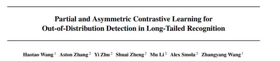
Icml2022 | partial and asymmetric comparative learning of out of distribution detection in long tail recognition
![[performance test] jmeter+grafana+influxdb deployment practice](/img/32/f07792734d040829398a90a2040146.png)
[performance test] jmeter+grafana+influxdb deployment practice
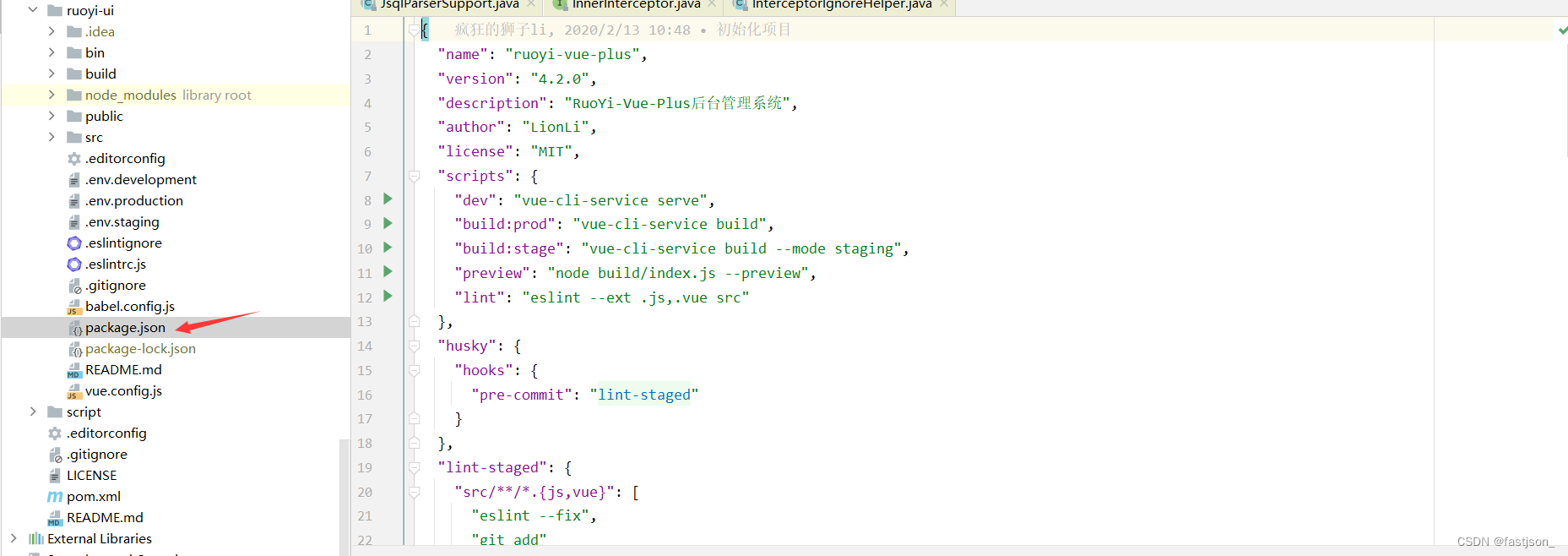
Idea configuring NPM startup

After the company went bankrupt, the blackstones came
Ant group open source trusted privacy computing framework "argot": open and universal
随机推荐
Precautions for RTD temperature measurement of max31865 module
Oracle date format conversion to_ date,to_ char,to_ Timestamp mutual conversion
Go deep into the underlying C source code and explain the core design principles of redis
RPC protocol details
在线协作产品哪家强?微软 Loop 、Notion、FlowUs
Go语言学习教程(十六)
基于FPGA的超声波测距
2022年阿里Android高级面试题分享,2022阿里手淘Android面试题目
The road of enterprise digital transformation starts from here
国内低代码开发平台靠谱的都有哪些?
Redhat7.4 configure Yum software warehouse (rhel7.4)
Analysis of postman core functions - parameterization and test report
Taishan Office Technology Lecture: from the layout height of the line, talk about the height overflow and height shrinkage of the drawing height (launched in the whole network)
决策树与随机森林
The basic grammatical structure of C language
华为让出的高端市场,小米12S靠徕卡能抢到吗?
【历史上的今天】7 月 5 日:Google 之母出生;同一天诞生的两位图灵奖先驱
Oracle 中文排序 Oracle 中文字段排序
ROS installation error sudo: rosdep: command not found
Overview of video self supervised learning