当前位置:网站首页>Common model making instructions
Common model making instructions
2022-07-05 22:43:00 【Ideal migrant workers】
Common model making instructions
Before starting today's study, insert a knowledge point , The geometry created in different views has different directions . If we create in the front view , It will be like this :
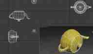
Create models in different views , The plane of the generated mesh will also be different . And we can use shortcut keys to switch different views in the perspective view to create geometry in different directions .
Modifier
Let's first see the first line of the command panel :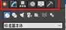
First, the first row of little suns , Yes create panel , You can create some geometry . The second row of quarter rings , Is the modification panel , Also called edit panel , Click this icon to see some parameters of the selected geometry problem :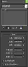
This is a cuboid , We can modify the length, width, height and segment in the parameter bar , For example, we will change the sub paragraphs to 2, Round the parameters to see the effect :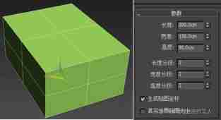
stay max in , We create new geometry with randomly assigned colors , We need to modify it by ourselves . You can change the name and color of the model above the parameter bar :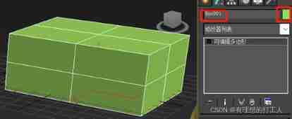
In this color bar, we can also turn off random color assignment :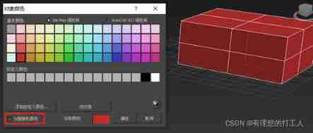
thus , The currently selected box and the geometry created later will be set to red .
Of course , We also need to deform this geometry , You need to select this geometry , Right click to convert to editable poly :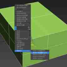
There will be some changes :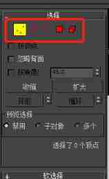
The content enclosed in the red box is hierarchy , From left to right, point by point 、 Press edge 、 By boundary 、 By polygon 、 Edit by element . First select click , Click the corresponding position , Then select the point you want to edit in the graph , Then press w For mobile :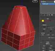
In this picture , We selected the top four points of the box to move . Of course, we can also rotate , Or choose another level , Try it yourself . One thing to note is , The box created in this way has no boundary , The boundary can be understood as a missing face , namely “ hole ”. Elements are mainly used for the separation of overlapping or contained two individuals .
The shortcut keys corresponding to these five levels are 1 To 5( Not a keypad ),6 Is the shortcut key of the object .
object
First of all, we need to understand what is an object , Object representation actually means model . When we select an object , There will be a line of prompt in the status box in the lower left corner :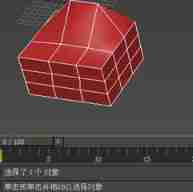
After selecting the level, we want to go back to selecting the object , You can press 6 recovery . When the shortcut key fails , We can find the keyboard shortcut override switch of the toolbar :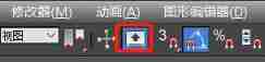
command
Only this and nothing more , We have learned to adjust points , Line , Noodles , But that's not enough , We need to learn to add points to the model on this basis , Add lines , Add noodles and other operations , This process requires commands .
First, in the function area ( Also called graphite tool ) Click the modeling in the upper left corner ( Must be editable poly ), You can see some commands that we need to understand :
It should be noted that , Select different levels of editable poly on the command line , The content displayed here will be different .
Many of the above commands can also be found elsewhere , First lengthen the command bar on the right , To facilitate observation :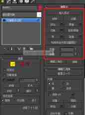
Or right click on the model :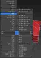
Now let's summarize the commonly used commands :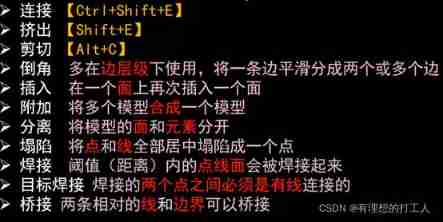
Connect
Connection is an operation between points , We select click in the hierarchy , Then press Ctrl Key plus select several points , Connect :
If you add more points in the process , You can hold down the alt Conduct subtraction ; You can also use Crtil+i Reverse selection .
It should be noted that , Connections cannot be crossed , such as :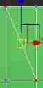
These two red dots have been connected , We can't choose two blue dots to connect .
Squeeze out
We choose the level we need , Then select the part you want to extrude , Then select extrude , You can achieve this effect :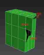
When you experience it, you should pay attention that the up and down movement of the mouse and the left and right movement will have different extrusion effects .
shear
The cutting command here is different from the familiar cutting , It's more like paper cutting in life . Remember the connection just mentioned that there is no way to cross the line ? Cutting can be forced to cross the line :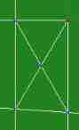
A new point arises at the intersection , We can also pull it out :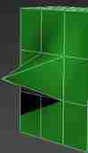
Of course , We can also cut it into broken lines , The intersection of the cut line and other lines will also produce new points , When you subtract a face , We can extrude this surface :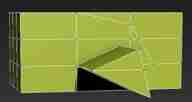
This is the conventional use of cutting .
Chamfering
Chamfer is also called chamfer , If we need a dumbbell , You need to use the chamfer operation . First create a cylinder , Change its height segment to 3, The end section is 1, Number of edges for 8. Select the level as edge , Double click a line segment to select a whole closed curve :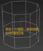
Then we click on the red line , Use the chamfer command , Slide the mouse up and down , This line will become two :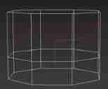
If we zoom a line , It's going to be like this :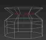
Then cut corners , Drag this red line to change the radian :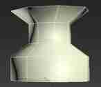
It can be seen that , Chamfer can be used to reduce radian , Make the model smoother .
But cut corners like this , If we need to add a lot of lines , It seems inefficient . To solve this problem, you can choose chamfer in the command bar on the right :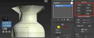
The first blue box can control the distance between the two red lines , In the second box, you can select the number of lines cut , Control the smoothness of the model . After adjustment, click √ You can save and close .
Insert
Insert can only be used on faces , So we have to choose the face level first . After selecting the level , Select the face to be inserted , Right click to select Insert , Then you can hold down the mouse and drag :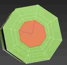
Inserting is actually inserting another face on the original face , After inserting, you can translate this face , Rotation and other operations :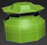
additional & Separate
Addition is to combine one or more models with another . We select an editable poly , Right click to select attach , Then select another editable model , These two models become one , The color will also be unified , When we choose one of them , Both models will be selected :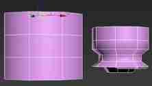
Attached model , You can select the element level to move alone .
At the element level , Select the separation of the command line , You can separate the two models :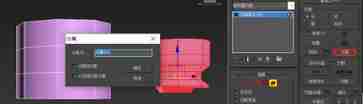
The color of the model just separated is still the same .
This is the separation between the two models , We can also use area separation , First select the face level , Then select the face to be separated , Click to separate . After separation, we can exit the hierarchy and drag the face of the banking office out of the model :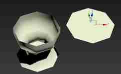
Of course , Face levels can also be added , However, we need to select all the faces that need to be attached .
Collapse
Collapse is to collapse a part of points and lines into a point . Select some points at the store level :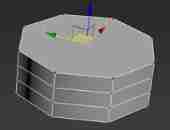
Then choose collapse :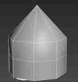
The selected point just now becomes a . Insert a knowledge point here , When we select the edge level , It can move the line .
Of course , Online level , Collapse operation can be carried out at face level .
Target weld
Collapse operation is uncontrollable , It will only collapse the selection into a central point . Target welding is somewhat similar to collapse , Two points can be welded together according to the path . First, select a point under the point level , Then right click to select the target welding , Pull to another point :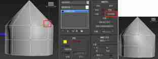
Target welding must have a route , If there is no connection between two points , The target welding cannot be carried out .
welding
Welding can merge points, lines and surfaces within a certain distance . Let's take the split face as an example . First, select the whole model according to the line level , Right click to select split ( You cannot use command line segmentation ), Then select the face level , Separate one of the faces from the body :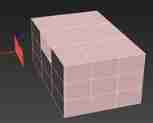
Then, under the point level, frame all points of the model and all points of the face to be welded , Then right-click , Click the small box in front of welding two words , Then select the appropriate welding threshold :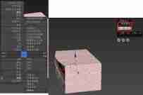
Just connect them again . Because the two parts are far apart , Therefore, certain deformation also appeared after welding .
The bridge
Bridging can connect two lines . For example, we delete a part of aid :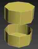
In the hollowed out part, we bridge the upper and lower lines at the online level :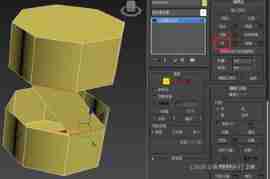
Bridging is a less common command , Understanding can .
texture of material
Material is what we need to add to the model , Press m Key to open the material editor :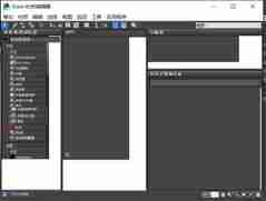
The initial interface is like this . Click mode , Select compact material editor :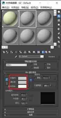
You will probably see such an interface . The six ball materials here are the same , The color can be adjusted in the red box . After adjustment , You can press and hold this ball , Drag onto the model to which you want to add material , Then release the left button :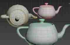
Of course , You can also adjust the material , Select the model to which you want to add materials , Then click to put the material to the specified object scene :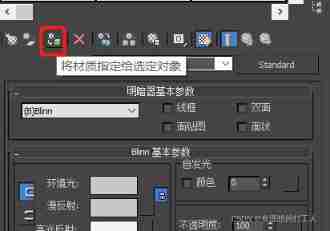
And a little egg : Because before adding materials , The color of lines and faces is the same , But adding materials will only change the color display of the face , Therefore, there is a gray red line , The situation of grey surface and green line .
You can also do this for shaders : Store a picture on the desktop , Then pull it onto a shader :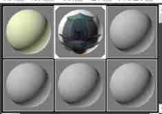
Now create a plane and add materials to it :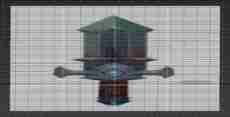
If there are all swords on the plane , You can open the modifier , choice uvw an :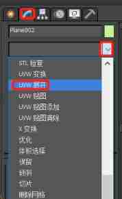
Then open the uvw Editor , Select Map 1 in the upper right corner :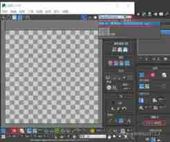
Then click on the Red Square and white cube in the lower left corner , Then a grid will appear in the screen , Adjust the mesh to a plane with only one sword .
In order to display more stickers and pictures , Let's check the resolution of the picture :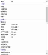
Put this 239( wide )*667( high ) Fill in the newly created plane attribute , And change the segment of the plane to 1: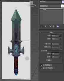
Then we put this picture under (0,0,0) spot . Press w key , Then box this picture , stay max Find x,y and z, And set them to zero :
If we need to make the picture stand up , Can press e And frame the picture , Then adjust x The parameters for 90( Readers can set it by themselves ). If the grid gets in the way , Can press g close .
Next we put the sword along y Move a distance axially , Then select the object , Right click the point object properties :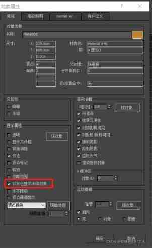
Click this to display the frozen object in gray , Click ok , Then right click the sword , Choose to freeze the current object , Frozen patches . In order to avoid trouble caused by wrong selection when we operate later .
Okay , That's all for today . We mainly introduced max Complete some basic commands and specific operations of a model . Later, an article will be published to make a model of this sword , I will also use a lot of the instructions introduced today . After reading, please be familiar with these instructions .
边栏推荐
- Hcip day 16
- 2022 Software Test Engineer salary increase strategy, how to reach 30K in three years
- Metaverse ape received $3.5 million in seed round financing from negentropy capital
- TCC of distributed solutions
- Business introduction of Zhengda international futures company
- What changes has Web3 brought to the Internet?
- Win11 runs CMD to prompt the solution of "the requested operation needs to be promoted"
- Paddle Serving v0.9.0 重磅发布多机多卡分布式推理框架
- Analysis of the problem that the cookie value in PHP contains a plus sign (+) and becomes a space
- Solutions for unexplained downtime of MySQL services
猜你喜欢

关于MySQL的30条优化技巧,超实用
Nacos 的安装与服务的注册
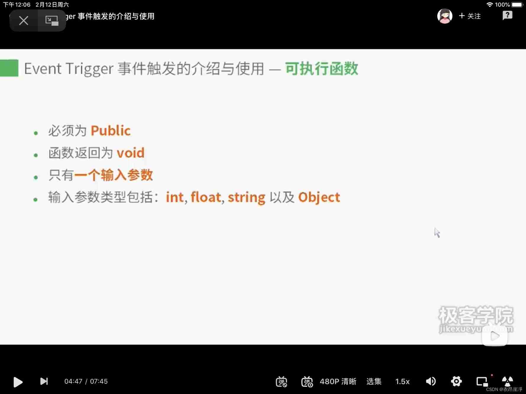
Event trigger requirements of the function called by the event trigger
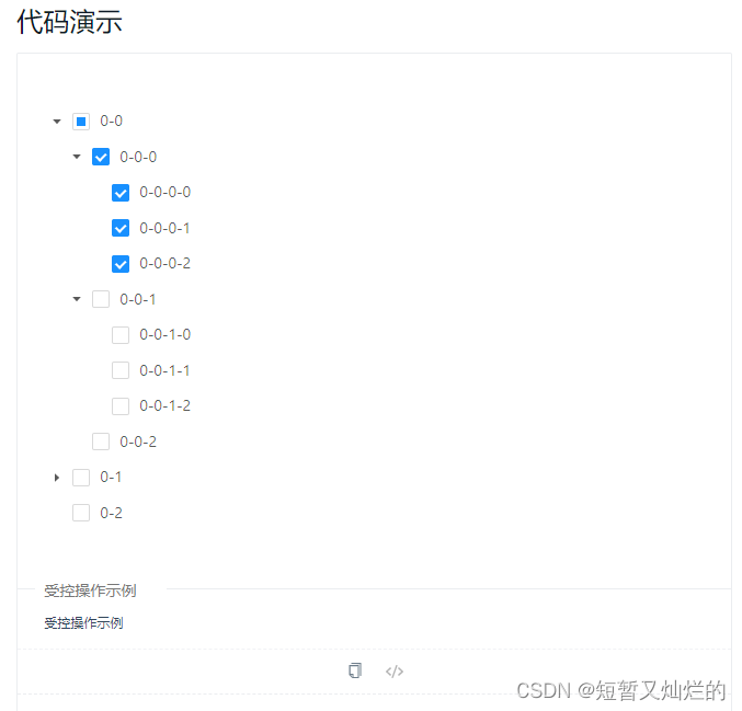
All expansion and collapse of a-tree
![[error record] groovy function parameter dynamic type error (guess: groovy.lang.missingmethodexception: no signature of method)](/img/3e/34b45cd14f0302bb381efd244bc68f.jpg)
[error record] groovy function parameter dynamic type error (guess: groovy.lang.missingmethodexception: no signature of method)
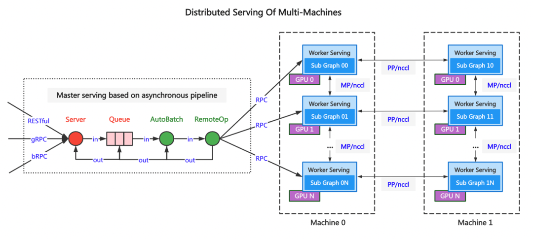
Paddle Serving v0.9.0 重磅发布多机多卡分布式推理框架

Calculation method of boundary IOU

Metaverse ape received $3.5 million in seed round financing from negentropy capital
Nacos installation and service registration
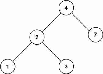
700. Search in a Binary Search Tree. Sol
随机推荐
2022-07-05: given an array, you want to query the maximum value in any range at any time. If it is only established according to the initial array and has not been modified in the future, the RMQ meth
Qtquick3d real time reflection
Analysis of the problem that the cookie value in PHP contains a plus sign (+) and becomes a space
解决thinkphp启动时“No input file specified”的问题
Postman核心功能解析-参数化和测试报告
我把开源项目alinesno-cloud-service关闭了
70. Climbing Stairs. Sol
Opencv judgment points are inside and outside the polygon
Search: Future Vision (moving sword)
Binary tree (II) -- code implementation of heap
BFC block level formatting context
The introduction to go language is very simple: String
Binary tree (III) -- heap sort optimization, top k problem
The new content of the text component can be added through the tag_ Config set foreground and background colors
Hcip day 16
Character conversion PTA
Starting from 1.5, build a micro Service Framework -- log tracking traceid
Nacos 的安装与服务的注册
Tiktok__ ac_ signature
Solutions for unexplained downtime of MySQL services