当前位置:网站首页>Stm32-dac Experiment & high frequency DAC output test
Stm32-dac Experiment & high frequency DAC output test
2022-07-02 14:28:00 【Early to bed and early to rise Chery】
1.DAC Basics
majority STM32 The chip will come with it DAC output module (12 Digital input , Voltage output type DAC)
For example, commonly used STM32F103RCT6 ( RAM48K FLASH 256K), Chip DAC There are two output channels
This experiment uses a single DAC passageway 1, use 12 Bit right aligned format output .
STM32F103 Reference manual P185:
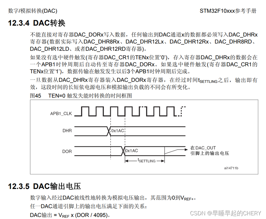
DAC The process , Briefly summarized as : to DAC_DORx Register assignment , then DAC Module processing , after t_setting after , Analog output pin changes . from STM32F103RCT6 The data book of t_setting The biggest problem is 4us. therefore DAC The fastest conversion speed is : 1/4μs=250KHz about . meanwhile , This frequency is also far less than the main frequency of the chip 72MHz, Meet the square wave duty cycle modulation -DAC Output requirements .
2. Enable DAC The general steps of
Turn on PORTA The clock . STM32F103RCT6 Of DAC passageway 1 stay PA4 . So open the pin first A Series clock , The pin mode is set to analog input ( Because it enables DAC After the passage , Corresponding GPIO The pin will automatically contact DAC Connected to the analog output of , Set as input to avoid additional interference - Then you can test whether it is feasible to set the output mode )
Code:
RCC_APB2PeriphClockCmd(RCC_APB2Periph_GPIOA, ENABLE ); // Can make  PORTA The clock
GPIO_InitStructure.GPIO_Mode = GPIO_Mode_AIN; // Pin configuration   Analog input
step2: Can make DAC1 The clock of . Check the data book , find DAC Module clock , Call the function in the firmware library to start :
RCC_APB1PeriphClockCmd(RCC_APB1Periph_DAC, ENABLE ); // Can make DAC Channel clock step3: Initialize the working mode :
This time use single channel enable , passageway 1 Output cache off , Trigger response off , Waveform generator ( Triangle 、 square wave ) close . Just the most basic DAC Output , The function called is dac In the firmware library :
void DAC_Init(uint32_t DAC_Channel, DAC_InitTypeDef* DAC_InitStruct)
The parameters of the function are in the structure DAC_InitType In the definition of :
typedef struct

{

  uint32_t DAC_Trigger;    // The value here is  DAC_Trigger_None.

  uint32_t DAC_WaveGeneration;     // Whether to use waveform generation   None

  uint32_t DAC_LFSRUnmask_TriangleAmplitude;  // shielding / Amplitude selector , It only takes effect when the waveform occurs

  uint32_t DAC_OutputBuffer;          // Disable  DAC1  Output cache off

}DAC_InitTypeDef;
/* Whether trigger function is enabled : Sometimes you need to press the key to adjust the output voltage . One way is to use external interrupts EXTI9, Another way is to use software trigger . If you will DAC_InitTypeDef.DAC_Trigger Set to DAC_Trigger_None, that , No other trigger source is required , Use it directly DAC_SetChannelxData(), The output voltage can be set . If a software trigger is used , that , Every time I use DAC_SetChannelxData() After modifying the output voltage , You also need to call DAC_SoftwareTriggerCmd(), The purpose is to enable the software to trigger */
step4: passageway 1 Output enable
DAC_Cmd(DAC_Channel_1, ENABLE); // Can make DAC1step5: Set up DAC value :
void DAC_SetChannel1Data(uint32_t DAC_Align, uint16_t Data)
It is also a function in firmware , Source code :
/**
  * @brief  Set the specified data holding register value for DAC channel1.
  * @param  DAC_Align: Specifies the data alignment for DAC channel1.
  *   This parameter can be one of the following values:
  *     @arg DAC_Align_8b_R: 8bit right data alignment selected
  *     @arg DAC_Align_12b_L: 12bit left data alignment selected
  *     @arg DAC_Align_12b_R: 12bit right data alignment selected
  * @param  Data : Data to be loaded in the selected data holding register.
  * @retval None
  */
void DAC_SetChannel1Data(uint32_t DAC_Align, uint16_t Data)
{
  __IO uint32_t tmp = 0;

  /* Check the parameters */
  assert_param(IS_DAC_ALIGN(DAC_Align));
  assert_param(IS_DAC_DATA(Data));

  tmp = (uint32_t)DAC_BASE;
  tmp += DHR12R1_OFFSET + DAC_Align;

  /* Set the DAC channel1 selected data holding register */
  *(__IO uint32_t *) tmp = Data;
}
First, the first parameter is 12 position D Input or 8 position D(Right or Left) Input
The second parameter is the output value . Note the second parameter value 12 Bit is in 0~4095(2^12-1) 8 Bit in 0~255
Besides , You can also read the channel output value in the software :DAC_GetDataOutputValue(DAC_Channel_1);
3.DAC initial
#include "dac.h"

//
// This procedure originates from :
// The punctual atoms @ALIENTEK
//Copyright(C)  Guangzhou Xingyi Electronic Technology Co., Ltd  2009-2019
//
//DAC passageway 1 Output initialization
void Dac1_Init(void)
{

	GPIO_InitTypeDef GPIO_InitStructure;
	DAC_InitTypeDef DAC_InitType;

	RCC_APB2PeriphClockCmd(RCC_APB2Periph_GPIOA, ENABLE );	  // Can make PORTA Channel clock
  RCC_APB1PeriphClockCmd(RCC_APB1Periph_DAC, ENABLE );	  // Can make DAC Channel clock

	GPIO_InitStructure.GPIO_Pin = GPIO_Pin_4;				 //  port configuration
 	GPIO_InitStructure.GPIO_Mode = GPIO_Mode_AIN; 		 // Analog input
 	GPIO_InitStructure.GPIO_Speed = GPIO_Speed_50MHz;
 	GPIO_Init(GPIOA, &GPIO_InitStructure);
	GPIO_SetBits(GPIOA,GPIO_Pin_4)	;//PA.4  High output

	DAC_InitType.DAC_Trigger=DAC_Trigger_None;	// Don't use the trigger function  TEN1=0
	DAC_InitType.DAC_WaveGeneration=DAC_WaveGeneration_None;// No waveform generation
	DAC_InitType.DAC_LFSRUnmask_TriangleAmplitude=DAC_LFSRUnmask_Bit0;// shielding 、 Amplitude setting
	DAC_InitType.DAC_OutputBuffer=DAC_OutputBuffer_Disable ;	//DAC1 Output cache off  BOFF1=1
  DAC_Init(DAC_Channel_1,&DAC_InitType);	 // initialization DAC passageway 1

	DAC_Cmd(DAC_Channel_1, ENABLE);  // Can make DAC1

  DAC_SetChannel1Data(DAC_Align_12b_R, 0);  //12 Bit right alignment data format setting DAC value

}

// Set up channels 1 Output voltage
//vol:0~3300, representative 0~3.3V
void Dac1_Set_Vol(u16 vol)
{
	float temp=vol;
	temp/=1000;
	temp=temp*4096/3.3;
	DAC_SetChannel1Data(DAC_Align_12b_R,temp);//12 Bit right alignment data format setting DAC value
}
initial Function is to encapsulate the above steps .
void Dac1_Set_Vol(u16 vol) Function support float Voltage conversion , Otherwise, every time you call DAC_SetChannel1Data() Time has to be converted .
4.DAC High frequency experiment
Measure in the main function DAC The highest frequency of , And then in LCD On reality . First, use one up-down loop , Give Way DAC The output keeps changing , Then change every time Fre++ . Clear the timer once per second Fre, And then record the highest Fre, That is to say DAC Highest frequency .
#include "led.h"
#include "delay.h"
#include "sys.h"
#include "usart.h"
#include "lcd.h"
#include "adc.h"
#include "dac.h"
#include "timer.h"
u32 Fre=0; //extern Variables are defined as global variables
u16 adcx;
float temp;
u8 dvup=1;
u32 HighestFre=0;
u16 dacval=0;
int main(void)
{
NVIC_PriorityGroupConfig(NVIC_PriorityGroup_2);// Set interrupt priority group 2
delay_init(); // Delay function initialization
uart_init(9600); // The serial port is initialized to 9600
LED_Init(); // Initialization and LED Connected hardware interface
LCD_Init(); // initialization LCD
Adc_Init(); //ADC initialization
Dac1_Init(); //DAC passageway 1 initialization
TIM3_Int_Init(9999,7199);//10Khz The counting frequency of , Count to 10000 by 1000ms
POINT_COLOR=RED;// Set the font to red
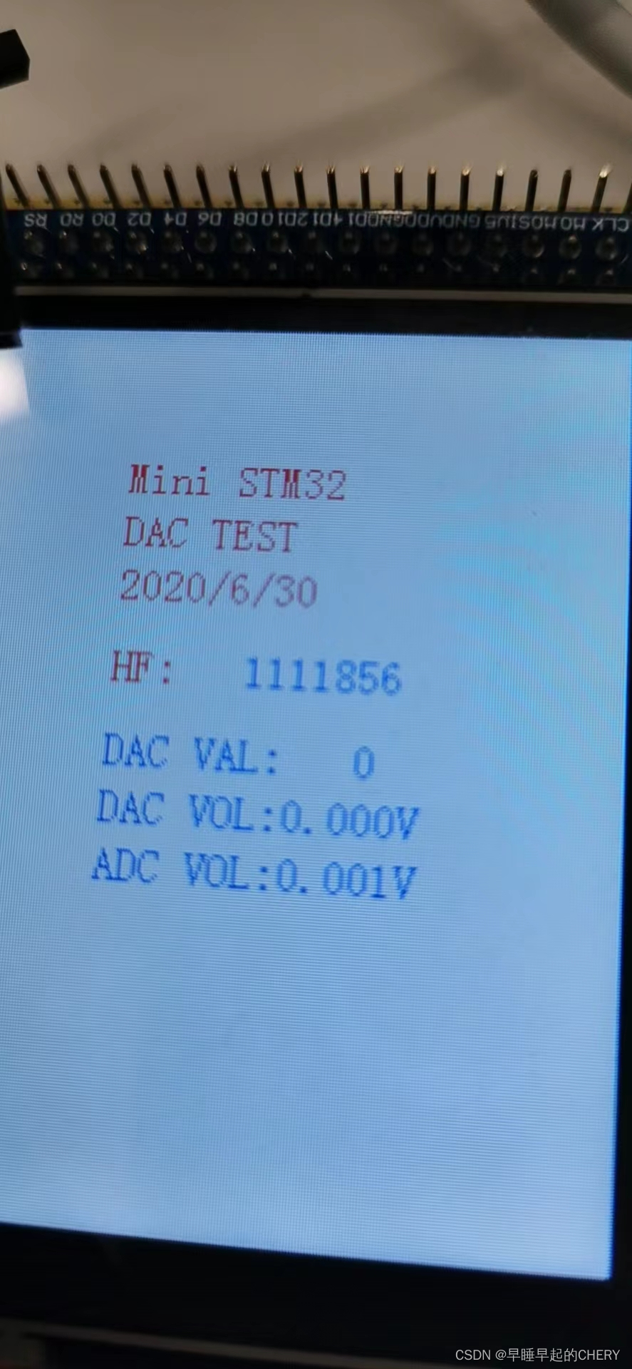
LCD_ShowString(60,50,200,16,16,"Mini STM32");
LCD_ShowString(60,70,200,16,16,"DAC TEST");
LCD_ShowString(60,90,200,16,16,"2020/6/30");
LCD_ShowString(60,120,200,16,16,"HF:");
// Display prompt message
POINT_COLOR=BLUE;// Set the font to blue
LCD_ShowString(60,150,200,16,16,"DAC VAL:");
LCD_ShowString(60,170,200,16,16,"DAC VOL:0.000V");
LCD_ShowString(60,190,200,16,16,"ADC VOL:0.000V");
DAC_SetChannel1Data(DAC_Align_12b_R, 0);// Set up DAC1 passageway 12 position R For its , Output 0
while(1)
{
if(dvup){
if(dacval<4000) dacval+=20;
else dvup=0;
}
else{
if(dacval>200) dacval-=20;
else dvup=1;
}
DAC_SetChannel1Data(DAC_Align_12b_R, dacval);//DAC Output
Fre++;
}
}
Set refresh in timer interrupt LCD,main Update the program as soon as possible DAC frequency .
Timer timer.c Medium IRQHandler:
extern u32 Fre;
extern u16 adcx;
extern float temp;
extern u8 dvup;
extern u32 HighestFre;
extern u16 dacval;
u32 tempu32;


void TIM3_IRQHandler(void)   //TIM3 interrupt
{
	if (TIM_GetITStatus(TIM3, TIM_IT_Update) != RESET) // Check the specified TIM Whether the interruption occurs or not :TIM  Interrupt source
		{
		TIM_ClearITPendingBit(TIM3, TIM_IT_Update  );  // eliminate TIMx Interrupt pending bit of :TIM  Interrupt source

		if(Fre>HighestFre) HighestFre=Fre;
		tempu32=HighestFre;
		LCD_ShowxNum(100,120,tempu32,8,16,0); // Show highest frequency


		adcx=DAC_GetDataOutputValue(DAC_Channel_1);//DAC
		LCD_ShowxNum(124,150,adcx,4,16,0);     	// Show DAC Register values
		temp=(float)adcx*(3.3/4096);			// obtain DAC Voltage value
		adcx=temp;
		LCD_ShowxNum(124,170,temp,1,16,0);     	// Display the integral part of the voltage value
		temp-=adcx;
		temp*=1000;
		LCD_ShowxNum(140,170,temp,3,16,0X80); 	// Display the decimal part of the voltage value
		adcx=Get_Adc_Average(ADC_Channel_1,10);		// obtain ADC Conversion value
		temp=(float)adcx*(3.3/4096);			// obtain ADC Voltage value
		adcx=temp;
		LCD_ShowxNum(124,190,temp,1,16,0);     	// Display the integral part of the voltage value
		temp-=adcx;
		temp*=1000;
		LCD_ShowxNum(140,190,temp,3,16,0X80); 	// Display the decimal part of the voltage value

		LED0=!LED0;

		Fre=0;
		}
}
4. experimental result

CPU It's basically going on DAC operation . And estimated 250kHz In an order of magnitude , But it will be higher , Maybe the timer is not accurate enough , as well as Tsetting It will be shorter than the mark .
When the main program circulates , The main time consuming is DAC link :
while(1)
{
if(dvup){
if(dacval<4000) dacval+=20;
else dvup=0;
}
else{
if(dacval>200) dacval-=20;
else dvup=1;
}
DAC_SetChannel1Data(DAC_Align_12b_R, dacval);//DAC Output
Fre++;
}
Try to modify the source code :
/**
  * @brief  Set the specified data holding register value for DAC channel1.
  * @param  DAC_Align: Specifies the data alignment for DAC channel1.
  *   This parameter can be one of the following values:
  *     @arg DAC_Align_8b_R: 8bit right data alignment selected
  *     @arg DAC_Align_12b_L: 12bit left data alignment selected
  *     @arg DAC_Align_12b_R: 12bit right data alignment selected
  * @param  Data : Data to be loaded in the selected data holding register.
  * @retval None
  */
void DAC_SetChannel1Data(uint32_t DAC_Align, uint16_t Data)
{
  __IO uint32_t tmp = 0;

  /* Check the parameters */
  //assert_param(IS_DAC_ALIGN(DAC_Align));
  //assert_param(IS_DAC_DATA(Data));

  tmp = (uint32_t)DAC_BASE;
  tmp += DHR12R1_OFFSET + DAC_Align;

  /* Set the DAC channel1 selected data holding register */
  *(__IO uint32_t *) tmp = Data;
}
When modifying, put two lines assert_param The comments , Skipped the parameter check . The highest frequency has hardly increased . explain CPU Computation is not a major time-consuming project .
Put... In the main program DAC_SetChannel1Data The comments , Measured without DAC The highest frequency of other parts of the link :
1111kHz, It shows that other calculation steps in the cycle take about 0.9us.
Join in DAC It takes about 1/630kHz=1.6us.
So do it once DAC It takes about 0.7us. This value is higher than that given in the reference manual Tsetting Many small , But here's the thing DAC_SetChannel1Data There seems to be no ACK link , That is, no detection DAC Has it been completed . So further DAC High frequency limit test can be used DAC Square wave output + Test with oscilloscope .
边栏推荐
- freemarker的使用
- In 2021, the global revenue of structural bolts was about $796.4 million, and it is expected to reach $1097.6 million in 2028
- 给Android程序员的一些面试建议「建议收藏」
- Fabric. JS dynamically set font size
- Use of swagger
- 数据湖(十一):Iceberg表数据组织与查询
- 删除元素(带过渡动画)
- Solve the problem that openocd fails to burn STM32 and cannot connect through SWD
- Design of non main lamp: how to make intelligent lighting more "intelligent"?
- Systemserver process
猜你喜欢
万物生长大会在杭召开,当贝入选2022中国未来独角兽TOP100榜单

没有从远程服务器‘‘映射到本地用户‘(null)/sa‘的远程用户‘sa‘及服务主密码解密错误的解决办法

Yyds dry goods inventory software encryption lock function

Design of non main lamp: how to make intelligent lighting more "intelligent"?

Chinese science and technology from the Winter Olympics (III): the awakening and evolution of digital people
In 2021, the global styrene butadiene styrene (SBS) revenue was about $3722.7 million, and it is expected to reach $5679.6 million in 2028

Borui data integrated intelligent observable platform was selected into the "Yunyuan production catalogue" of China Academy of communications in 2022

Penetrate the remote connection database through the Intranet
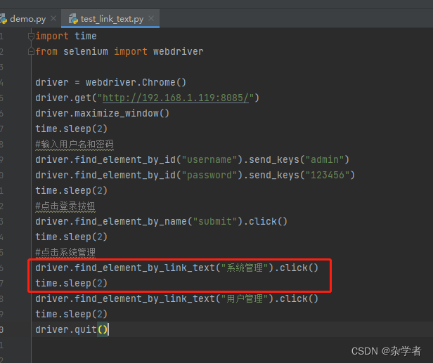
selenium 元素定位方法
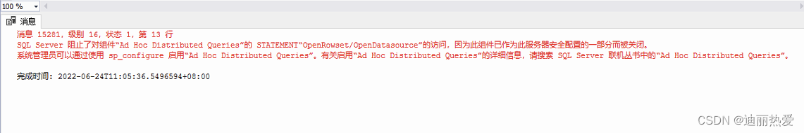
提示:SQL Server 阻止了对组件‘Ad Hoc Distributed Queries ‘的STATEMENT ‘OpenRowset/OpenDatasource“”
随机推荐
数据湖(十一):Iceberg表数据组织与查询
Tencent cloud tstor unified storage passed the evaluation of the first batch of basic file storage capabilities of the ICT Institute
< schematic diagram of oral arithmetic exercise machine program development> oral arithmetic exercise machine / oral arithmetic treasure / children's math treasure / children's calculator LCD LCD driv
docker mysql
MySQL45讲——学习极客时间MySQL实战45讲笔记—— 04 | 深入浅出索引(上)
mongodb的认识
Pycharm连接远程服务器
快解析:轻松实现共享上网
Codeforces Round #803 (Div. 2)(A~D)
Fabric.js 元素被选中时保持原有层级
Analysis of CPU surge in production environment service
Packet capturing tool Fiddler learning
途家木鸟美团夏日折扣对垒,门槛低就一定香吗?
Fabric.js 橡皮擦的用法(包含恢复功能)
Systemserver process
自定义事件,全局事件总线,消息订阅与发布,$nextTick
Whole house Wi Fi: a pain point that no one can solve?
Fabric.js 缩放画布
Use of freemaker
YOLOv3&YOLOv5输出结果说明